In This Edition
Quotations to Open On
Read More…
Feature Article
The Role of V&V in the Early Stages of the Lifecycle by Steven H. Dam
Read More…
Articles
What do the Terms Verification and Validation Really Mean? by Lou Wheatcraft
Systems Engineering Applied to Urban Transportation by J. Edward Anderson
Read More
- How Can We Share Solutions to Complex Systems Problems Across Domains and Application Areas?
- Emergence – The Interaction of the Parts of a System
- The Authentic Systems Engineer is More Effective
- INCOSE Netherlands’ Report on its “SE Experience” Event
- China’s Amazing Engineering Marvels
- System Integration Case Study Wanted
- 2017 System Dynamics Summer School at MIT – Application for Scholarship Support
Read More…
Featured Organizations
- Society of Engineering Science
Read More…
Conferences and Meetings
Read More…
Some Systems Engineering-Relevant Websites
Read More…
Systems Engineering Publications
- Design in Tech Report, by John Maedea
- From Modularity to Emergence: A Primer on the Design and Science of Complex Systems, by Chih-Chun Chen and Nathan Crilly
- A Primer on User Experience Design, by Joseph Dickerson
- Societal Trends in Technology, by Bruce Sterling
- 16 Rules of Engineering Design, by J. Edward Anderson
- Systems Engineering with SysML/UML: Modeling, Analysis, Design, by Tim Weikiens
Read More…
Systems Engineering Tools News
- Basics of The Systems Modelling Language (SysML)
- MagicDraw
Read More…
Education and Academia
- Changes to be Brought in Engineering Syllabi to Meet Industry Requirements
- The Optimum Place and Time to Introduce Systems Thinking is at Middle-School Level
- Future Engineering Careers will Depend on Present Education in Cyber-Physical Systems and IoT Integration
- The Mastership Program for Engineers in Training
- Systems Architecting and Engineering at the University of Southern California (USC)
Read More…
Standards and Guides
- Systems Engineering Standards: A Summary
Read More…
Definition to Close On
- Systems Engineering
Read More…
PPI and CTI News
Read More…
PPI Upcoming Participation in Professional Conferences
PPI and CTI Events
Quotations to Open On
The following quotations are attributed to Lou Wheatcraft, author of an article in this issue of SyEN:
“Requirements are the common thread that ties all system development lifecycle activities and work products together.”
“Writing requirements is an exercise in engineering, not an exercise in writing.”
“Requirements should not, and must not, be viewed in isolation, but rather viewed as how they relate to the whole.”
“We are 17 years into the 21st century, yet many are still trapped in 20th century thinking when it comes to requirements and systems engineering.”
“Technology is evolving at a rapid rate, especially information technology, not only resulting in more complex systems, but also enabling the documentation, management, and integration of large datasets that represent the many work products and underlying data and information generated as part of the SE lifecycle process activities.”
The Role of V&V in the Early Stages of the Lifecycle
by Steven H. Dam, Ph.D., ESEP
Abstract
System Verification and Validation (V&V) occur in the later parts of the system lifecycle to ensure that the requirements developed in the early phases of the lifecycle have been met. This paper discusses how to use the techniques of V&V, including simulation, early in the lifecycle to enhance the probability of success of the program by identifying errors early in the development and preparing for the V&V activities later in the lifecycle.
Email: steven.dam@specinnovations.com
Introduction
Having just watched the movie “Deepwater Horizon” (Achenbach, 2016) I observed the results when proper testing is skipped. If you have not seen the movie, several routine and critical tests were skipped and another test was performed with mixed results. The mixed results test had the result of people picking the optimistic conclusion, which turned out catastrophic.
We have seen these problems in many other instances. Just look at NASA Mishap Reports (Larson, 2009). They contain example after example of failures all through the lifecycle, often due to skipped tests. Such defects can be identified earlier in the lifecycle if modern modeling and simulation techniques are used. Unfortunately, most systems engineering and architecture work is done using the equivalent of Microsoft Office, which is fantastic for word processing, spreadsheets, and drawing tools, but wholly insufficient for engineering modeling and simulation.
The Lifecycle Model
If you are a systems engineer, you are likely familiar with the “V” lifecycle model. (Rook, 1986) Our version of the V is shown in Figure 1 below. This diagram shows the phases of the lifecycle as we decompose the system to a level from concept to where we can specify and build the components of the system. Then it shows the integration of the components to build up the system, while verifying and validating that the system meets the requirements.
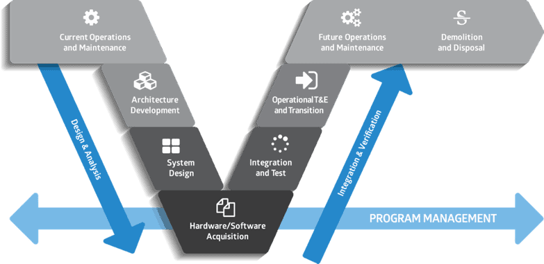
Figure 1. The “V” Lifecycle Model
The “V” shape reminds us of the parallel V&V activities that are affected as we decompose the system. For example, during the architecture development, it is important to derive the acceptance criteria as the basis for the operational test and evaluation (OT&E) and transition activities. A draft test and evaluation master plan (TEMP) can and should be produced during this architecture development phase. Unfortunately, this process often is not done at all or it is done in a way that renders it effectively useless.
In addition to this lack of test planning, often the architecture development takes the form of creating a series of drawings based on a limited language, such as Systems Modeling Language (SysML). The nine SysML drawings are necessary, but not sufficient, to capture all the information about the system, which includes the risks, decisions, costs, and other parameters needed to fully describe the system. The work also usually focuses on operations and ignores maintenance and various potential failure modes of the system. In addition to these problems, the drawings are usually just treated as static depictions of processes and components. Those drawings can contain significant errors in logic that do not become obvious until the equivalent phase coming up the “V.” As is well known, finding errors later in the lifecycle is very expensive and may even lead to program cancellation. (Albrecht, 2017).
Deriving Requirements from Scenarios
Often in the architecture development phase, requirements, particularly functional requirements, have not been developed to a sufficient level that we can derive the verification requirements needed to begin test planning. In view of this fact, scenario analysis is often used to develop models of the operations (and maintenance) of the system, from which the functional requirements for the system can be identified. The challenge in using scenario analysis is evolving a set of scenarios that will ensure that the breadth and depth of the functionality will be developed. A number of years ago, I developed an approach that applied the idea of a test matrix to the development of scenarios for architecture analysis. The basic strategy was to develop a list of scenarios and a set of characteristics of these scenarios (Dam, 2007). These two pieces of information would then form a matrix, similar to a test matrix where you have the test scenarios juxtaposed with the parameters you want to measure. An example is shown in Figure 2. The example shown is a fairly simplistic example, but this can be expanded and used for much larger problems.
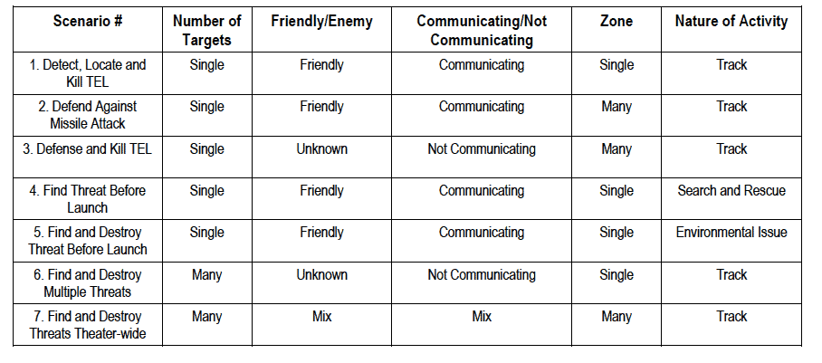
Figure 2. An Example of a Scenario Matrix
Once we have identified these scenarios, then we can build models of each. Figure 3 shows an Action Diagram of the first scenario for the table above (Dam, 2014).
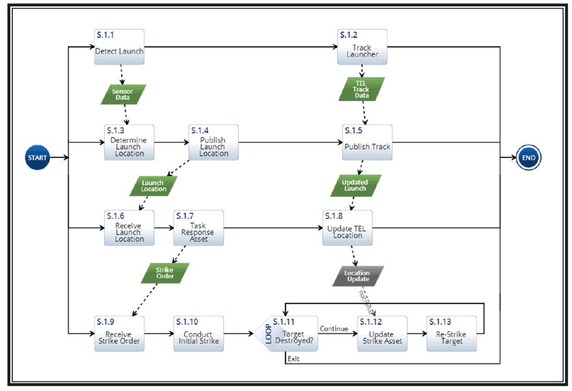
Figure 3. Example of Scenario 1 Action Diagram Model
These models can then be used to derive the functional requirements for the system. Several tools automate this process by reading the functional elements of the models and their relationships to physical entities, such as the system, and then produce requirements and/or documents that can be used as the basis for the system specification.
But, how do we know this model works? Could we be building errors in the logic in these diagrams? The answer to these questions comes from further analysis using simulation techniques.
Application of Simulation
We are very familiar with simulation as one of the methods for V&V, along with analysis, inspection, demonstration, and test. We can apply simulation in the early phases of the lifecycle by applying various simulation techniques to the models developed in the previous section. Discrete Event Simulation (DES) uses “a mathematical/logical model of a physical system that portrays state changes at precise points in simulated time” [Albrecht]. Unfortunately, many of the modeling tools do not have an embedded DES capability, so models developed using the drawing technique of choice often have to be redeveloped in the simulation tool. The question becomes “Is this the same model?” In general, the answer is probably no. Just as when we had a diagram to a programmer and receive code back, the simulation modeler will make changes that often are not documented to fix problems with the original model. Fortunately, several tools [Tools] have both the modeling capability and a full DES. An example of the execution of the model is shown below in Figure 4.
Recently, I have discovered that given the uncertainty in the timing of each step of the process, the probabilities of failure paths, the variability of resources, and many other factors, DES is insufficient to estimate the potential range of capabilities of the systems being modelled. However, if we apply another simulation technique in conjunction with DES, we can easily include these uncertainties in the modeling. This technique is called Monte Carlo simulation. Monte Carlo simulation, the name given by John van Neumann and Stanislaw M. Ulam to reflect its gambling similarity, utilizes models of uncertainty where representation of time is unnecessary. The term originally attributed to a situation in which a difficult non-probabilistic problem is solved through the invention of a stochastic process that satisfies the relations of the deterministic problem. A more recent characterization is that Monte Carlo is the method of repetitive trials. This latter definition fits our interest in that what we want to do is to repeat the simulation produced by the DES, but vary the points within each distribution to see the impacts of the uncertainties in the timing, resources, branching, and other probabilistic elements of the simulation. Figure 5 shows an example of the Monte Carlo results of executing the same scenario shown in Figure 3.
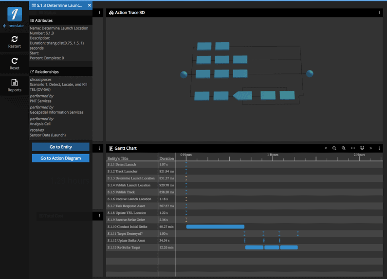
Figure 4. Example of Discrete Event Simulation Output from Scenario 1
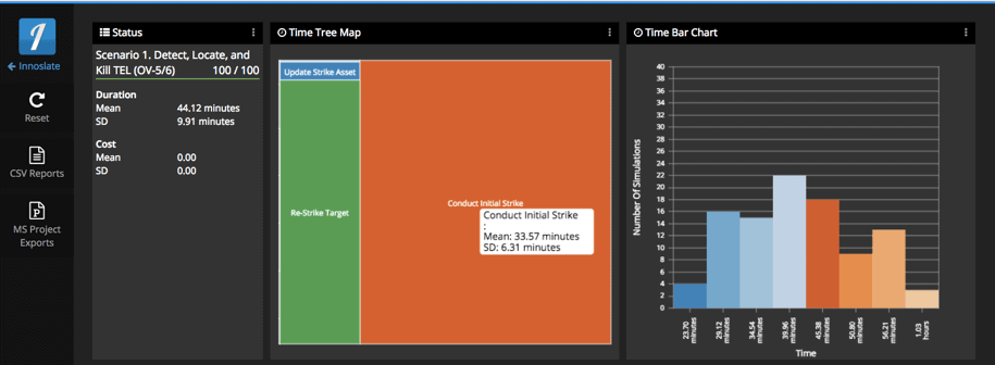
Figure 5. Example of Monte Carlo Simulation Output from Scenario 1
Figure 5 is a Time Tree Map, which provides the mean and standard deviation of each step of the process. The Time Bar Chart shows the distribution in time of the number of runs that occur within the specified time bins. This example was only executed in the model 100 times. To get a more accurate estimate (higher confidence interval), you can run the simulation many more times (Driels, 2004).
Test Planning
Another V&V activity that can at least begin early in the lifecycle is the test planning. As you can imagine, many final operational tests must be conducted at specialized ranges that provide the necessary test equipment and telemetry capabilities needed for final test. These ranges often must be scheduled years in advance. In addition, you may have to develop specialized test equipment and/or arrange for experts/users to participate in this kind of testing. Such tests are also expensive and must maximize the value. These reasons alone drive the need for early test planning.
Figure 6 shows an example of how to capture test expectations and results in a modeling tool.
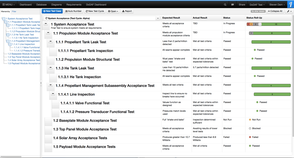
Figure 6. Example of Capturing Test Plans and Results in a Modeling Tool
Future V&V
Having the requirements, combined with the models and V&V test plans, enables the potential for automating the V&V process. We can run a simulation against the test case using well defined performance parameters, including time, resource usage, and cost. Using the Monte Carlo simulation provides a confidence interval that can be improved over time as better data become available through the lifecycle process. This capability can then track the progress in improvement of the performance parameters from the initial estimation into final test results. The software industry has had the capability to conduct automated testing for some time due to their use of integrated development environments (IDEs). What is needed is an IDE for systems engineering. The capabilities discussed above come very close to this desired future state.
Summary
Using V&V techniques and effective planning for V&V early in the lifecycle provide many benefits to any project. Although it costs a little more up front, by discovering errors early we save problems later in the lifecycle and even save lives once the system is deployed. Applying these techniques and planning requires understanding the needs of the V&V personnel and thus should encourage the involvement of people with these skills early and throughout the lifecycle.
References
Achenbach, J. “’Deepwater Horizon’ movie gets the facts mostly right, but simplifies the blame.” The Washington Post. September 29, 2016. Accessed August 2, 2017. https://www.washingtonpost.com/news/achenblog/wp/2016/09/29/deepwater-horizon-movie-gets-the-facts-mostly-right-but-simplifies-the-blame/?utm_term=.34ca084b11e5.
Larson, W. J. et al. (2009). Applied Space Systems Engineering. editors, McGraw-Hill Education.
Forsberg, K. and Mooz, H. (1991). The Relationship of Systems Engineering to the Project Cycle. First Annual Symposium of the National Council on Systems Engineering (NCOSE).
Albrecht, M. C. (2010). Introduction to Discrete Event Simulation. Retrieved from http://www.albrechts.com/mike/DES/Introduction%20to%20DES.pdf.
Dam, S. H. (2007). Intelligent Operational Scenarios – a Strategy for Cost-Saving Scenario Selection. 17th Annual INCOSE International Symposium.
Dam, S. H. (2014). DoD Architecture Framework 2.0. SPEC Innovations, 144.
[Tools] Two such tools are Vitech’s CORE and SPEC Innovations’ Innoslate.
Driels, M.R. (2004). Determining the number of iterations for Monte Carlo simulations of weapon effectiveness.
Article
What do the terms Verification and Validation Really Mean?
by Louis S. Wheatcraft
Introduction
A question I hear often is “What is difference between verification and validation?”
Note: In the following discussion, there is an underlying assumption that stakeholder needs and expectations are baselined in a scope review or similar gate review prior to developing the design-to requirements. There is a lot of work and analysis that needs to be done before requirements can be written. Part of the baselining process includes 1) ensuring the problem is well understood that the system under development is to address, 2) ensuring the Need, goals, and objectives are clearly defined and agreed to by the relevant stakeholders, and 3) defining a feasible concept that will result in the agreed-to Need, goals, and objectives being met. To be feasible, it must be proven that the set of resulting stakeholder needs and expectations for the concept can be realized within defined drivers and constraints (e.g., cost, schedule, technical, legal, ethical, regulatory, and interaction with existing systems) with acceptable risk.
Website: www.reqexperts.com
Email: louw@reqexperts.com
Why the Terms Verification and Validation Are Frequently Misunderstood
In general, verification refers to the basics (structure) of the item (requirements, design, system) being verified, making sure it meets requirements that drive the creation of the item, whether it be rules on writing well- formed requirements, standards and best practices (external and internal) on the design, or requirements on the coding or manufacturing of the system. Validation goes beyond the basics (structure) to how well the item communicates or addresses stakeholder needs and expectations while operating in the intended operational environment.
While these terms are commonly used, the true meaning of the concepts represented in each are often misunderstood and the terms are often used interchangeably without making clear the context in which they are used – resulting in ambiguity. This is true particularly when the terms are combined into the generic terms verification and validation (V&V); independent V&V (IV&V); or integration, verification and validation (IV&V).
Using the terms interchangeably with the assumed or implied meaning and context leads to confusion and misunderstanding. When referring to IV&V, the ambiguity in the general use of the terms verification and validation creates even greater difficulties, especially if an organization is being contracted to perform “IV&V”. First, the ‘I’ in IV&V is often used to mean ‘independent’ V&V in which an outside organization is called in to undertake ‘V&V’ as an activity. However, what is the assumption concerning what each term do the “Vs” refers to: “validation and verification” or “verification and validation”? Verification of what? Validation of what? Without a qualifying adjective, context is assumed and it is therefore not clear what ‘V&V’ refers to: requirements, design, or the designed and built system.
Sometimes, however, the ‘I’ means ‘integration’ when referring to the right-hand side of the systems engineering ‘Vee’ model that depicts the processes of integration, verification, and validation (see the discussion concerning the Vee Model below for explanation). By not being precise in the use of the terms and not indicating the context intended, confusion can result.
To avoid this ambiguity, each term needs to be preceded by a modifier (i.e., the subject) which denotes the proper context in which the term is being used, specifically requirement verification or requirement validation; design verification or design validation; system verification or system validation as shown in Figure 1. The concepts of verification and validation are very different depending on the modifier. When using these terms, it should be clear as to which concept is intended.
Context example: As shown in Figure 1, a requirement set results from a formal transformation of stakeholder needs and expectations. Correspondingly, design is a result of formal transformation of the requirement set in to an agree-to design, and a system is a formal transformation of the design into that system.
The process of creating a requirement set involves:
- analyzing stakeholder needs and expectations to obtain the necessary elements to be included in the requirement set;
- identifying the characteristics of the desired result against the organizational guidelines and rules by which the requirement statements and requirement set is to be written, and
- transforming the stakeholder needs and expectations into a set of requirements that unambiguously communicates the stakeholder needs and expectations to the design organization (requirement validation) and conforms to the organizations guidelines for writing well-formed requirements and requirement sets (requirement verification).
Figure 1. Verification and validation are the processes of confirming that systems engineering artifacts generated during the transformation processes are acceptable.
Requirement Verification and Validation Defined
In this context, Requirement Verification confirms, by inspection, that the requirements contain the necessary elements and possess the characteristics of a well-formed requirement, and that the requirement set conforms to the rules set forth in the organization’s requirement development guidelines. Requirement Validation confirms, by inspection and analysis, that the resulting requirement set meets the intent of the stakeholder needs from which the requirements and requirement set was decomposed or derived. Thus, the requirement statements and the requirement set are confirmed by both verification and validation activities.
Based on this discussion, to help remove the ambiguity in the use of the terms “verification” and “validation”, the following definitions of these terms are included in terms of a product life cycle context:
- Requirement Verification: the process of ensuring the requirement meets the rules and characteristics defined for writing a good requirement. The focus is on the wording and structure of the requirement. “Is the requirement worded or structured correctly in accordance with the organization’s standards, guidelines, rules, and checklists?”.
- Requirement Validation: confirmation that the requirements and requirement set is an agreed-to transformation that clearly communicates the baselined stakeholder needs and expectations in a language understood by the developers. The focus is on the message the requirements and requirement set is communicating. “Does the requirements and requirements set clearly and correctly communicate the baselined stakeholder expectations and needs?” “Are we doing the right things?” or “Are we building the right thing [as defined by the requirement set]?”
Requirement verification and requirement validation activities should be done continuously as one develops the requirements at each level of the architecture and as part of baseline activities of the requirement set performed during the System Requirements Review (SRR) or similar type of gate review at each level.
Note: Most organizations do not make a distinction between requirement verification vs requirement validation. Rather they use only the phrase “requirement validation” to mean both. Using the phrase “requirement verification” often confuses the conversation in that many interpret “requirement verification” to have the same meaning as “system verification” as defined later.
Design Verification and Validation Defined
Figure 1 also carries these concepts forward to design and realization of the system under development.
Once the requirements set is baselined, the requirements are transformed into a design of the system. Most organizations have a set of “design guidelines” or “golden rules” that guide the design process. These represent best practices and lessons learned the design team is expected to follow. As part of the design process, the design team may develop prototypes or engineering units. They will use these to run tests to fine tune their design.
After the system design is complete, there is usually a gate review or series of reviews where the design is both verified and validated (e.g. System Design Review (SDR), Preliminary Design Review (PDR), Critical Design Review (CDR). In this context, design verification has two aspects: 1) Does the design clearly represent the requirement set that drove the design? and 2) Did the design team follow the organization’s guidelines for design? Also as part of the gate review, design validation is addressed to determine whether the resulting design for the system, when implemented, will result in the intended purpose being met in the operational environment and the baselined stakeholder’s expectations and needs being met.
Frequently, during the gate reviews, the design team “pushes back” on requirements that proved difficult to meet or were deemed not feasible as defined earlier. This results in proposed changes to the requirements, which are submitted to the configuration control authority for the system for approval. When this happens, not only do the requirements needed to be changed, but also the stakeholder expectations and needs from which the requirement were derived may need to be examined, which could result in a change to the baselined scope.
Design verification and design validation activities should be done as part of a continuous process during the design phase at each level of the architecture as well as during the baselining of the design in the gate review(s).
Based on this discussion, to help remove the ambiguity in the use of the terms “verification” and “validation”, the following definitions for design verification and design validation are included in terms of a product life cycle context.
- Design Verification: the process of ensuring the design meets the rules and characteristics defined for the organization’s best practices associated with design. The focus is on the design process. “Did we follow our organizations guidelines for doing the design correctly?” The design process also includes ensuring the design reflects the design-to requirements. Thus, design verification is also a confirmation the design is an agreed-to transformation of the design-to requirements into a design that clearly implements those requirements correctly. “Does the design clearly and correctly represent the requirement set?” “Did we design the thing right?”
- Design Validation: confirmation the design will result in a system that meets its intended purpose in its operational environment. Will the design result in a system that will meet the stakeholder needs and expectations that were baselined during the scope definition phase? The focus is on the message the design is communicating. “How well does the design meet the intent of the requirements?” “Do we have the right design?” “Are we doing the right things?” “Will this design result in the baselined stakeholder expectations and needs being met?”
System Verification and Validation Defined
Once the design is baselined, the design is transformed; via build, code, buy, or reuse; into the system of interest. Similar to the discussion for the design process, most organizations have a set of guidelines or “golden rules” that guide the build (manufacture or code) process. These include workmanship and quality control requirements for the organization.
After the system has been built or coded, there will be a gate review where the system is both verified and validated. At this stage of the system lifecycle, the concepts of system verification and system validation take on a more formal meaning. Thus, the Systems Engineering (SE) lifecycle processes include the processes of System Verification and System Validation. Each process represents a set of activities (test, demonstration, inspection, analysis) that cumulate with one or more gate reviews associated with the acceptance of the system by the customer. Thus, System Verification is a formal SE process and has a legal aspect where the developer is proving the system reflects the baselined requirements have been meet. From a contracting perspective, the baselined requirements are a type of contract and are legally binding.
In this context, system verification has two aspects: 1) Does the built or coded system of interest clearly represent the requirements that drove the design? Did we build the right thing? and 2) Did the build or code team follow the organizations guidelines for manufacturing and coding?
Following system verification, system validation is performed. Again, System Validation is a formal SE process and has a legal aspect where the developer is proving whether or not the built or coded and verified system, results in the intended purpose being met in the operational environment and the baselined stakeholder’s expectations and needs being met. Like the system requirements, the baselined stakeholder needs and requirements defined during the scope definition phase can also be considered part of a contract and are legally binding.
Based on this discussion, to help remove the ambiguity in the use of the terms “verification” and “validation”, the following definitions for system verification and system validation are included in terms of a product life cycle context.
- System Verification: a process done after design and build or coding, making sure the designed and built or coded system meets its requirements. The focus is on the built or coded system and how well it meets the agreed-to requirement set that drove the design and fabrication. Methods used for system verification include: test, demonstration, inspection, or analysis. “Did we build the thing right?” Also included in system verification is a determination that the team responsible for building or coding the system of interests followed the organization’s rules, guidelines, and best practices associated with manufacturing and coding. The focus is on the manufacturing or coding processes. “Did we follow our organizations guidelines for manufacturing or coding correctly?”
- System Validation: a process that occurs after system verification that makes sure the designed, built, and verified system meets its intended purpose in its operational environment. The focus is on the completed system and how well it meets the baselined stakeholder needs and expectations that were defined and baselined during the scope definition phase. “Did we build the right thing?”
System verification and system validation processes are directly related to the contractual obligation concept for a requirement statement and set of requirements. It is through these process activities that we prove we have met both the agreed-to requirements and the agreed-to needs of the stakeholders who are the source of or own them. This is often accomplished as part of certification and acceptance activities.
Verification and Validation and the Systems Engineering “V” model
While the previous section presented definitions that are useful in helping address the issues of ambiguity in the use of the terms verification and validation, the system engineering process is more complex. Systems Engineering is an iterative and recursive process. Requirements development and design occur top-down as shown on the left side of the SE “V” as shown in Figure 2.
Figure 2: Verification and Validation and the Systems Engineering “V” Model
Systems engineering starts with the concept stage where stakeholder needs, expectations, and requirements are elicited, documented, and baselined. This is part of defining the scope of the system to be developed. Next, the stakeholder needs, expectations and requirements are transformed into a set of system requirements which are baselined via requirements verification and requirements validation as discussed above. Once the system requirements are baselined, design results in a system architecture in which the subsystems are defined. The design at this level is baselined via the design verification and design validation process discussed above.
For each subsystem, the above cycle is repeated with the definition of stakeholder subsystem needs, expectations, and stakeholder requirements, and then transformed into subsystem requirements, which are baselined via requirements verification and requirements validation. Once the subsystem requirements are baselined, design results in a subsystem architecture in which the units/components are defined. This design is baselined via the design verification and design validation process. This process repeats until the organization makes a buy, build, code, or reuse decision.
System integration, system verification, and system validation (IV&V) occur bottom-up as shown on the right side of the SE “V” as shown in Figure 2.
Once all the components that make up the subsystems are developed, unit/component verification and unit/component validation take place as described above. Once these activities are complete, the units/components are integrated together and then the resulting subsystems are verified and validated as described above. Once the subsystem verification and subsystem validation activities are complete, the subsystems are integrated together and then system verification activities are completed. In the end, proof will be documented that can be evaluated by the customer to determine system verification activities have been completed successfully showing that the stakeholder requirements have been met (both organizational/people requirements as well as the technical requirements).
Following system verification activities, system validation activities are performed. This could be done in the form of acceptance and/or operations evaluation and validation activities. In the end, proof will be documented that can be evaluated by the customer to determine whether system validation activities have been completed successfully, stakeholder needs have been met, and the system will operate as intended in its operational environment.
Following the customer evaluation, the system can be accepted and ownership transferred to the customer.
Parting thoughts
As shown in this article, while the concepts of verification and validation are commonly used, the words are often used interchangeably and the meaning of the concepts is often misunderstood resulting in confusion. This article addressed the use of the terms verification and validation and presented their various meanings in everyday usage. In particular, it was identified that both terms are ambiguous unless a modifier is included in front of the word clearly indicating what the context in which term is referring to, specifically: requirements, the design, or to the system under development. The meaning is also ambiguous unless it is clear whether the terms are used to refer to an activity as part of a process or to an outcome of that process.
To help resolve these ambiguities, illustrations and a discussion were provided showing how the concepts of verification and validation are used throughout the product development lifecycle. Based on this discussion the point was clearly shown that the meaning of these terms changes depending on context and where you are in the system development lifecycle. Specifically, it was shown that by including a modifier with each term that clearly indicates the context in which the terms are used, the reasons for ambiguity and misunderstanding are removed. Definitions were provided in order to disambiguate the use of each term.
It is important to understand that both activities of verification and validation need to be performed continuously for work products produced across all lifecycle processes. A key advantage of using analytical models is that they enable continuous verification and validation helping to ensure correctness, completeness, and consistency of lifecycle work products. Projects need to make sure their Systems Engineering Management Plan (SEMP) addresses these concepts correctly.
A final thought: The discussion above reflects the “formal” system verification and validation processes. We must also be aware of the “informal” system validation that takes place after a product is released for use. The informal system validation is in the form of product recalls, product returns, warranty costs, reviews on social medial, and treatment in the news media. If organizations took the formal verification and validation activities and processes seriously during product development, the number of issues that occur after the product is released for use would be significantly reduced – avoiding the negative “informal” system validation we frequently observe. All product failures occurring after product release can be traced to a defective verification and validation processes.
References
INCOSE-TP-2003-002-04, 2015, Systems Engineering Handbook: A Guide for System Life Cycle Processes and Activities. Version 4, Edited by Walden, David D., et al.
INCOSE-TP-2010-006-02, 2015, Guide to Writing Requirements, Prepared by the Requirement Working Group, INCOSE.
ISO/IEC 15288, ISO/IEC 15288:2015, 2015, Systems Engineering—System Life Cycle Processes.
ISO/IEC 29148, 2011, ISO/IEC 29148 FDIS Systems and Software Engineering—Life Cycle Processes—Requirements Engineering.
Ryan, M.J., Wheatcraft, L.S.; Dick, J.; and Zinni, R., 2015. “An Improved Taxonomy for Definitions Associated with a Requirement Expression”, Systems Engineering and Test and Evaluation Conference SETE 2014, Adelaide, Australia, 28-30 April 2014 and INCOSE IS 2015, Seattle, WA 12-17 July 2015.
Ryan, M., Wheatcraft, L., “On the Use of the Terms Verification and Validation”, November 2016.
Wheatcraft, L.S., 2012, Thinking Ahead to Verification and Validation, presented at NASA’s PM Challenge 2012, February 2012, Orlando, Florida.
ARTICLE
Systems Engineering Applied to Urban Transportation
by J. Edward Anderson, PhD, P.E.
Since the early 1950’s a growing number of engineers and planners have recognized that, short of teleportation, the best way to make a significant improvement in urban transportation involves some form of Personal Rapid Transit (PRT). However, more than 40 PRT systems have appeared, some with substantial funding, and then disappeared. As Chairman of four International Conferences on PRT, Dr. J. Edward Anderson carefully studied each of these systems and found that, while they accepted and indeed promoted the basic PRT concept – small vehicles, exclusive guideways, off-line stations, and automatic control – they disappeared, usually because they either did not understand how to design the control system or they neglected some important requirement in the design of the guideway. The only PRT concept that Dr. Anderson found fully acceptable is the one designed by The Aerospace Corporation, which was formed in 1960 to manage ballistic missile programs for the United States Air Force, and likely had an outstanding systems engineering capability. The system Dr. Anderson proposes, the Intelligent Transportation Network System (ITNS), draws heavily on the Aerospace Corporation work and has been improved by further experience and by advances in technology that were not available when they initiated their work on PRT in 1968.
The presentation that is summarized in this article is based on over 40 years of involvement in PRT politics, planning, development, design, and study of almost every PRT system proposed. It is the briefest summary of Dr. Anderson’s work, which on several occasions he has presented in 10 two-hour lectures. This article provides some of the highlights of Dr. Anderson’s presentation available here (slides Suja sent to Ralph).
The next step to commercialization of ITNS is the construction of a demonstration system consisting of an oval guideway large enough to reach 35 mph. The guideway will have one off-line station and at least three vehicles operating. Such a system is sufficient to test and demonstrate all technical features of the system. A sum of US$30,000,000 will enable the construction and operation of such a system as well as providing for the development of a marketing team sufficient to secure applications and to demonstrate by computer simulation systems of any size and configuration. Recently, an investor has agreed to provide the needed funds under the condition that a local entity sign a standby letter of credit for US$3,000,000. Based on decades of work on all aspects of ITNS Dr. Anderson is extremely confident that the recommended program will succeed in commercialization of ITNS. The provider of the SBLC will also have to be convinced. Therein lies the rub. The ITNS team is working with planners in several cities in the United States. Because congestion is growing everywhere with no practical solution with conventional technology, the team is confident that it will succeed, but as is true with any new technology, there can be no guarantees. If not, cities will continue to struggle with means of urban transportation that are no different in concept from systems introduced 120 to 140 years ago. Systems engineering is the key to a bright future.
Email: jea.p.e.phd@gmail.com
How Can We Share Solutions to Complex Systems Problems Across Domains and Application Areas?
Engineers, designers, managers, and policy-makers across all sectors need to be able to think in terms of complex systems to be able to address the problems that we are facing. For those seeking to understand, manipulate, or build complex systems, their ‘complex’ nature often demands approaches going beyond reductionist scientific models or traditional engineering design methods. These complex systems are often considered to be intractable because of their unpredictability, non-linearity, interconnectivity, heterarchy, and ‘emergence’. Although in many cases these attributes are framed as a problem, there are also cases in which they can be exploited to encourage intelligent, robust, self-organizing behaviors. To address problems with translating between disciplines, Chih-Chun Chen and Nathan Crilly at the Cambridge Engineering Design Centre have published ‘systems’. This introduces complex system constructs by building them up from basic concepts, and contrasting them with more familiar constructs that are associated with modularity.
Emergence – The Interaction of the Parts of a System
In systems thinking, there is a principle called “emergence.” It refers to the interaction of the parts of a system, whereby characteristics arise that cannot be found in any of the system’s individual parts.
In other words, something new forms.
This word, “emergence,” reminds us a lot of its etymological relative, “emergency.” In fact, these two words are starting to blur, as we notice a lot of new things forming (emergences), sometimes in response to rather pressing and serious situations arising (emergencies). And in spite of sometimes overwhelming us, such emergencies can have positive outcomes.
The Authentic Systems Engineer is More Effective
This is a brief discussion of ten habits that may enable you to be even more effective.
INCOSE Netherlands’ Report on the “SE Experience” Event
The SE-Experience was an exciting event. 18 lectures and workshops and over 130 visitors it was a busy day. After a look back on the development of SE in the Netherlands under the guidance of Dick Terleth Jan Bosch took us to the development of innovation and the role of software.
Several speakers discussed topics including MBSE, infrastructure projects, and self-reflection on the role of the system engineer working on projects. The sessions continued with (among others) the vision of SE, and the expansion of Schiphol, and the acceleration of innovation and its impact on our society.
Jon Holt presented his picture book concerning why engineering is the best profession in the world. His presentation is available on INCOSE’s YouTube channel .
Bruno van Wijngaarden us in the development of project-driven organization to a company that can accommodate modular solutions to the needs of the customer. This is how Vanderlande can see the complexity of the relationship of all modern techniques. Modularity is the way to quickly deliver demonstrably good complex systems.
More commentary can be found on the website of the Guideline SE in civil engineering.
China’s Amazing Engineering Marvels
It should come as no surprise that the nation that built the Great Wall is also home to some of the largest and most impressive engineering marvels of the modern world, including the largest operating hydroelectric dam in the world and a unique hotel that is being built in a 100-meter-deep quarry.
System Integration Case Study Wanted
Help educate undergraduate engineering students in systems engineering, and expose your company in a favorable light in the process. PPI is working with a Singapore university to develop a System Integration (SI) module within an undergraduate engineering degree program. We mean SI in the conventional INCOSE handbook sense, i.e. the building of the system in development from its system elements, performing integration testing to check that elements are coming together correctly, identifying and diagnosing the cause(s) of problems, and initiating corrections.
The undergraduate program involves four concurrent streams: software, electronic, mechanical and systems engineering.
We are seeking one or more case studies for use in a system integration module of 45 contact hours. The purpose of the case study is to support learning points regarding: the importance of planning SI; the origin of almost all problems identified during SI being in undetected errors that systems engineering practices aim to prevent or discover early; the problem-diagnosis skills needed by the integration engineer; and the need to engineer the SI system as an enabling system in its own right. The ideal case study would include development and use of a significant integration test bed, but a case study based on the use of routine test equipment would still be fine.
The case study should describe the context of an actual system integration activity, describe the system integration activity (what was done/what problems and solutions), and describe the SI outcomes versus plan. The case study could be in length from three to twelve pages, written in English in a clear, narrative style. It is important that the case study be described in a factual, historical way that allows learners to make judgements about it rather than the description expressing particular points of view.
Please contact Robert Halligan at rhalligan@ppi-int.com if you are willing to contribute a case study. We will of course provide more details of the University and program.
2017 System Dynamics Summer School at MIT – Application for Scholarship Support
The 2017 System Dynamics Summer School will be held at MIT, July 11-14, 2017, the week before the International Conference of the System Dynamics Society (ISDC) July 16-20, 2017.
To apply for a System Dynamics Summer School Scholarship, please fill out the application here. The summer school application deadline is May 1st. (Note: The deadline for conference scholarship, which is a separate application process, is May 11th.)
Scholarship preference will be given to participants who register for both the pre-conference summer school and the 2017 ISDC and to current members of the System Dynamics Society.
More information about the summer school can be found online, including tuition and registration information. All participants (whether attending the conference or not) must register for the summer school at the Society’s web portal.
For more information on systems engineering related conferences and meetings, please proceed to our website.
Some Systems Engineering-Relevant Websites
For more information on Systems Engineering-relevant websites, please proceed to our website.
Society of Engineering Science
Founded in 1963, the Society of Engineering Science mission is to promote the free exchange of information on all aspects of engineering science and to provide a forum for discussion, education, and recognition of the talents of the engineering science community. SES promotes the development and strengthening of the interfaces between various disciplines in engineering, sciences, and mathematics. This long held believe remains at the core of SES today, and it is key to many advances that the engineering sciences can provide to society at large. Rationale decision making and a discussion among all stakeholders is more important than ever.
Systems Engineering Publications
Design in Tech Report
by John Maeda
Key Observations of the 2017 Report:
- Design trends are revolutionizing the entrepreneurial and corporate ecosystems in technology.
- Design isn’t just about beauty; it’s about market relevance and meaningful results.
- At the top business schools, design thinking is moving into the curriculum — driven by market demand.
- Both McKinsey & Co and IBM have recently made appointments at their most senior levels for designers.
- The differences between classical, business, and computational design.
- Adopting an inclusive design approach expands a tech product’s total addressable market.
- Computational designers remain in demand at technology companies of all sizes and maturity levels.
- Chinese design in tech principles and practices are leading the world, but are often overlooked.
- Design tool companies and design community platforms occupy new positions of value for tech.
- Voice- and chat-based interfaces are grounded in mental models that don’t require a visual representation.
Download the report here.
From Modularity to Emergence:
A Primer on the Design and Science of Complex Systems

by Chih-Chun Chen and Nathan Crilly
Electrical networks, flocking birds, transportation hubs, weather patterns, commercial organizations, swarming robots… Increasingly, many of the systems that we want to engineer or understand are said to be ‘complex’. These systems are often considered to be intractable because of their unpredictability, non-linearity, interconnectivity, heterarchy, and ‘emergence’. Such attributes are often framed as a problem, but can also be exploited to encourage systems to efficiently exhibit intelligent, robust, self-organizing behaviors. But what does it mean to describe systems as complex? How do these complex systems differ from the more easily understood ‘modular’ systems with which we are familiar? What are the underlying similarities between different systems, whether modular or complex? Answering these questions is a first step in approaching the design and science of complexity. However, to do so, it is necessary to look beyond the specifics of any particular system or field of study. We need to consider the fundamental nature of systems, looking for a common way to view ostensibly different phenomena.
This primer introduces a domain-neutral framework and diagrammatic scheme for characterizing the ways in which systems are modular or complex. Rather than seeing modularity and complexity as inherent attributes of systems, we instead see them as ways in which those systems are characterized by those who are interested in them. The framework is not tied to any established mode of representation (e.g. networks, equations, formal modelling languages) nor to any domain-specific terminology (e.g. ‘vertex’, ‘eigenvector’, ‘entropy’). Instead, it consists of basic system constructs and three fundamental attributes of modular system architecture, namely structural encapsulation, function-structure mapping, and interfacing. These constructs and attributes encourage more precise descriptions of different aspects of complexity (e.g. emergence, self-organization, heterarchy). This allows researchers and practitioners from different disciplines to share methods, theories and findings related to the design and study of different systems, even when those systems appear superficially dissimilar.
Download the primer here.
A Primer on User Experience Design

by Joseph Dickerson
UX101 is an introduction to the world of User Experience Design for anyone interested in entering the field.
Societal Trends in Technology
by Bruce Sterling
The futurist and visionary Bruce Sterling closed the Sonar + D 2015 conference with an evocative journey featuring his most recent fascinations, Smart Cities, technologies against climate change, and the Internet of Things.
The recording of the talk can be viewed here.
16 Rules of Engineering Design from Chapter 6 of Contributions to the Development of Personal Rapid Transit
by J. Edward Anderson
1. Consider the system to be designed as a field of requirements and characteristics. It is easy for an engineer, and all too common, to jump right into specific designs before thoroughly understanding all of the requirements that relate the subject system to its environment. To make genuine progress, it is absolutely necessary to take the time to study the problem for which an engineering solution is desired in as broad an interdisciplinary context as it requires. This means understanding and documenting all of the desired performance, environmental, social, and economic requirements. By the “field of characteristics” I mean all of the alternative system characteristics. One characteristic of a transit system, for example, is suspension. A vehicle could be suspended on wheels, air cushions, magnetic fields, or sled runners. The decision as to which is most suitable requires a “trade-off” analysis, which is resolved to best meet the requirements. Detailed study of the requirements must lead to a quantitative set of criteria that will guide the design.
2. Identify all trade-off issues. Suspension as a characteristic or trade-off issue in transit design is mentioned above. We found 47 trade-off issues in transit design, which certainly is not an exhaustive list. Each issue must be considered carefully in any new design. By considering such issues explicitly with the criteria firmly in mind, the task of design is clarified and organized.
3. Without prejudice, identify all reasonable alternatives within each trade-off issue. By rushing into details too quickly, practical alternatives are often overlooked; someone else finds them and develops a superior design. Perhaps more important is that the designer who has not examined alternatives carefully before committing to a design cannot defend the design rationally and then becomes emotionally “locked in” to one approach as others point out superior alternatives. All too often such a designer causes more harm than good in advancing the design of a new system.
4. Study each alternative until the choice is clear, rational, and optimal. This is hard work and is where the use of engineering science and mathematics enters. If not done rationally the design may have fatal flaws. Such a process creates designs that are difficult or impossible to better, which is the objective of a good design engineer.
5. Let the system requirements dictate the technologies. I have observed cases in which the designer had become fascinated with a certain component or technique and proceeded to design his system around it. In every one of these cases the resulting system failed to meet the system requirements and was discarded.
6. Seek and listen humbly to comments from any-one who will listen. By explaining ideas and listening to comments, you clarify them. A difficulty many engineers have is failing to listen humbly, particularly to an outsider. Arrogance is disastrous to good design. A good designer must be humble − a rare attribute.
7. Seek advice from the best experts available in every specialty area. It should be obvious that none of us can know the details of every specialty required, yet there is often an innate desire to try to develop the design ourselves. The best design will take advantage of the best information available anywhere, from anyone. A large portion of an engineer’s work involves searching for information developed by others. In the age of the Internet, this is much easier.
8. Consult with manufacturing engineers at every stage of design. In the United States, particularly, all too many design offices have left manufacturing considerations to the end of the design process. Managers who grade manufacturing engineers lower than design engineers inform the able engineer where to concentrate. The Japanese practice of including the manufacturing engineer in every stage of the design process led to superior products that often took most of the market share.
9. Recognize that while emotion is a fundamental driving force in human behavior, emotion must not select alternatives. Emotional commitment is vital for any human being to enter fully into a task, but it must be set aside when making design decisions. A good design engineer must be free of emotional “hang-ups” that inhibit making use of all information available. The engineer must calmly sort through the pros and cons of each approach before recommending a solution and must be willing to accept someone else’s idea when objective analysis shows it to be superior. Too few engineers have a deep understanding of the subconscious factors that motivate and direct thinking. Yet it is necessary for the engineer to put the ego in the background when making design decisions. The following verse from The Bhagavad Gita, written over 2500 years ago, applies today! “Therefore unattached ever Perform action that must be done; for performing action without Attachment Man attains the highest.”
10. Recognize and avoid NIH (Not Invented Here). I worked for eight years in the Honeywell Aeronautical Division’s Research Department in Minneapolis. Honeywell management established a design and production group in Clearwater, Florida, partly for the purpose of commercializing systems and components developed in Aero Research. It was found time and again that after designs management wanted commercialized were sent to Clearwater they were changed for the worse. As a result, a management policy was implemented that required that whenever a project went from Minneapolis to Clearwater, the engineers that developed it went with it to supervise the detail-design process through production.
NIH is joked about, but it can destroy the profitability of a design office. The motivating drives that produce it must be understood and controlled. The human emotion that says “we can do it better than you can” is okay if it is controlled, but when it prevents an engineering office from making good use of ideas developed elsewhere, as is all too often the case, it is destructive. I witnessed a case in which this attitude resulted in the collapse of a promising industry, from which it has taken decades to recover. 11. Consider the overall economic implications of each design decision. This requires good market and economic analysis to parallel design analysis. A design is successful if it wins in a highly competitive market, and it can do so only by taking economics into account at every step. Unfortunately, cost and economic analysis are not part of most engineering curricula so too many graduate engineers are unprepared and must learn these subjects after graduation, if they ever do.
12. Minimize the number of moving parts. I have noticed that some engineers become fascinated with extremely complex designs, but they too often are subject to more failures and end up with higher life-cycle cost. Examine carefully the function of each part.
13. Consider the consequences of failure in every design decision. It is easy to design something if failures are not considered. A good design requires that the best engineers perform careful failure-modes-and-effects analysis as a fundamental part of the design process. It cannot be just something tacked on at the end, as is too often the case.
14. Use commercially available components wherever practical. I have mentioned that the temptation to “design it yourself” is strong, but it is expensive and does not take into account that a design engineer cannot be a specialist in very many areas of engineering. There are of course times when a commercially available component just will not do, but such a decision should be made only after commercially available components are considered very carefully.
15. Design for function. Sounds obvious, but is too often overlooked. A Japanese engineer reduced the cost of a magnetron for a microwave oven from over $500 as developed by an American engineering firm to under $5 by asking himself what the magnetron is really supposed to do. I reduced the design of an instrument from 90 parts to 19 by asking: What was the real function of the device? The new design passed a much tougher vibration specification than the previous one and led to complete domination of its market.
16. Analyze thoroughly. It is much cheaper to correct designs through analysis than after hardware is built. Analysis is hard, exacting work. Most engineers do not have sufficient mathematical background to do such work well and thus blunder along from one inadequate design to another. This “garage-shop” approach has initiated many designs, for example the bicycle and the automobile, but modern aircraft and automotive design requires a great deal of analysis corroborated by experiment. Design of a truly cost-effective, high performance transit system requires the best of modern engineering analysis.
Systems Engineering with SysML/UML: Modeling, Analysis, Design
by Tim Weikiens
Book Description (from the Amazon website):
UML, the Universal Modeling Language, was the first programming language designed to fulfill the requirement for “universality.” However, it is a software-specific language, and does not support the needs of engineers designing from the broader systems-based perspective. Therefore, SysML was created. It has been steadily gaining popularity, and many companies, especially in the heavily-regulated Defense, Automotive, Aerospace, Medical Device, and Telecomms industries, are already using SysML, or are planning to switch over to it in the near future. However, little information is currently available on the market regarding SysML. Its use is just on the crest of becoming a widespread phenomenon, and so thousands of software engineers are now beginning to look for training and resources. This book will serve as the one-stop, definitive guide that provide an introduction to SysML, and instruction on how to implement it, for all these new users.
Systems Engineering Tools News
Basics of the Systems Modelling Language (SysML)
This YouTube video featuring Joanne Scouler, IBM Curriculum Architect and Graham Bleakly, IBM Solution Architect. The video provides the basics of SysML, including advantages of its use in systems development, what SysML is, SysML diagrams, and use case modelling. The video concludes with a demo of SysML using Rhapsody, a visual development environment for system engineers and software developers creating real-time or embedded systems and software.
MagicDraw
MagicDraw is a visual UML, SysML, BPMN, and UPDM modeling tool with team collaboration support. Designed for business analysts, software analysts, programmers, and QA engineers, this dynamic and versatile development tool facilitates analysis and design of object oriented systems and databases. It provides the code engineering mechanism, as well as database schema modeling, DDL generation, and reverse engineering facilities.
Education and Academia
Changes to be Brought in Engineering Syllabi to Meet Industry Requirements in India
In order to fulfill the contemporary industry requirements, the All India Council of Technical Education (AICTE) has set up a committee of subject experts which will help formulate and revise the existing engineering syllabi in India. The committee will review the existing syllabi, and suggest curricula changes at engineering and technical institutes. A New Delhi-based employment solutions company, Aspiring Minds, conducted an employability-focused study based on 150,000 engineering students and found barely 7 per cent suitable for core engineering jobs.
The Optimum Place and Time to Introduce Systems Thinking is at the Middle-School Level
Marion Brady, a veteran educator, has long argued that public schools in the United States need a paradigm shift. The core curriculum, he says, does not meet the needs of today’s students, and schools fail to do the most important thing they should be doing. Lasting curricular change is bottom up and voluntary, propelled by the enthusiasm of kids and teachers. The optimum place and time to introduce systems thinking is at the middle-school level, using teacher teams working with small groups, and offering social science, language arts, and humanities credits. Introduce systems thinking to adolescents, and its merit will eventually lead to adoption at other levels of schooling. Responsibility for evaluating learner performance must be returned to teachers. Commercially produced, standardized, machine scored tests can’t attach meaningful numbers to complex or original thought, or access the quality of group dialogue and dynamics.
Future Engineering Careers will depend on Present Education in Cyber-Physical Systems and IoT Integration
The Internet of Things (IoT) is changing the jobs landscape. Estimates suggest that there will be more than twenty billion IoT connected devices by 2020 and at least triple that number by 2025. These interconnected devices will bring jobs in telecommunications, networking, industrial machines, infrastructure, enterprise system, cloud computing, fintech, urban planning, therapeutics, health services and much more. The interconnection of physical “things” is due to the increasing integration of “cyber” with hard technology. More and more sensors and intelligent controllers are being embedded into objects that are being increasingly integrated with our clothing or worn on our bodies. They gather data and communicate with artificial intelligence. The changes that are being induced in the global economy require that organizations of all kinds improve digital access, connectivity and productivity. This digital focus will reduce technological and economic barriers, promote innovation, increase prosperity and, ultimately, enhance the quality of life for all of us.
The Mastership Program for Engineers in Training
Martyn Moore, an engineer at BAE Systems, talks to The Student Engineer about his Master’s degree level apprenticeship – or Mastership – and the impact it is having on his career.
Systems Architecting and Engineering at the University of Southern California (USC)
The USC Viterbi School’s Systems Architecting and Engineering program provides graduate engineers and engineering managers with the advanced knowledge and skills necessary for conceptualizing, designing, implementing, and managing complex systems. The emphasis is both on the processes by which complex systems are conceived, planned, designed, built, tested and certified as well as the system itself. The knowledge and insights gained from the SAE program can be applied to defense, space, aircraft, homeland security, healthcare, and energy grid, transportation and other commercial industries.
Recognized worldwide as one of the most outstanding programs available today, USC’s Systems Architecting and Engineering (SAE) program is led by Professor Azad M. Madni, an INCOSE Fellow and 2011 INCOSE Pioneer awardee. The program was founded in 1988 by the late Professor Eberhardt Rechtin, the father of the NASA/JPL Deep Space Network. Professor Rechtin authored three of the founding texts in the field, and is widely viewed as the father of systems architecting.
USC is an established leader in system architecting and engineering graduate education and research. Currently more than 25 companies are participating in USC’s SAE programs. Six of the active instructors in the SAE curriculum have a combined industrial experience of 190 years. All were senior managers, including 4 vice presidents of major corporations.
The graduate program in Systems Architecting and Engineering as a strategic initiative in the USC Viterbi School of Engineering. USC is a principal collaborator and organizer in the Systems Engineering Research Center (SERC) funded by the Department of Defense. In 2007, the Center for Software Engineering became the Center for Systems and Software Engineering – an organized research unit to provide a mechanism to enhance research and involve related disciplines outside the Viterbi School. A PhD program is under discussion.
Six of the International Council of Systems Engineering (INCOSE) Fellows are on the faculty of USC, as well as one of the INCOSE Pioneer Awardees – more than any other institution. The Viterbi School’s impact has produced a long list of distinguished alumni, including astronaut Neil Armstrong and General Norman Schwarzkopf. Numerous executives of U.S. and foreign technology companies – such as Apple computer co-founder A.C. Markkula; Andrew J. Viterbi, co-founder and chief technology officer for Qualcomm Inc. in San Diego; and Lily Chiang of Hong Kong based Chen Hsong Holding Co., a multinational producer of specialized machinery are also alumni
Systems Engineering Standards: A Summary
Several Systems Engineering process standards and models exist that describe so-called Systems Engineering processes as well as “best practices” in accomplishing Systems Engineering. Past and current process standards and models include:
- MIL-STD-499 Series
- ANSI/EIA 632
- IEEE 1220
- ISO/IEC 15288
- CMMI
MIL-STD 499 Series. These military standards had a profound impact on the early development of Systems Engineering and standardization of its processes. The series started in 1969 when the US Air Force published MIL-STD-499 which was updated and republished in 1974 as MIL-STD-499A. Entitled “Engineering Management”, the stated objective of it was “…to assist Government and contractor personnel in defining the Systems Engineering effort in support of defense programs.” The Systems Engineering process model included: (1) Mission Requirements Analysis; (2) Functional Analysis; (3) Allocation and (4) Synthesis.
MIL-STD 499A was expanded and updated as the draft MIL-STD-499B (“Systems Engineering”). However, it was never formally published. As part of the 1990’s Acquisition Reform movement which cancelled or replaced nearly all DoD-unique military specifications, MIL-STD-499B was withdrawn. An interim industry standard (EIA/IS-632), which was a “commercialized” version of the May 1994 version of MIL- STD-499B was published in December 1994.
ANSI/EIA 632. This standard originally published as an interim standard (IS) in 19941 which closely mirrored MIL-STD-499B, was significantly revised, made more abstract and general and re-published in January 1999. Titled “Processes for Engineering a System”, EIA 632’s stated purpose is: “…provide an integrated set of fundamental processes to aid a developer in the engineering or re-engineering of a system.”
EIA 632 limits the set of required processes to those directly related to the technical aspects of engineering systems (13 processes included) and provides 33 requirements associated with completing the processes. It defines representative tasks and the expected outcomes associated with each one. There is not one process but a series of processes, in groups, with loops among them.
IEEE 1220. This standard, entitled “Application and Management of the Systems Engineering” provides the next-level-of-detail description of the systems engineering processes defined in EIA 632. IEEE 1220 was originally published in 1995 as a trial-use standard; based on experience with the standard it was revised and published as a full standard in 1998. The stated purpose of IEEE 1220 is “…to provide a standard for managing a system from initial concept through development, operations and disposal”.
IEEE 1220 defines a Systems Engineering Process as a “generic problem-solving process, which provides the mechanisms for identifying and evolving the product and process definitions of a system.” The Systems Engineering Lifecycle Model consists of:
System definition; (2) Subsystem definition (i.e., preliminary design, detailed design, fabrication/assembly/integration and test); and (3) Production and customer support.
The Systems Engineering Process model outlined in IEEE 1220 conceptually is very similar to that of Figure 1 and includes: (1) Requirements Analysis; (2) Requirements Validation; (3) Functional Analysis; (4) Functional Verification; (5) Synthesis; and (6) Physical Verification. These processes are linked together via Control Processes consisting of Data Management; Configuration Management; Interface Management; Risk Management and Performance-based Progress Measurements.
ISO/IEC 15288: 2002. This standard, now retired, entitled “Systems Engineering– System Life Cycle Processes”, has an extremely broad scope. It applies “…to the full life cycle of systems, including conception, development, production, utilization, support and retirements of system and to [their] acquisition and supply.”
The processes specified in ISO/IEC 15288 cover the entire acquisition, program management and technical development gamut and establish “a common framework from describing the lifecycle of systems created by humans.”
Systems, similar to EIA 632, are conceived to consist of two parts: (1) the system-of- interest (in EIA 632, the End Product) that provides desired capabilities and services and
Enabling systems (EIA 632 uses the same terminology) that provide required services in each system lifecycle stage to include concept, development, production, utilization, support and retirement.
Life cycle processes as specified in ISO/IEC 15288 include:
Agreement Processes: covering acquisition and supply of systems
Enterprise Processes: describing resources and infrastructure necessary to support projects and ensure satisfaction of organizational objectives.
Project Processes: which are used to establish and evolve project plans; to assess actual achievement and to control project execution. These include such processes as Decision-Making, Risk Management, Configuration management, Information/Data Management and Assessment.
Technical Processes: these are those used to define requirements; to transform them into an effective product; to reproduce/produce the product; to effectively use, sustain and dispose of the product.
Each of these processes are further broken down into subsidiary processes.
ISO/IEC 15288:2008. This standard, entitled “Systems Engineering–System Life Cycle Processes”, replaced ISO 15288:2002 in January 2008. Like its predecessor, it has an extremely broad scope. It “…establishes a common process framework for describing the life cycle of man-made systems…[describing] a set of processes and associated terminology for the full life cycle including conception, development, production, utilization, support and retirement and also supports the definition, control assessment and improvement of these processes”.
Systems Engineering standards and software development standards historically have not been well aligned. Different process names and procedures were used, making the interface between software and system development confusing at best. One of the goals in development of ISO/IEC 15288:2008 was to initiate a harmonization effort between it and the corresponding ISO/IEC 12207:2008 (Systems Engineering–Software Life Cycle Processes) both at the international and national levels. To that end, the IEEE has adopted ISO/IEC 15288:2008 as a US national standard, numbering it as IEEE Std 15288™-2008. Additionally, the corresponding international software standard was updated as ISO/IEC 12207:2008, adopted by the IEEE and published as IEEE Std 12207™-2008.
Many processes in ISO/IEC 15288: 2008 are similar to those in its 2002 predecessor, with some refinements to better align systems and software development processes.
CMMI. The Capability Maturity Model, Integrated or CMMI refers to a product suite of development, acquisition and service processes models4 designed to be used for process improvement. It can be used to assess, from an organizational perspective, how well the organization’s standard processes are being performed and provide recommendations on how the processes can be improved. The CMMI breaks processes down into Categories and Process Areas.
Categories of processes included in the CMMI-DEV model include Process Management, Project Management, Engineering and Support. Each of these categories in turn is broken down into a number of Process Areas (PAs) for each category.
The CMMI can be used in two ways: (1) as a “staged model” in which the PAs are assessed and a “level” rating score is assigned to an organization; or (2) as a “continuous” model which provides a range of scores for each Process Area.
Definition to Close On
Systems Engineering from the Systems Engineering Body of Knowledge (SEBoK)
(1) Interdisciplinary approach governing the total technical and managerial effort required to transform a set of customer needs, expectations, and constraints into a solution and to support that solution throughout its life. (ISO/IEC/IEEE 2010)
(2) An interdisciplinary approach and means to enable the realization of successful systems. It focuses on defining customer needs and required functionality early in the development cycle, documenting requirements, then proceeding with design synthesis and system validation while considering the complete problem:
- Operations
- Performance
- Test
- Manufacturing
- Cost & Schedule
- Training & Support
- Disposal
Systems engineering integrates all the disciplines and specialty groups into a team effort forming a structured development process that proceeds from concept to production to operation. Systems engineering considers both the business and the technical needs of all customers with the goal of providing a quality product that meets the user needs. (INCOSE 2012)
Source
(1) ISO/IEC/IEEE. 2010. Systems and Software Engineering – System and Software Engineering Vocabulary (SEVocab). Geneva, Switzerland: International Organization for Standardization (ISO)/International Electrotechnical Commission (IEC)/ Institute of Electrical and Electronics Engineers (IEEE). ISO/IEC/IEEE 24765:2010.
(2) INCOSE. 2012. INCOSE Systems Engineering Handbook, version 3.2.2. San Diego, CA, USA: International Council on Systems Engineering (INCOSE), INCOSE-TP-2003-002-03.2.2.
Discussion
There are many definitions of systems engineering. The SEBOK presents two from foundational documents. Note that both stress the interdisciplinary nature of systems engineering and its application throughout the life of the system.
In the Systems Engineering Overview article, the authors modified the INCOSE definition, saying traditional definitions of SE have emphasized sequential performance of SE activities, e.g., “documenting requirements, then proceeding with design synthesis …”. (INCOSE 2012) The SEBoK authors depart from tradition to emphasize the inevitable intertwining of system requirements definition and system design in the following revised definition of SE:
Systems Engineering (SE) is an interdisciplinary approach and means to enable the realization of successful systems. It focuses on holistically and concurrently understanding stakeholder needs; exploring opportunities; documenting requirements; and synthesizing, verifying, validating, and evolving solutions while considering the complete problem, from system concept exploration through system disposal.
CTI’s Course Delivery Locations are Expanding – Again!
CTI is excited to announce that we are expanding our CSEP training delivery locations to new cities in 2018. You can now register to attend one of our ASEP/CSEP Preparation 5-Day courses in the Big Apple, New York! For more locations worldwide, please click here. Our 2018 course schedule is now also available online and plans are in place for our 2019 public course program.
PPI’s Systems Engineering Goldmine (SE Goldmine)
SE Goldmine features:
- thousands of downloadable documents, presently at 1.75 GB and increasing almost daily
- searchable database by description, title, keywords, date, source, etc.
- extensive library of standards, and links to standards
- searchable systems engineering-relevant definitions, 7,800+ defined terms, also increasing daily
This content is provided as a free service to the SE community. You may request complimentary SE Goldmine access by clicking here.
PPI Team at the Annual INCOSE Symposium
Meet members of the PPI team at the annual INCOSE International Symposium in PPI’s homeland (Australia) in July 2017. We have a large contingent attending the IS this year in Adelaide and hope to meet others passionate about Systems Engineering – visit us at the PPI/CTI booth. To find out more about this prestigious event please visit the website.
PPI and the Singapore Institute of Technology Collaborative Effort
PPI’s Managing Director and Course Presenter Mr. Robert Halligan recently spent time in Singapore assisting in the development of a new module: Systems Integration. To find out more about how PPI can assist you developing course or training programs please visit our consultancy page here.
Upcoming PPI Participation in Professional Conferences
PPI will be participating in the following upcoming events.
IISE Annual Conference and Expo
20 – 23 May 2017
Pittsburgh, PA, USA
15th Annual Conference on System Engineering Research (CSER)
23 – 25 March 2017
Redondo Beach, CA, USA
27th Annual INCOSE International Symposium (IS2017)
July 15 – 20, 2017
Adelaide, Australia
13th INCOSE SA Conference 2017
11 – 13 October 2017
Pretoria, South Africa
Systems Engineering Public 5-Day Courses
Upcoming locations include:
- Washington DC, USA
- Zurich, Switzerland
- São José dos Campos, Brazil
Requirements Analysis and Specification Writing Public Courses
Upcoming locations include:
- Amsterdam, The Netherlands
- Adelaide, Australia
- London, United Kingdom
Systems Engineering Management Public 5-Day Courses
Upcoming locations include:
- Singapore
- Eindhoven, The Netherlands
- Orlando, Florida, United States of America
Requirements, OCD and CONOPS Public 5-Day Courses
Upcoming locations include:
- Amsterdam, The Netherlands
- Melbourne, Australia
Human Systems Integration Public 5-Day Courses
Upcoming locations include:
- Sydney, Australia
CSEP Preparation 5-Day Courses (Presented by Certification Training International, a PPI company)
Upcoming locations include:
- Denver, Colorado, United States of America
- Orlando, Florida, United States of America
- North Ryde, New South Wales, Australia
Kind regards from the SyEN team:
Robert Halligan, Editor-in-Chief, email: rhalligan@ppi-int.com
Ralph Young, Editor, email: ryoung@ppi-int.com
Suja Joseph-Malherbe, Managing Editor, email: smalherbe@ppi-int.com
Project Performance International
2 Parkgate Drive, Ringwood North, Vic 3134 Australia Tel: +61 3 9876 7345 Fax: +61 3 9876 2664
Tel Brasil: +55 11 3958 8064
Tel UK: +44 20 3608 6754
Tel USA: +1 888 772 5174
Tel South Africa: +27 21 854 4023
Web: www.ppi-int.com
Email: contact@ppi-int.com
Copyright 2012-2017 Project Performance (Australia) Pty Ltd, trading as Project Performance International.
Tell us what you think of SyEN. Email us at syen@ppi-int.info.