IN THIS EDITION
1. Quotations to Open On
2. Feature Articles
2.1 Augmenting Requirements with Models to Improve the Articulation between System Engineering Levels and Optimize V&V Practices, by Stéphane Bonnet, Jean-Luc Voirin, and Juan Navas
2.2 Using Graph Model and Viewpoints to Support Maintenance and Consistency of an Architecture Framework by Nic Plum
3. Additional Articles
3.1 Input from the INCOSE Europe, Middle-East, and Africa (EMEA) Sector and the State of the EMEA Union
3.2 Editorial: From the Beginning, by Randall C. Iliff
4. Systems Engineering News
4.1 Interview with National Academy of Engineering President on the Grand Challenges for Engineering
4.2 Systems Engineering and the Law
4.3 Announcing AIAA SciTech 2020
4.4 Call for Papers Concerning Artificial Intelligence
4.5 Safety Instrumented Systems Market Development Study: Big Changes will have a Big Impact
5. Featured Organizations
5.1 US National Academy of Engineering
5.2 Information Sciences Institute (ISI)
6. News on Software Tools Supporting Systems Engineering
6.1 Eclipse Foundation Releases Papyrus 4.5
6.2 Valispace Releases Guide through Hardware Engineering Tool Landscape 2019
7. Systems Engineering Publications
7.1 Mastering Java: An Effective Project Based Approach including Web Development, Data Structures, GUI Programming and Object-Oriented Programming (Beginner to Advanced) Kindle Edition
7.2 Mastering Python: Machine Learning, Data Structures, Django, Object Oriented Programming and Software Engineering (Including Programming Interview Questions) [2nd Edition] Kindle Edition
7.3 Large-Scale Computing Techniques for Complex System Simulations
7.4 The Elements of Thinking in Systems: Use Systems Archetypes to Understand, Manage, and Fix Complex Problems and Make Smarter Decisions
7.5 VIDEO: An INTRO to Systems Engineering
7.6 VIDEO: Nine Laws of Systems Engineering
7.7 VIDEO: Systems Engineering Transformation: Systems Engineering with System Models
8. Education and Academia
8.1 SE Department and SE-related Research at the Viterbi School of Engineering
8.2 Post-doctoral Openings in Model-Driven Engineering at Mälardalen University
9. Some Systems Engineering-Relevant Websites
10. Standards and Guides
10.1 OMG Unified Architecture Framework® Version 1.1 Beta Released
10.2 ISO/IEC/IEEE 42010:2011 Systems and Software Engineering — Architecture Description
11. Some Definitions to Close On
11.1 Systems Engineering
11.2 Transformation
11.3 Total Quality Management
12. Conferences and Meetings
12.1 International Conference on Industrial, Production & Systems Engineering (ICIPSE) – 1 December, 2019 (Chennai, India)
13. PPI and CTI News
14. PPI and CTI Events
15. Upcoming PPI Participation in Professional Conferences
1. Quotations to Open On
“Management is directing; leadership is inspiring.”
Robert John Halligan
“Build a few hours or days into your schedule for the what-ifs.
If I tell someone I’m going to deliver something on a certain day,
I’m going to deliver it. I’m going to make that customer feel special.”
Tilman Fertitta
“You make a living by what you get, but you make a life by what you give.”
Medecins sans Frontieres/Doctors without Borders
2. Feature ArticleS
2.1 Augmenting Requirements with Models to Improve the Articulation between System Engineering Levels and Optimize V&V Practices
based on the paper by
by
Stéphane Bonnet, Jean-Luc Voirin, and Juan Navas
Thales
Website: https://www.polarsys.org/capella
for the
Project Performance International Systems Engineering Newsletter
Copyright © 2019. All rights reserved.
Abstract
Model-based systems engineering has developed significantly over the last few years, resulting in an increased usage of models in systems specification and architecture description. The question of the positioning of requirements engineering versus MBSE is a recurrent one. This paper describes one vision of this articulation where textual and model requirements actually complete each other. The results are strengthened contracts across engineering levels and more formalized verification and validation practices.
Augmenting Requirements with Models
Despite all its promises, the adoption of MBSE remains slower than expected. Elaborating on the factors causing this situation is beyond the scope of this article, but one consequence is that model-based practices are not as well established as requirement-based practices. Therefore, basic questions are still frequently asked: Are requirements still needed if an MBSE approach is used? Do models describe existing requirements or do they help elicit them? This paper then elaborates on the concept of model requirement and presents a workflow where textual and model requirements complement each other and are both parts of the technical contracts between upstream and downstream engineering teams.
Standard practices based on textual requirements
This section describes the engineering approach that has been implemented on most Thales projects in the last 20 years at least. It relies on two core practices:
- Producing the requirements of a solution element, based on its customer requirements,
- Refining and allocating solution element requirements to solution components.
Producing the requirements of a solution element.
Each engineering team in charge of the development of an element of solution (supplier) at level N inherits a set of requirements reflecting the vision of the N-1 level architects (customer) of what is expected from the element of solution in their scope of responsibility. They are named ‘customer requirements’ hereafter for enhanced clarity, even though the customer might be the architect of one particular engineering level.
Each supplier at level N must analyze these customer requirements so as to “formalize” them in a set of corresponding solution requirements that will constitute the reference of its commitment for the verification and acceptance.
Refining and allocating solution element requirements to solution components.
Considering the specification of an element of solution at level N stabilized and baselined, the architect performs a design analysis to further allocate the need requirements, often leading to creating new solution requirements to specify the contribution of each component.
Design constraints are elicited in this process. Derived requirements can also be created (for example, for the allocation of mass or power budgets).
(Some) limits of these standard practices
Textual requirements suffer from weaknesses that may impact engineering and product quality when used too extensively or inappropriately. In particular, these weaknesses are critical when no formalization on architectural design is performed in parallel with requirements engineering.
- Because in most cases textual requirements are written in natural language, they are possibly ambiguous, contradictory, or incoherent with each other.
- The relationships and dependencies between textual requirements are difficult to express.
- In most cases, textual requirements cannot be checked or verified by digital means.
- The process of creating traceability links to each requirement (for design, verification and validation, for sub-contracting, etc.) is often unclear and not guided by a well-defined methodological approach. The means to verify these links are undefined and the quality of these links proves to be insufficient in many cases (this is often only discovered in V&V phases).
- Textual requirements (alone) are not adapted to describing an expected end-to-end system solution: Each of them only expresses a limited and focused expectation.
- They alone can hardly be sufficient to describe subsystems need, including usage scenarios, detailed interfaces, performances, resource consumption, and more.
Model-based system engineering (MBSE) with Arcadia and Capella
Arcadia and Capella
Model-based systems engineering is the formalized application of modelling to support system requirements, design, analysis, verification and validation activities beginning in the conceptual design phase and continuing throughout development and later life cycle phases.
Arcadia is a model-based method devoted to systems, software, and hardware architecture engineering. It describes the detailed reasoning to understand and capture the customer need, define and share the product architecture among all engineering stakeholders, early validation and justification of its design. Arcadia can be applied to complex systems, equipment, software or hardware architecture definition, especially those dealing with strong constraints to be reconciled such as cost, performance, safety, security, reuse, consumption, weight, etc. It is intended to be embraced by most stakeholders in system/product/software/hardware definition as their common engineering reference. It has been applied in a large variety of contexts over the last ten years.
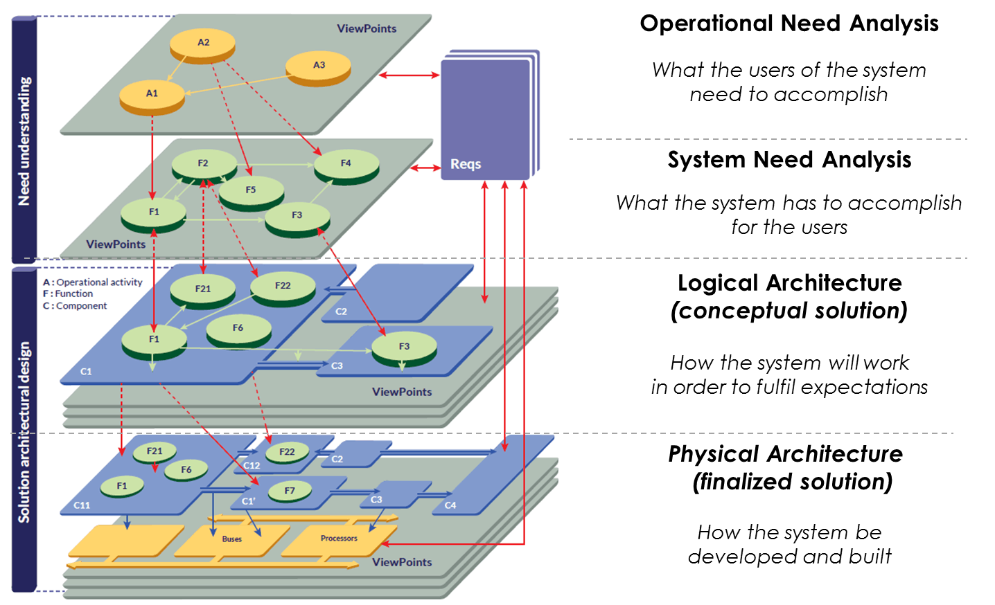
Figure 1: Arcadia engineering perspectives
The Arcadia method intensively relies on functional analysis, which is a very popular technique among systems engineers. Arcadia enforces an approach structured on different engineering perspectives establishing a clear separation between system context and need modeling (operational need analysis and system need analysis) and solution modeling (logical and physical architectures), in accordance with the [IEEE 1220] standard and covering parts of [ISO/IEC/IEEE 15288].
While the Arcadia method itself is tool-agnostic, it requires a modeling workbench to be implemented efficiently. Capella guides systems engineers in applying the Arcadia method and assists them in managing complexity of systems design with automated simplification mechanisms. A model is built for each Arcadia engineering perspective. All models are related by justification links and can be processed as a whole for impact analysis.
Arcadia systems engineering relevant concepts
This section briefly introduces some of the Arcadia concepts that will be exploited in the remaining parts of this paper.
- A system Capability designates the ability of the system to provide a service that supports the achievement of high-level business objectives.
- A Function is an atomic action or operation performed by the system, or by an actor interacting with the system. It is, by convention, named with a verb. A Capability typically requires the collaboration of several Functions. Functional Exchanges connect Functions and express dependencies between the output of the source Function and the input of the target one.
- A Functional Chain is a set of references towards Functions and Functional Exchanges, describing one possible path within the global dataflow. Typical exploitations include the description of an expected behavior of the system in a given context and the expression of non-functional properties on this path (e.g. latency, criticality, confidentiality, redundancy, etc.).
- A Scenario is conceptually close to a Functional Chain in the sense that it illustrates a system behavior in a given context. Compared to Functional Chains, Scenarios provide enriched expression means and in particular, add the concept of time.
- A Logical/Physical Component is a constituent part of the system. It can either be a behavioral component responsible for implementing some of the Functions assigned to the system either be a hosting component, providing resource for behavioral physical components.
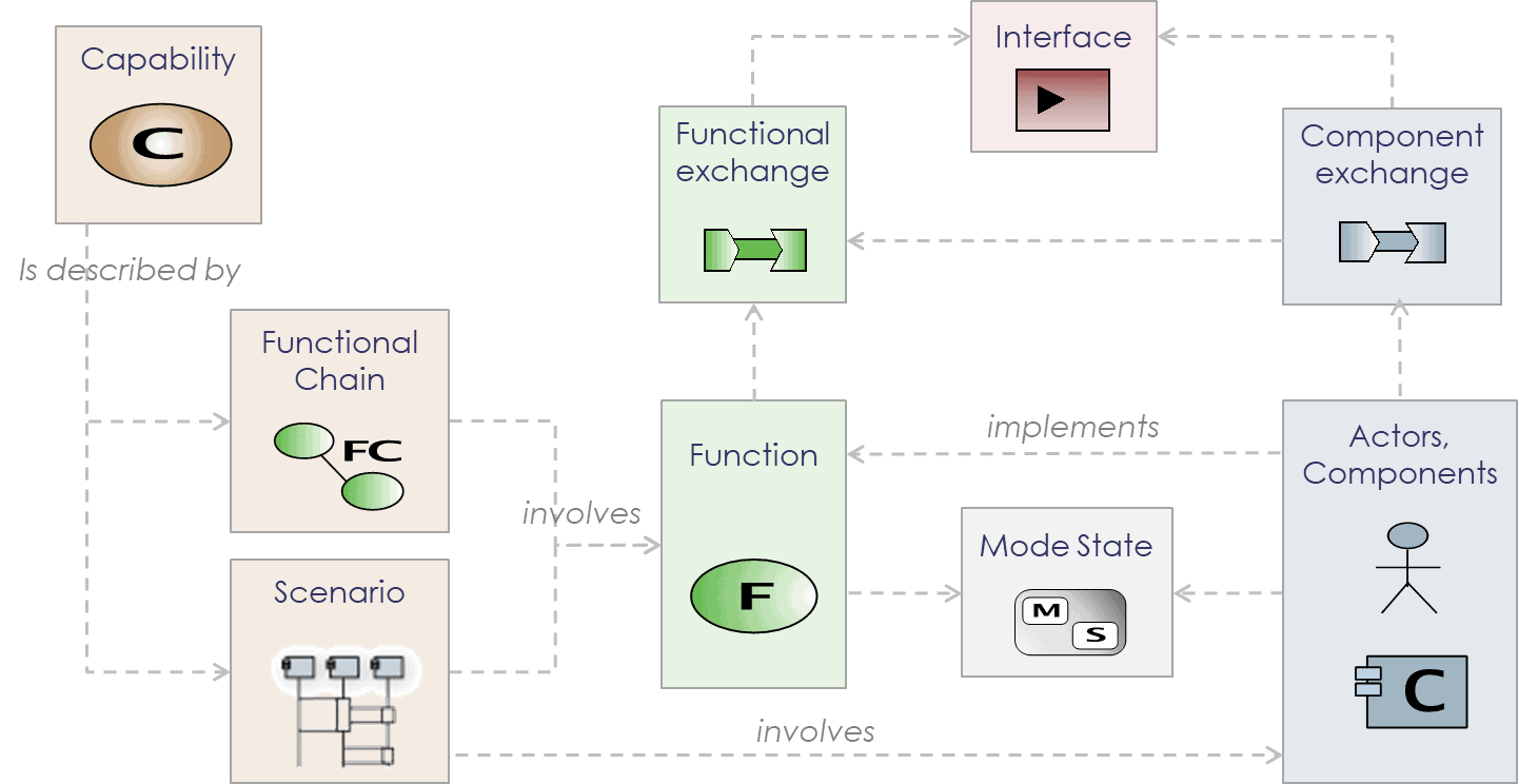
Figure 2: Articulation between Capabilities, Functions, Functional Chains, and Scenarios
The above figure illustrates how Capabilities are illustrated by Scenarios and Functional Chains typically including nominal and degraded cases. Functional Chains and Scenarios involve atomic Functions.
An approach for combining requirements engineering and MBSE
MBSE does not replace traditional methods and best practices. It strengthens them with modeling techniques and it adds rigor in the design activities. MBSE cannot be performed in isolation.
Concept of “model requirement”
While textual requirements are most often written in natural language, models are a means to express information in a way that is well defined and structured, with strict syntax and precise semantics. This level of formalism guarantees consistency (in particular, the uniqueness of data while referenced several times) and enables automated processing. For example, data present or extracted from the model can be used in order to:
- Be injected in other tools to perform additional activities (hardware/software design, specialty engineering, simulation, verification and validation…)
- Perform model validation and ensure completeness, well-formedness, etc.
- Assess design progress (number of complete Capabilities, Functional Chains, etc.)
Models thus provide means to describe need and solution in a form which is shareable, analyzable, and verifiable. Why not talk then about model requirements?
- Functional requirements are likely to be represented by Capabilities, Functions, Functional Exchanges, Functional Chains, Scenarios, Modes, States, etc.
- Interface requirements can be expressed with Functional and Component Exchanges, data structures (Datatypes, Classes, Physical Quantities), Scenarios, Modes, States, etc.
- When possible, non-functional requirements can also be captured through model elements. For example, Functional Chains can carry latency constraints, data can be characterized by confidentiality levels, etc.
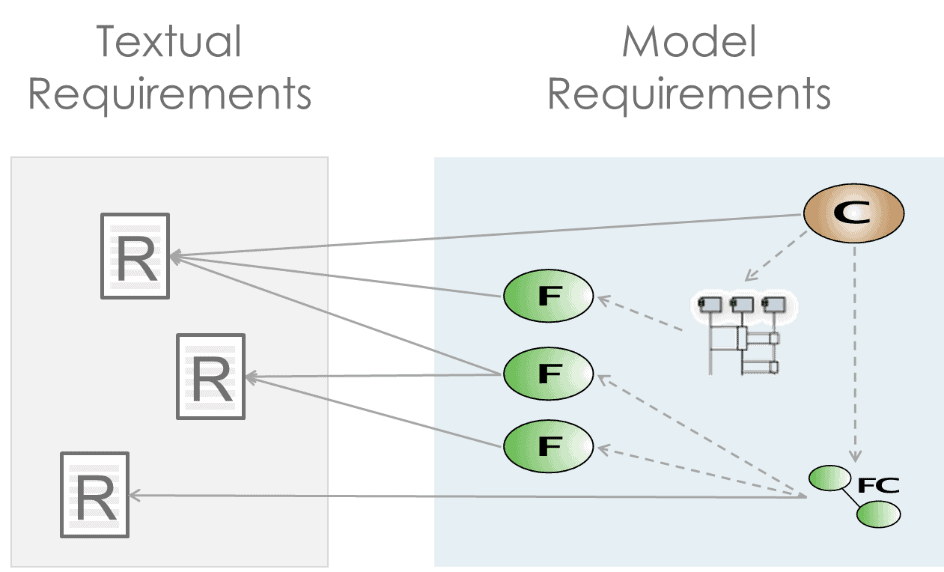
Figure 3: Textual and model requirements
Not all expectations can be expressed or captured in a model. Environmental constraints (temperatures, corrosion, etc.), applicable norms and standards, and required maintenance period, for example, would be difficult to express with model elements. Models are not intended to replace textual requirements. Instead, model elements (including model requirements) and textual requirements complement each other and must typically be related to each other.
Models as parts of the technical contracts
Because they actually contain artifacts that can be considered as requirements, models can and should be used as the central artifacts of the contract between the client and the provider of a system or of a system constituent. The Arcadia clear separation between need and solution perspectives helps implement a workflow combining textual and model requirements.
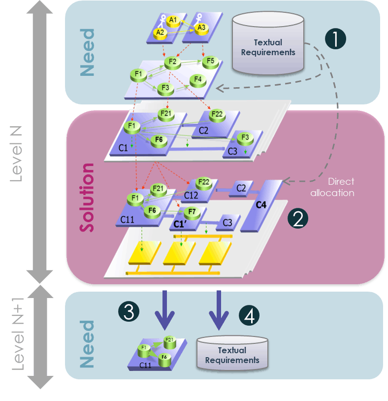
Figure 4: Model and textual requirements in the articulation between engineering levels
Figure 4 above illustrates a typical workflow for architectural design based on the Arcadia engineering method. The numbered items below reference the numbered steps present on the figure.
- Customer high level expectations are described in the Operational Need Analysis perspective where stakeholders and their objectives are modeled using Operational Activities and Processes. Performing the analysis of the customer expectations with a model helps check their consistency and completeness. The System Need Analysis perspective focuses on the expectations on the system itself. The goal in this perspective is to elicit model and textual requirements on the system. Traceability between Operational Need Analysis and System Need Analysis models ensures completeness and paves the ground for later impact analysis.
- Definition of the solution is justified by the System Need Analysis model. Possibly described at different levels of abstraction (Logical Architecture and/or Physical Architecture), the architecture description specifies with the adequate level of detail how the system works and what is expected from each constituent. The goal here is to prepare the contracts for all subsystems and guarantee their proper integration. Instead of simply allocating (or cascading) textual requirements to elements of the Product Breakdown Structure, performing a rigorous, model-based design analysis has multiple benefits. In particular, the solution can be shared easily with all stakeholders: how the system works, what is the contribution of each component, what are the transitions between modes and between states, what are the impacts of modes and states on functional expectations, etc.
- The specification of the subsystems with model requirements comes at no extra cost when the system architecture has been properly modeled. Arcadia advocates a recursive application of the method and Capella provides an automated, iterative transition from system to subsystem (figure below). The context of a given system constituent is entirely computed (anything contributing to the definition of this constituent including allocated Functions, interfacing Components, etc.) and a downstream System Need Analysis model is initialized and maintained based on the evolutions of the system definition. The subsystem Need Analysis Arcadia perspective is a centerpiece of the contract for the downstream engineering team.
A need model helps define the boundaries of the system (or of a system constituent) and describe the “what” in a more rigorous form than with textual requirements. The expectations from the system or from the system constituent can be described with a breakdown of Capabilities involving multiple Functions working together. Each Function is named with a verb, and has well-defined inputs and outputs. It is typically exploited by several Functional Chains, which specify several usage contexts, under the control of Modes and States governing context changes.
Need models can either be derived from an Operational Need Analysis (analysis of the needs of the system stakeholders) or can be derived from an existing architectural/design work (a solution model defined at the upper level of an overarching system).
A solution model typically describes the architecture of the system and provides rationale for this architecture (the “how”). It contains the identification of the subsystems/constituents, the functional and behavioral expectations from each of them, and the description of interfaces. In Arcadia, a strong emphasis is put on the justification of the component interfaces with functional content. Thanks to functional refinement, traceability, and allocation, the contribution of a given constituent to each transverse Functional Chain is defined unambiguously. The contract for the downstream engineering is well-specified and justified.
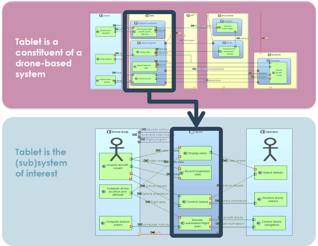
Figure 5: System to subsystem automated transition
- Textual requirements are created when needed, in addition to the model requirements. These requirements can either emerge from the design analysis or result from standard requirements engineering on the part that was not covered by the need model. There can be different strategies but the structure of the model (Capabilities, Functional Chains, etc.) can be a good driver for the structuration of the textual requirements in chapters for example.
- When subcontracting the development of a system constituent to a different organization, legal aspects of contracting often require natural language and thus, textual requirements. In that case, model requirements typically need to be replicated in a textual form (at least partially).
- When working within the same organization and when certification authorities do not prevent it, the scope of textual requirements can be limited to what cannot be efficiently expressed with models (for example, part of non-functional requirements, design or production constraints, etc.).
- Sometimes, functional requirements are necessary to specify additional expected behavior. For example, the way a Function transforms its inputs in outputs is not specified in Arcadia. However, without diving into the detail of the design of a given Function, the upstream engineering team might need to express requirements on the expected treatments. In that case, the model helps elicit and structure textual requirements.
The combination of a model-based approach and automated system to subsystem transition as illustrated above favors co-engineering over the traditional differentiation between customer requirements and system requirements, where the stakeholders of the level N define their own response to the need expressed by stakeholders of the level N-1 (typically using reformulation techniques as explained in the first part of this paper).
Conclusion
The main idea developed in this article is that even in MBSE contexts, requirements still form the backbone of systems engineering practices. However, requirements can either be textual statements or model elements.
Unlike textual requirements written in natural language, model requirements (Capabilities, Functions, etc.) obey strict syntax and semantics that allow them to be automatically processed for analysis, completeness, and consistency. The level of formalism brought by modeling techniques helps improve the transition between systems and subsystems.
Integrating models in the technical contracts for the subsystems is a way to strengthen their specification and to guarantee their good integration in the global solution. Depending on the engineering organization and context, textual requirements can either complete or reflect model requirements.
Considering certain model elements as requirements opens perspectives, in particular in the context of V&V. Test procedures can be aligned with functional chains and scenarios. The content of test campaigns can be defined with sets of model functional artifacts such as Capabilities, Scenarios and Functional Chains, expressing the dynamic use of the system, as specified in Operational and System Need Analysis, and as designed in the solution architecture model. This significant improvement of engineering practices is already implemented on several Thales projects.
References
AFNOR XP Z 67-140, 2018, ‘Information Technology — ARCADIA – Method for systems engineering supported by its conceptual modelling language. General Description. Specification of the engineering definition method and the modelling language.
Capella, 2017, Capella Polarsys Website: https://www.polarsys.org/capella/.
INCOSE, 2014, ‘A World in Motion – Systems Engineering Vision 2015’. Available at https://www.incose.org/products-and-publications/se-vision-2025
ISO/IEC/IEEE 15288, 2015, ‘Systems and software engineering – System life cycle processes’.
IEEE 1220, 2005, IEEE Standard for Application and Management of the Systems Engineering Process
Voirin J-L, 2017, Model-based System and Architecture Engineering with the Arcadia Method, ISTE Press, London & Elsevier, Oxford, 2017
About the Authors
 Stéphane Bonnet is MBSE Senior Coach in Thales Corporate Engineering, where he is in charge of the definition, management, and delivery of engineering services to Thales business units. He holds a PhD in software engineering and is the design authority of Capella, an open source modeling workbench for systems, hardware, and software architectural design. From 2006 to 2015, he has led the development of Capella and has been an active contributor to the Arcadia method. He now dedicates most of his time to evangelization, training, and coaching activities, both within and outside Thales. He helps engineering managers and systems architects implement the MBSE cultural change, with a range of activities spanning from strategic engineering transformation planning to project-dedicated assistance to modeling objectives definition and monitoring. As sponsor of the Thales MBSE community, he animates and coordinates networks of experts from all business units to promote cross-fertilization, to capture operational needs, and to orient the method and workbench evolutions and roadmaps.
 Jean-Luc Voirin is Director, Engineering and Modeling, in Thales Defense Missions Systems business unit and Technical Directorate. He holds an MSc and Engineering Degree from ENST Bretagne, France. His fields of interests include architecture, computing and hardware design, and algorithmic and software design in real-time image synthesis systems. He has been an architect of real-time and near real-time computing and mission systems on civil and mission aircraft and fighters. He is the principal author of the Arcadia method and an active contributor to the definition of methods and tools. He is involved in coaching activities across all Thales business units, in particular on flagship and critical projects.
 Juan Navas is a Systems Architect with 10-years’ experience in performing and implementing Systems Engineering practices in industrial organizations. He has worked on the design and the procurement of instrumentation and control systems and simulation systems for petrochemical plants, nuclear fuel cycle plants, and nuclear power plants. He has lead projects to improve software and systems engineering performance utilizing Model-Based Systems Engineering approaches. He has supported several companies in the aerospace and naval and nuclear energy sectors concerning implementing best engineering and project management practices. He holds a PhD in embedded software computer science (Brest, France), an MSc Degree on control and computer science from MINES ParisTech (Paris, France) and Electronics and Electrical Engineering Degrees from Universidad de Los Andes (Bogota, Colombia).
2.2 Using Graph Model and Viewpoints to Support Maintenance and Consistency of an Architecture Framework
by
Nic Plum
Eclectica Systems Ltd.
Copyright © 2019 Eclectica Systems Ltd.
This work is released under Creative Commons Attribution-NoDerivatives 4.0 International (CC BY-ND 4.0) license (see https://creativecommons.org/licenses/by-nd/4.0/). You are free to share, copy and redistribute the material in any medium or format for any purpose, even commercially, under the following terms:
Attribution: You must give appropriate credit, provide a link to the license, and indicate if changes were made. You may do so in any reasonable manner, but not in any way that suggests the licensor endorses you or your use.
No Derivatives — If you remix, transform, or build upon the material, you may not distribute the modified material (permission needs to be sought).
No additional restrictions — You may not apply legal terms or technological measures that legally restrict others from doing anything the license permits
Introduction
Keeping an architecture framework small and consistent is time-consuming. So is checking for errors across multiple documents. What follows is a short description of some of the work in describing an open source architecture framework (TRAK), its metamodel, its viewpoints (specifications for views in ISO/IEC/IEEE 42010:2011 [1] terminology) and its implementation using the Universal Modelling Language (UML). The task has been aided by the development of a set of viewpoints to structure the description of TRAK. The viewpoints can be applied to any metamodel and architecture framework. The model has been created as a set of graphs held within a Neo4J [2] graph database and views have been implemented as graph queries using the CYPHER [3] path-following query language.
This article covers:
- TRAK – a quick overview of the TRAK architecture framework and the problem of maintaining its definition and implementations.
- The modelling of TRAK.
- The viewpoints used to describe the typical workflow:
- Model Configuration & Change Viewpoint
- Metamodel Element Structure Definition Viewpoint
- Metamodel Tuple Definition Viewpoint
- Viewpoint Definition Viewpoint
- ADL Implementation Viewpoint
The description of each provides the tuples used in each viewpoint and an example of some of the output views against the model of TRAK.
- TRAK
TRAK is an open source architecture framework aimed at systems engineers that complies with the international standard for architecture description, ISO/IEC/IEEE 42010:2011.
Originally released in 2010 it is specified by 3 documents – the metamodel [4], the viewpoints [5] that use the tuples from the metamodel, and the overall requirements [6]. These specifications are solution-independent, in keeping with systems engineering practice. This means that the TRAK metamodel specification contains no constructs needed to construct it in a particular notation. This is different from the OMG specifications for UML or SysML which specify how to implement the notations.
For TRAK there is a separate implementation specification that specifies how to implement the TRAK specifications. There are also two Universal Modelling Language (UML) model implementations: a general UML profile [7] and a specific one [8] for the Sparx Systems Enterprise Architect UML modelling tool [9].
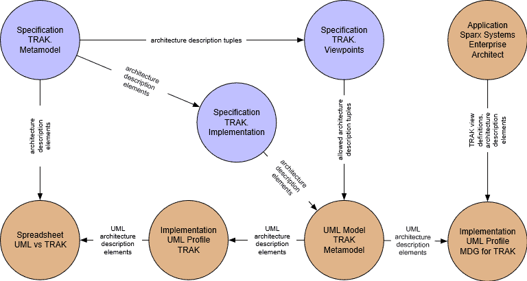 There is also a centrally-held spreadsheet that maps the elements used in the UML profile against the tuples in the TRAK metamodel and therefore how much of each of the 24 TRAK viewpoints can be represented using the particular UML implementation. This spreadsheet has over 500 rows and is manually maintained.
Figure 1: Dependencies between the Definition of TRAK and Its Implementation
These artifacts are all interdependent (Figure 1); maintaining consistency and assessing impact is essential to both the specification and implementation of the architecture framework.
TRAK is unusual in many respects:
- Systems engineering has been applied to the definition and the system design of the architecture framework even to the extent of considering human factors qualities such as affordance, visibility, and feedback; and the interaction between the user/modeller, the definition, and the implementation in a tool. Some of these interactions may be unwanted; sometimes it requires anticipating how the user may short-circuit that which was intended in order to save time (at the expense of the information captured in the architecture description). A whole-system approach is also needed in order to design something that requires the minimum amount of effort to maintain. This is required because TRAK as an open-source effort has no budget and depends on good will and ‘spare time’ effort.
- The allowed and the minimum content of each TRAK view is specified. This is only possible because TRAK Viewpoints are defined using tuples or graphs which enables paths to be uniquely specified. The customary approach using only nodes produces ambiguous results and therefore inconsistency.
- TRAK doesn’t allow any node elements which aren’t connected by a relationship (“orphans”). This is because an isolated node tells us nothing – it cannot describe any architectural relationship and therefore it isn’t valid for architecture description. The smallest unit of architecture description is a tuple, i.e. node – relationship – node. This means that TRAK views can be read as a set of sentences. Indeed, a text-based description is an allowable implementation.
- TRAK requires the types/labels for the node and connector elements to be visible (otherwise they couldn’t be read as sentences and the meaning wouldn’t be explicit, thus subject to individual interpretation and error).
- TRAK specifies consistency rules that apply across the set of views in the architecture description.
- TRAK specifies some rules that affect the order in which tuples in the TRAK views can be created. For example, TRAK requires that one first identify an interface before characterizing it (SV-02 Solution Resource Interaction View). It also requires that a Claim (about anything in the TRAK architecture description) is supported by one or more Arguments, which in turn are supported by one or more Evidence elements before asserting that the Claim is proven (MV-04 Assurance View).
- TRAK has always complied with the international standard for architecture description, ISO/IEC/IEEE 42010:2011.
- Maintaining an Architecture Framework
The effort spent maintaining consistency in an architecture framework such as TRAK depends on the size of the metamodel, the number of viewpoint definitions, and their interconnectedness.
TRAK has a small metamodel in terms of the number of nodes. The nodes are highly connected. It also has roughly half the number of viewpoints of an architecture framework such as the Ministry of Defense Architecture Framework (MODAF) now subsumed into the NATO Architecture Framework (NAF) [10]. Even so manual maintenance is not only time-consuming but error prone and therefore a model-based approach is needed to support the production of the various specification documents.
Modeling TRAK Itself
In order to aid the consistency of the various parts of the definition of the TRAK architecture framework, a model / architecture description has been created to describe TRAK which includes:
- TRAK metamodel elements (nodes, connectors, properties, and allowed values)
- TRAK metamodel tuples
- TRAK viewpoint definitions in terms of allowed and minimum acceptable content using the metamodel tuples
- Implementation of the TRAK metamodel using an Architecture Description Language (ADL) such as the UML (via an externally generated UML profile)
This in turn required its own set of viewpoint definitions to describe a metamodel and the architecture framework’s viewpoints.
There are many reasons to prefer using graphs:
- Since architecture according to ISO/IEC/IEEE 42010 is embodied in elements and relationships, this by definition requires tuples (graphs) to describe it (the minimum unit of architecture description is an architecture description tuple). Architecture description therefore requires a relationship-centric notation rather than an object-centric one.
- They can be read as sentences.
- They form testable assertions.
- They enable path-following queries to be constructed and test for closure of loops – essential for consistency rules.
It is fitting that an architecture framework that defines content using graphs can itself be described using graphs where the views are the results of a graph path-following query against the model.
Being able to return the complete lifecycle of a model element as a graph (Model Configuration & Change Viewpoint) held within the same model is useful.
- Modeling Using a Graph Database
Since TRAK uses graphs and the viewpoint definitions use graphs, it makes sense to describe TRAK using graphs and implement this in a graph database. This is the most direct form of model, and a graph database such as Neo4J is able to natively store and process graphs. There are no underlying tables.
Neo4J uses CYPHER as its query language. The queries match a pattern which is a path traversal through the graph model:
//List changes and change requests for TRAK Viewpoints
//First find every change request
MATCH (chg:Change {project:’trakviewpoints’})
// then match any changes that respond to these change requests
OPTIONAL MATCH (cr:Change_Request)<-[:`RESPONDS TO`]-(chg)
// then match changes to the particular version of the TRAK metamodel specification
OPTIONAL MATCH (chg)<-[:INCLUDES]-(ver:Version)-[:`IS VERSION OF`]->(vp_spec:Standard {`DCMI identifier`:’TRAK00001′})
//return the results as a table with the document identifier, title, and details of the change and change request
RETURN vp_spec.`DCMI identifier`,vp_spec.`DCMI title`, chg.identifier,chg.name,cr.identifier,cr.title,cr.`date created`
ORDER BY chg.identifier DESC
Note that Neo4J is a directed graph database – relationships have a specified direction and this is specified in the query using -[:RELATIONSHIP_NAME]-> Unlike a SQL database it is just as easy to follow a path in any direction e.g.:
(chg)<-[:INCLUDES]-(ver:Version)-[:`IS VERSION OF`]->(vp_spec:Standard {`DCMI identifier`:’TRAK00001′})
The metamodel viewpoint definitions include examples of views created using the CYPHER query language against a Neo4J graph database which holds the model of TRAK. All of the example figures are the direct output of the Neo4J database.
Viewpoints
One of the early needs was to be able to describe the change in parts of the definition of TRAK over time. This therefore required a way of describing versions, change requests, and the addition-to or the removal-from elements. The resulting Model Configuration and Change Viewpoint can not only be applied to a metamodel but to any model. Furthermore the record of change can be held within the same model rather than in a separate tool.
Figure 2: Viewpoint Configuration Change
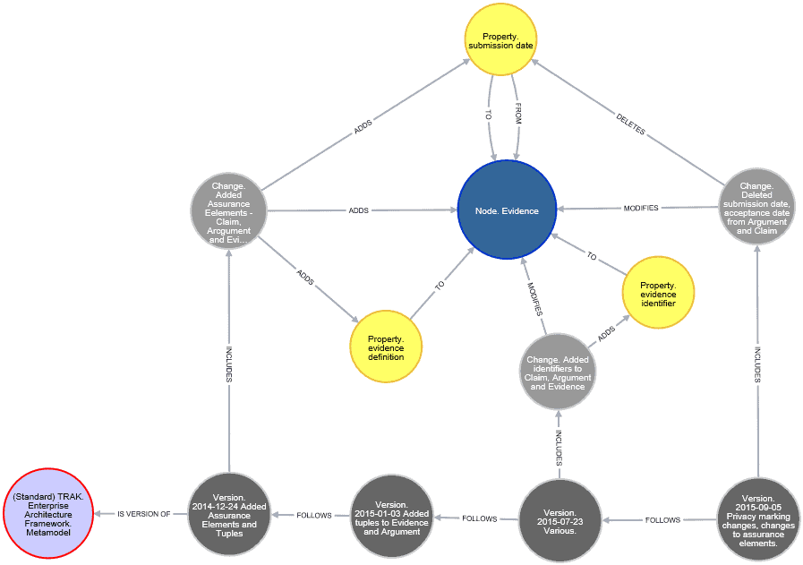 Using a graph query, it is possible to then describe the entire lifecycle of a model element. Figure 3 describes the creation of the Evidence metamodel element and changes made to it in the context of versions of the TRAK Metamodel specification.
Figure 3: TRAK Evidence Metamodel Element Lifecycle
A means of describing the structure of a metamodel element is provided by the Metamodel Element Structure Definition Viewpoint (Figure 4). It provides the ability to describe element properties and inheritance from other metamodel elements.
Figure 4: Metamodel Element Structure Definition Viewpoint Tuples
The description of the System element in the TRAK metamodel (Figure 5) shows how the System element inherits from Resource (which includes Organization, Role, Job, System, Software, and Physical elements), Safety-Monitored Element (which includes Resource and Function and allows a safety integrity level to be assigned) and the parent Architecture Description Element. In TRAK an Architecture Description Element is any element that may appear in a view (as opposed to elements such as Resource which are used to manage inheritance or used in the design of TRAK).
Figure 5: Structure of the TRAK System Metamodel Element
- Metamodel Tuple Definition Viewpoint
Having defined the metamodel elements, the next step is to define the metamodel tuples formed from the combination of one or more nodes with at least one connector. This is described using the Metamodel Tuple Definition Viewpoint. The direction of a relationship is defined using Architecture Description Tuple – STARTS AT → / -FINISHES AT→ Node/Connector. The — STARTS WITH → followed by – THEN → construct allows a compound tuple (2 or more tuples) to be defined. This supports the definition of rules for minimum acceptable content using the Viewpoint Definition Viewpoint.
Figure 6: Metamodel Tuple Definition Viewpoint Tuples
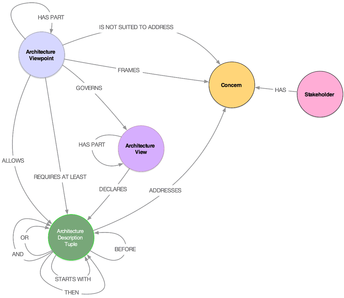 Having defined the metamodel tuples, it is then possible to define the viewpoints that use these tuples to address a defined set of concerns in accordance with the conceptual model in ISO/IEC/IEEE 42010:2011. An ‘anti-concerns’ can be defined using the – IS NOT SUITED TO ADDRESS → relationship.
Figure 7: Viewpoint Definition Viewpoint Tuples
The Viewpoint Definition Viewpoint is split into two steps: definition of the concerns addressed, and definition of the tuples addressing the concerns. This provides the ability to check that every tuple is needed i.e. a justification for the tuple by reason of responding to the concern that requires it. Any tuples not linked can be identified and linked or removed. It also allows the potential impact of changing a concern to be identified. The consistency of the viewpoint definition can be checked using the ‘Architecture Viewpoint – FRAMES -> Concern <- ADDRESSES – Architecture Description Tuple <- REQUIRES AT LEAST – Architecture Viewpoint’ path. This provides a check that the tuples addressing the viewpoint concerns form part of the minimum acceptable view content. The following is a CYPHER graph query that checks this:
//
// Quality – Identify tuples required to address viewpoint concerns missing from well-formedness criteria
//
MATCH (vp:Architecture_Viewpoint:TRAK {name:’MVp-04 Assurance’})-[:FRAMES]->(conc:Concern)<-[:ADDRESSES]-(adt:Architecture_Description_Tuple)
WHERE NOT (vp)-[:`REQUIRES AT LEAST`]->(adt)
RETURN adt.name AS `Tuples Missing from Well-Formedness Definition`
which returns Table 1:
Table 1: Result of CYPHER Query to Test Well-Formedness of TRAK MVp-04 Assurance Viewpoint Definition (in the model of TRAK)
|
Tuples Missing from Well-Formedness Definition |
|---|
|
Evidence has part Evidence |
|
Claim has part Claim |
|
Argument has part Argument |
|
Argument opposes Argument |
So far, the viewpoints have been concerned with the definition of a metamodel and the viewpoints that use the metamodel. There are usually many possible ways of implementing a solution-independent definition of a metamodel, even if the same notation is used, for example using a different choice of UML connector to represent a TRAK metamodel connector. The mapping between the ADL metamodel elements and the architecture framework metamodel is described using the ADL Implementation Viewpoint.
Figure 8: ADL Implementation Viewpoint Tuples
A metamodel may be represented by an Architecture Description language such as the UML, Systems Modelling Language (SysML), or ArchiMate. The suitability of this representation depends on the concepts within the ADL and the tuples that exist in the ADL metamodel. It also depends on whether the concept is represented by a node or connector, since a tuple is formed from 2 nodes and a connector (node – connector – node) or a single node with a relationship to itself (e.g., Physical HAS PART Physical). The comparison of tuples can then be used to establish how much of each viewpoint the ADL is able to represent. The tuples that can be represented using the ADL affect whether particular viewpoint concerns can be addressed (using the ‘Architecture Description Tuple ADDRESSES Concern’ established in the Viewpoint Definition Viewpoint). If particular concerns are essential to the architecture description process and the ADL is partially or completely unable to represent one or more tuples addressing these concerns, a decision has to be made whether to choose an alternative ADL or use multiple ADLs. The viewpoint provides a basis for an objective assessment.
As an example, Figure 7 provides 10 random UML metamodel elements from the UML profile for TRAK and the TRAK metamodel elements represented by them.
//
//Return 10 (random) elements from the UML profile for TRAK implementation and the TRAK elements represented
//
MATCH (TRAK_element)<-[:`TO REPRESENT`]-(adl_element)-[:`IS A`*..]->(adl_parent)<-[:`HAS PART`]-(adl_metamodel:Metamodel {name:’UML’})
OPTIONAL MATCH (imp:Implementation {name:’UML profile for TRAK’})-[:USES]->(adl_element)
WITH imp.name AS Implementation,adl_element.name AS `ADL Element` ,adl_parent.name AS `ADL Parent`,labels(adl_parent) AS `ADL Element Type`,TRAK_element.name AS `TRAK Element`,labels(TRAK_element) AS `TRAK Element Type`,rand() AS number
ORDER BY number
LIMIT 10
RETURN Implementation, `ADL Element`, `ADL Parent`, `ADL Element Type`, `TRAK Element`, `TRAK Element Type`
which returns Table 2:
Table 2: Partial Description of UML Metamodel Elements Used to Represent TRAK Metamodel Elements
|
Implementation |
ADL Element |
ADL Parent |
ADL Element Type |
TRAK Element |
TRAK Element Type |
|---|---|---|---|---|---|
|
UML profile for TRAK |
trakumlprofile::Milestone |
UML:: Class |
Node, UML |
Milestone |
TRAK, Node |
|
trakumlprofile::Metric |
UML:: Class |
Node, UML |
Metric |
TRAK, Node |
|
|
trakumlprofile:: Threat |
UML: Class |
Node, UML |
Threat |
TRAK, Node |
|
|
trakumlprofile:: triggers |
UML: Dependency |
Connector, UML |
triggers |
TRAK, Connector |
|
|
trakumlprofile:: impacts on |
UML: Association |
Connector, UML |
impacts on |
TRAK, Connector |
|
|
trakumlprofile:: caused by |
UML: Dependency |
Connector, UML |
caused by |
TRAK, Connector |
|
|
trakumlprofile:: Risk |
UML: Event |
Node, UML |
Risk |
TRAK, Node |
|
|
trakumlprofile:: Human Resource |
UML: ActivityPartition |
Node, UML |
Human Resource |
TRAK, Node |
|
|
trakumlprofile:: addresses |
UML: Dependency |
Connector, UML |
addresses |
TRAK, Connector |
|
|
trakumlprofile:: Job |
UML: Class |
Node, UML |
Job |
TRAK, Node |
Conclusion
This has been a spare time activity for the last three years. It will continue to evolve. Using the entire set of tuples within the model of TRAK, it has been possible to check for errors in definition. Some of the output in the specification documents is now produced directly from the model. For the first time, it is now possible to transform the XMI output from the Sparx EA UML models and compare this directly with the definition of TRAK within the Neo4J database, and validate the implementation. Previously this was a tortuous process involving manual inspection.
The use of graphs and the Neo4J CYPHER query language make it relatively straightforward to produce complex views that would otherwise require too many table joins in a SQL database to be feasible. The path-following syntax is a natural way to describe view content and rules and is relatively easy to understand. Support for recursive pattern matching makes it easy to retrieve a hierarchy in a couple of lines, for example to verify TRAK against the requirements in ISO/IEC/IEEE 42010:2011 using TRAK MV-04 Assurance views (possibly the subject of a future article).
The work continues. The most recent addition to the viewpoints allows for a description of dependencies between views to allow for sequencing rules that affect the order in which views might be created, for example, to declare a particular metamodel element before using it elsewhere (much like UML classes are defined first in a Class diagram).
The full text report is available via ResearchGate at: https://www.researchgate.net/publication/335176248_Architecture_Description_Viewpoints_Metamodel_Description_Implementation_and_Model_Changes
References
[1] ISO/IEC/IEEE 42010: 2011: Systems and Software Engineering, Architecture Description. International Standards Organization, 2011. Available at https://standards.ieee.org/standard/42010-2011.html.
[2] Neo4j Graph Platform, Neo4j Graph Database Platform. [Online]. Available: https://neo4j.com/.
[3] Cypher Graph Query Language, Neo4j Graph Database Platform. https://neo4j.com/cypher-graph-query-language/.
[4] N. Plum. TRAK. Enterprise Architecture Framework. Metamodel, TRAK00002, January 2017. https://sourceforge.net/projects/trakmetamodel/.
[5] N. Plum. TRAK. Enterprise Architecture Framework. Viewpoints, TRAK00001, January 2016. https://sourceforge.net/projects/trakviewpoints/.
[6] N. Plum. TRAK. Enterprise Architecture Framework, TRAK00004, January 2016. https://sourceforge.net/projects/trak/.
[7] TRAK UML Profile, SourceForge. [Online]. Available: https://sourceforge.net/projects/trakumlprofile/.
[8] Sparx EA – MDG for TRAK, SourceForge. [Online]. Available: https://sourceforge.net/projects/mdgfortrak/.
[9] ‘Sparx Systems Enterprise Architect UML Modelling Tool’. [Online]. Available: https://sparxsystems.com/products/ea/index.html.
[10] NATO Architecture Framework. Version 4. Architecture Capability Team, January 2018. Available at https://www.nato.int/cps/en/natohq/topics_157575.htm.
[11] N. Plum, Architecture Description Viewpoints. Metamodel Description, Implementation, and Model Changes, Eclectica Systems Ltd, 3736126–001, Aug. 2019. https://www.researchgate.net/publication/335176248_Architecture_Description_Viewpoints_Metamodel_Description_Implementation_and_Model_Changes
3. Additional Articles
3.1 Input from the INCOSE Europe, Middle-East, and Africa (EMEA) Sector and the State of the EMEA Union
by
Paul Schreinemakers
EMEA Sector Director
I’m proud to be able to state that the EMEA Sector of INCOSE is a steadily growing and very healthy Sector within the INCOSE community. Where 25 years ago (1994) the UK Chapter was the first non-American Chapter to see the light in the INCOSE family, followed by the Netherlands (1996), France (1998), Germany (1998) and many others, EMEA membership now covers 18 Chapters, representing even many more countries within the Sector. We continue to grow our footprint in the Sector and this point in time a Chapter is emerging in Belgium.
The EMEA Sector now covers close to 40% of all of INCOSE’s individual members. Some of the Chapters, like the United Kingdom Chapter, GfSE (Germany), AFIS (France) and the Netherlands can be counted among the largest of all of INCOSE. Actually, with almost 950 members the UK Chapter is the largest Chapter in INCOSE.
With the large representation of INCOSE in the EMEA Sector, it’s no wonder that many activities take place across the Sector. That is both on Chapter- and Sector-wide levels. In the Sector and across groupings of Chapters the following activities take place on a regular basis.
EMEASEC: this event is the bi-annual EMEA Systems Engineering Conference (EMEASEC), providing papers, panels, tutorials, and high-level keynote speakers. The conference has proven to be a successful and well-visited event with between 200 and 300 attendees. The two-day event has been presented across the different continents which EMEA spans, visiting many cities including Munich, Toulouse, Edinburgh, Stockholm, and Cape Town. Over the last 1 ½ decades, the INCOSE International Symposium has come to EMEA every 4 years. That has provided an excellent opportunity to coincide the EMEASEC with the International Symposium for each of those occasions, as it will during next year’s IS2020 in Cape Town. The location of the 2022 EMEASEC is yet to be decided upon by the EMEA Chapters.
The EMEA Workshop is a second flagship event within our sector. This workshop also occurs on a bi-annual basis and focusses on the Working Groups that have specific interest in the EMEA arena. The most recent EMEA Workshop took place in Utrecht (Netherlands), early October 2019. This event attracted 150 participants and was sold-out three weeks before the starting date. The working groups that met at this event were:
- Automotive
- Architecture
- PM-SE Integration
- Simulation
- SME & SE
- Future of Systems Engineering
- Human System Integration
- Competency, Reliability Engineering
- Product Line Engineering and System Thinking
- Competency, Configuration Management
- System of Systems
- Young INCOSE
- Knowledge Based Engineering
- System Integration in Rail
- MBSE
- Oil & Gas
During the two-day event, we had five parallel sessions. Each track had one session in the morning and one in the afternoon, spanning two and one-half hours each. As an experiment, each session had a facilitator assisting the group in focusing on the topics to be addressed, being creative in reaching results, and making sure the sessions were inclusive to all participants. Secondly, each of the working groups’ sessions was encouraged to generate a poster reporting on the results of the session in a graphical rather than a text-based manner. These approaches proved to be very successful and were appreciated by the audience.
The EMEA Workshop provides an excellent platform for INCOSE members residing in Europe, Middle East, and Africa who are not able to travel to the International Symposium or Workshop; but who want to share their experience and knowledge of Systems Engineering, as well as obtain knowledge from others in the field or working in different domains.
For this special occasion, a Foundation for Systems Engineering (F4SE) summit was organized in parallel to the EMEA Workshop’s first day. For this summit, 18 participants from all over the globe traveled to Utrecht to discuss the path forward for the definition of the Foundation for Systems Engineering. This F4SE project is one of the projects of the Future of Systems Engineering (FuSE) initiative that has been initiated by INCOSE and several other Systems organizations. The results from this Summit were reported back to the EMEA Workshop audience and will also be shared with the wider Systems community.
In addition to EMEA wide events including the Workshop and Conference, the Chapters in our Sector are very active. This is the case throughout the entire Sector, whether it concerns a smaller or very large Chapter. As a very special occasion, the UK Chapter held the annual conference (ASEC) from 19-20 November 2019 in Leeds. With the 2019 ASEC, the UK Chapter celebrated 25th anniversary. This is a key milestone for our largest Chapter, that is strong as ever, and an excellent example of the added value that INCOSE brings to its membership, society, and the future of our planet.
As you can surely tell from the listing of Chapters in the first paragraph, more 25th anniversaries are coming-up during the next few years!
Another activity that is undertaken by some of the Chapters is to translate or support the translation of the INCOSE Systems Engineering Handbook v4. Currently, we are looking forward to translations of the handbook into Spanish, German, and French. This is done in close collaboration with Wiley, the official publisher of the INCOSE SE Handbook.
During the recent election cycle Lucio Tirone was elected to take over my position of EMEA Sector Director. I’m delighted that Lucio will do so at the IW2020. The EMEA Sector will be in very capable hands.
It is my privilege to serve as the Director of the INCOSE Europe, Middle-East, and Africa Sector. I’ve made many friendships I will always treasure!
EDITORIAL
3.2 From the Beginning
by
Randall C. Iliff
PPI Principal Consultant and Training Presenter
Introduction
First, I’d like to note that this is an opinion piece rather than a technical article. You won’t learn the latest MBSE technique, discover a new SE tool, or advance your knowledge of formal SE terminology. Those are all important of course, but having been part of INCOSE since the beginning (I’m member #48) and had the experience of performing SE across a very wide range of effort in many different industries gives me view of SE that is likely different than most.
I’m grateful to PPI for the opportunity to share these ideas, impertinent and otherwise, but please remember that they are strictly my own thoughts and not to be viewed as representing PPI or any other organization. Hereby appropriately disclaimed, and in the spirit of service to the SE community, I’d like to share some of those views with you today.
I’ll share why I helped found and build INCOSE and remain an active member almost 30 years later, but I’ll also point out what I consider to be significant challenges and untapped opportunities. In the process I hope to remind you why you became interested in SE, and possibly inspire you to put at least a little of your passion to work helping others.
Why?
Human motivation seldom arises from a single variable, and I’ll freely admit a combination of personal and professional circumstances probably had a lot to do with joining INCOSE. Still, the main reasons were clear to me at the time and remain so to this day.
At that point in my career I had spent over ten years using systems engineering logic to develop highly complex weapon systems – cheery little things like cruise missiles, ICBM systems, and WWIII simulation facilities for the Strategic Defense Initiative. My appreciation for the power of the SE logic was profound, but I was growing increasingly uncomfortable with the thought of devoting my remaining life energy designing even “really cool” ways for people to kill each other more efficiently.
This was the dawn of the commercial system era, and everywhere I looked I saw equivalent system challenges. What I did not see was any meaningful awareness in those communities of the body of knowledge needed to address system level challenges. Instead of learning from the Mil/Aero sector, commercial industries such as Automotive, Telecom, Medical, Computer Hardware / Software and many others were independently “reinventing” their own body of methods from scratch.
It occurred to me that what the commercial sector needed wasn’t the “mature” version of SE, but rather access to the enabling principles that were present in Mil/Aero long before the term “system engineering” showed up in any job title or on any organizational chart. This insight offered a compelling opportunity to shift my career path.
I had also been on the planet long enough to realize that human progress is neither constant nor certain, and two emerging trends that we’ll discuss shortly concerned me greatly. The combination of “carrot” in the form of a renewed and enlarged career path, together with a “stick” in the form of living in a more dangerous world if I didn’t help defend it, offered a clear case for me to act.
But what can one individual do in such circumstances? Discovering that there were others out there like me, and the possibility that we might work together to accomplish something meaningful, was all the incentive I needed to join INCOSE!
Serious Challenges
In the introduction I mentioned two huge concerns that stood out to me. The first realization was how poorly prepared the average person was to live in an era in which everything of consequence now took place at a system level. Those with training and experience could easily see the patterns of cause and effect arising from a set of interacting elements – those without such a background found them as invisible as radio waves. Cause and effect were no longer linked in any meaningful way, and the results were driven more by superstition than science.
Over time I’ve come to call this phenomenon “system illiteracy” and find that it divides society into participants and non-participants in a way that closely matches that of written language skills. Below is a figure summarizing the shift in classic literacy over the last two centuries:

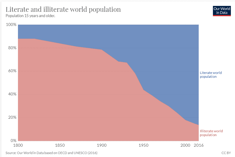
It is nearly impossible today to imagine a meaningful life, let alone a career, without an underlying foundation of basic language skills. Culture, philosophy, literature, history, entertainment, and even current news are all largely unavailable to a person without written language skills.
A tiny but growing body of systems engineers and others in professional settings are now wonderfully fluent in systems thought and awareness. An even tinier number have even mastered Model Based System Engineering (MBSE).
At the same time though, average system literacy has plummeted. People evolve slowly, technology evolves rapidly, and the gap is now larger than at any point in recorded history.
Imagine that same chart, but with the trend reversed and compressed into a period of less than twenty years, and you gain some sense of the sudden division taking place throughout society. Two centuries ago a person’s social status and opportunities were largely determined by the ability to read and write, today those opportunities are driven by system thinking ability.
While life is clearly becoming more and more difficult for those left behind, it’s important to realize that the “system literate” are not safe either. The resulting social pressures are far more dangerous than most people realize, and world history is filled with examples of unpleasant ways that societies deal with radical disparity in income and status.
Even more fundamental, human cognition is simply not “designed” to function in an environment in which people are exposed to exponentially growing levels of complexity. Without suitable logic structures to assist and defend us, overload leads to narrower focus and eventually complete disengagement.
This results in a phenomenon that I call the “Imagination / Mastery Chasm” and increasingly separates what a few humans can now imagine and build from what the rest of humanity can truly understand, control, and maintain. We are rapidly losing the “herd immunity” that protects modern civilization from self-destructive behavior.
The second realization was how easily leaders in industry and government could exploit this weakness in pursuit of narrow, short-term gain. What a system engineer would disparagingly call sub-optimization had suddenly become “brilliant management” and a ticket to instant riches in the investment and corporate leadership world.
Assessing all benefit versus all cost over an extended period of time yields a true and sustainable measure of value. It is the secret of how companies like General Motors, Motorola, GE, Westinghouse, RCA and many others rose to success over a period of many decades, and also the secret of how they could be so quickly destroyed.
The shorter the time interval and more narrow the view the less real information it contains.
Partial benefit, partial cost, and partial timeline are meaningless from a system perspective but extremely useful if you wish to hijack decision making and fool shareholders. Decisions that were once made based on the entire future of the company gradually narrowed to five year plans, then annual decisions, then quarterly results, and are now taking place by algorithms in the stock market over mere billionths of a second.
My term for this trend is “Divide by Zero Management” and in my view it is as much a fatal error in business as it is in computational design.
The equivalent in societal terms also exists of course. In that context I use the term “Divide by Zero Governance” to describe deliberately applying the same “anti-system practices” to the task of breaking large cohesive communities into smaller and smaller interest groups. Once stripped of collective power and awareness, small interest groups can then be easily manipulated into behaviors that are absolutely inconsistent with their long term best interest.
Ok, Breathe!
That’s a lot of serious, somewhat depressing stuff crammed into a few paragraphs. Take a moment to realize that the world has always had challenges, and yet somehow here we are thousands of years later still worrying about everything the ancients promised would destroy civilization within a generation or two…
My point is simply that the same challenges that were motivations to me 30 years ago not only still exist, but have become even more pressing reasons to be active in Systems Engineering!
Commercial Potential
Fortunately the opportunity side of the balance sheet has also remained strong and grown exponentially. For many years I served as VP at a company that executed roughly 250 commercial sector development projects per year, ranging in complexity from designing the simplest plastic product container to creating advanced medical imaging devices and even helping to design a cubic kilometer neutrino telescope now operating at the South Pole. The company had worked with over 2,500 companies to create products in every imaginable sector, including medical, scientific, transportation, telecom, and consumer markets.
In every one of those engagements SE principles contributed value – in several cases unlocking access to billion dollar markets – but virtually none of our clients had even heard the term “systems engineering” prior to working with us. They might have been doing things that fall within portions of the SE spectrum, but they universally lacked a “system approach” to the conduct of those tasks and thus missed the majority of potential benefit.
The handful who did know the term “system engineering” feared it, and we typically found it a better business practice to hide our use of SE rather than promote it. Although a few became curious after the fact and asked how we obtained such remarkable results, in all cases the “spark” failed to take within their own organizations and interest in SE quickly died out.
The essential connection they were unable to properly recognize is that SE offers value anywhere development is taking place – in other words whenever decisions are being made that modify, create, or sustain elements that are organized to deliver otherwise unavailable emergent properties. SE is also a remarkably efficient tool for “copying and pasting” patterns of solution from one industry to another, and thus was responsible for generating stunning quantities of Intellectual Property (IP) in addition to a long list of products our clients could take to market.
Basic SE practices – implemented using no tool other than Microsoft Office – were sufficient to enable the $300M IceCube Neutrino Telescope project to be delivered on time, on budget, and in excess of required technical performance. Using simple system logic, a client’s single product idea was revealed to actually be the opening to an entire industry of related products. By conservative estimate, an investment stream of less than $15 – 20 Million routinely generated over $2 Billion in new product value for our clients every year. What other legal investment can deliver a 100:1 payback on an annual basis?
I remain dumbfounded by the immense irony of hiding the use of something that routinely contributed the bulk of our development success, and which arguably offered the most attractive rate of return available to anyone engaged in New Product Development (NPD).
This remarkable barrier to enlightenment is partly attributable to an ongoing challenge on behalf of INCOSE and others to meaningfully communicate the benefits of SE outside our own membership, but it is also important to realize that nearly all of our clients primarily identified themselves as manufacturers. Starting from that reference framework, they viewed virtually everything as a “cost of goods sold” to be minimized, and thus only engaged in development when forced to do so by market pressure. Even then spending less was more important than getting more.
The problem is that the production space is essentially mature. Anyone, anywhere, can set up and run a factory. According to the iso.org website, over one million companies and organizations in 170 countries are now certified to ISO 9001.
Despite all that interest in quality, even the best product or process cannot exceed perfection. Thus the only competitive variable remaining in a production setting is to minimize cost. When you want to make many copies of a product as efficiently as possible that logic makes great sense – the only thing that can happen is to lose value en route to market.
Development though, is very different. The relationship between cost and outcome now has upside as well as loss and must be thought of as in investment to be optimized rather than a cost to be reduced. The misapplication of production logic to the development space blinds the vast majority of organizations and companies from making the investment in excellence.
Despite nearly worldwide excellence in production, the design space remains incredibly primitive and arguably delivers only a tiny fraction of the potential return available from the market. Investments in production are limited by remaining opportunity, increasingly difficult to find, and are often enormously expensive. By contrast, even the most primitive application of SE has the potential to deliver transformative benefit to development effort.
Access to the power of SE is far more important than efficiency in execution at this point, and thus what really matters is understanding and applying the central logic of SE.
The SE Ability to Solve Problems
One reason that SE is so powerful is that it has the ability to solve problems that are otherwise impossible to see or manage effectively. Technical devices, work process, even business organizations very often arise as a result of many uncoordinated decisions made over time by people with wildly conflicting definitions of success. Small wonder, then, that application of a single integrated viewpoint by a non-vested agent could make such huge improvements!
Damage control is a lot better than uncontrolled damage, but neither is great.
Generating a terrible design and then having someone else improve it a little is grossly inefficient even when declared successful by the client. SE’s ability to solve problems is a valuable commercial capability, but unfortunately totally inadequate in the long run.
The SE Ability to Avoid Problems
Market opportunities are best thought of as perishable commodities. Getting it right the first time not only captures maximum potential value for the product, it enables that product to capture maximum potential from the market by maturing quickly and creating a defensible barrier to competition throughout the peak earnings period.
The commercial benefit is achievable in part through SE process and skills, but must be demanded by informed stakeholders. Only people who have appropriate respect for the true complexity of system development will call for the proper investments needed to maximize return.
Our societal evolution into complex system dependency means that getting things “right” the first time is not just a priceless commercial capability, as noted earlier it is also quite possibly the threshold of continued survival as a technically dependent species.
SE is Becoming Critically Relevant
Hopefully by this point I’ve made a case why those of us with professional skills in SE have a role to play in sharing SE with a much larger audience. Collectively we have important decisions to make on what role INCOSE should play in this effort.
Communicating the potential of SE is directly coupled to our vision and mission, plus it’s a great way to attract people with SE interests. As noted in the discussion about awareness of SE in the commercial sector we have a very long way to go. It’s worth exploring a few of the reasons I believe the potential of INCOSE to inform the world of the benefit of SE remains largely untapped.
On The Threshold of Relevancy
First on the challenge list is that the system engineering community is still a tiny group within an immense population. Using statistics from earlier in 2019, since the organization’s formation nearly 40,000 people have at one time or another been a member of INCOSE. Roughly 17,250 or so are current members, of which perhaps 6,500 are Associate members.
Assuming that some subset of any organization is always in flux, let’s round that to an even 10,000 core members for discussion purposes. As member #48 I find reaching the 10,000 member mark both incredibly rewarding and depressing at the same time.
To put that number in context:
- 36,000 Twitter users now have an audience of 10,000 or more followers.
- The 2 million cat videos on YouTube have collectively been viewed over 25 Billion times.
What Can 10,000 People Do?
A collection of 10,000 individuals can capture and defend a small territory, but will have virtually zero net impact on the nature of development worldwide. The signal to noise ratio is simply too small to ever be heard.
An organization of 10,000 participants on the other hand has the potential for tens of millions of synergistic connections. It is these connections, however primitive, that are the origin of nearly all INCOSE success to date. This effect can be seen at the local level in chapter activity, regional gatherings, and of course the major International Workshop and Symposium events.
We Don’t Always Act Like SE
Given our training and theoretically enhanced ability to apply SE we should be among the most tightly networked professional organizations on the planet. If we truly applied our systems thinking to the organization itself:
- We would seize every opportunity to connect members with each other and the outside world.
- We would value and maintain a robust, strategically designed set of alliances with other organizations.
- All of these interfaces would be recognized, honored, and enabled as a cultural norm.
- We would be guardians of SE’s function, only loosely coupled to the recipe de jour, and in constant conversation about how to do more.
I would charitably observe that we continue to fall spectacularly short of these ideal behaviors. My thoughts on why that remains true after nearly thirty years are not intended to embarrass or indict, merely to point out areas that could stand a little improvement.
We Are Inwardly Focused
We are good at supporting the subset of our members who have “traditional” SE needs. That support system is becoming more and more refined, elegant, delicate, even entangled. Like Kudzu, it creeps into every aspect of INCOSE.
I’m concerned that we are getting better and better at supporting a narrower and narrower pool of users. In my view, we remain terrible at supporting the people who don’t yet know they need SE. Our fascination with high-efficiency SE blinds us to the transformative power of even crudely implemented SE practices.
Earlier in this article I mentioned that the vast majority of commercial clients I previously served – who benefitted enormously from the application of SE – had either no awareness of SE principles or such a negative view of the practice that we didn’t dare mention using SE in our proposals lest we scare them away. They couldn’t believe the potential because they’d never seen anything like it before using their internal processes, and the complexity they encountered poking around on the web terrified them about the potential costs and effort involved.
These people don’t need efficiency, evolved terminology, or high maintenance software. Instead they need the message that it is possible to refine development far beyond where it stands today, and an “on-ramp” to basic SE practices and logic that is within reach of their current skill and comfort level. The average person thinks of the Stone Age as uselessly primitive, but to an Anthropologist it represents the dawn of human evolution.
We’ll Eventually Redefine the Base
Michael Moore’s outstanding book “Crossing the Chasm” warns that products, and the businesses that create them, must often outgrow their early-adopter base:
- If that base is too narrow to be viable.
- If the expectations are not supportable in scale.
- If their vision extends beyond niche impact.
Assuming that we are ultimately successful in getting the word out, I strongly believe that INCOSE will evolve as a result of the people who seek us out. If the message of 100:1 return on development investment is ever effectively communicated to the outside world we should be prepared to add 10,000 new members a month – and potentially serve millions of members total.
And Join the Larger Conversation
We are still old-school communicators, and although making important changes to become more visible via social media and marketing investment, we remain at the very start of that socialization journey:
- Our terminology creates enormous barriers to entrance.
- We meet in tiny rooms in obscure buildings and talk to each other once in a while.
- Sometimes we use webinars and conference calls, but seldom without technical issues.
- In between our scheduled meetings we are mostly islands.
It is quite possible that no one in your social circle outside of friends and relatives know that INCOSE exists – and even then you probably told them!
SE Needs to be Present Where Development Takes Place
The topic value of SE justifies a web presence with a million plus followers. There are hundreds, even thousands, of compelling stories we should be sharing in modern video form.
Every Business Incubator / Technology Center deserves an SE presence. Even a single skilled resource can easily demonstrate why SE is such a powerful tool to support development effort, reduce investor risk, and enable informed decision making.
Every design project from grade school through x-prize deserves an SE presence, partly to share SE as a design skill to be learned and retained, but also as a system literacy investment. Keep the logic, drop the barrier of obscure terminology, and watch young minds thrive.
SE should be represented at every Maker Faire, design marathon, etc. so that connections are made at the earliest possible age and across the widest possible span of potential converts. The experience of using a simplified n-squared diagram as a way to explain pond ecology to 3rd graders was all the proof I needed to be convinced that everyone has the potential to become a “system engineer”, under the right guidance!
In short, we need to be visible, engaged, and open to helping others at every opportunity.
Conclusion
Hint – we really means you.
INCOSE, like any system, is the emergent property of all its elements and interactions. Just being an INCOSE member isn’t enough. To have lasting impact you must also:
- Discover what you are passionate about.
- Find the courage to participate.
- Be willing to challenge the status quo.
- Connect with others (Chapter, INCOSE W/G, professional peers, and most importantly the outside world).
- Share your ideas and allow them to evolve.
Thank you for reviewing this editorial and also for your commitment to expanding the impact of Systems Engineering!
4. SYstems Engineering News
4.1 Interview with National Academy of Engineering President on the Grand Challenges for Engineering

In this interview, NAE’s president Dr. C.D. Mote, Jr. discusses the NAE and its ‘Grand Challenges for Engineering.’ This program is aimed at inspiring young engineers across the globe to address the biggest challenges facing humanity in the 21st Century. From the need to develop affordable clean energy solutions and increase access to renewable environmental resources, these challenges potentially impact on the quality of all our lives. These global grand challenges are huge in scope and address the biggest current concerns of all the world’s citizens.
Excerpt from the interview:
Can you tell us a bit about the origins and purpose of the NAE’s grand challenges for the future of engineering?
“The Grand Challenges for Engineering project was conceived to raise public awareness – especially among young people – of some of the biggest global issues of our time and the roles that engineers, and engineering must play in addressing them.
The project, funded by the US National Science Foundation, convened an international committee of some of this generation’s leading technological thinkers and doers. With wide-ranging voluntary inputs on what engineering should contribute in the 21st century from people in more than 40 countries, ranging from engineering experts to the general public, the committee identified a 21st century engineering vision for the planet focusing on the needs of people. The committee’s report, released in 2008, identified its 15-word vision for engineering in the 21st century as the ‘continuation of life on the planet, making our world more sustainable, secure, healthy, and joyful.’
The report also presented 14 goals that must be satisfied globally to realise this vision. Those 14 goals are named the Grand Challenges for Engineering. Satisfying these grand challenges everywhere is necessary to realise the vision and improve quality of life here on Earth.
The Grand Challenges for Engineering are global-scale engineering system challenges whose solutions will depend on contributions from around the world. The grand challenges are arguably the clearest and most compelling explanation of what engineering is for students and the public alike because they illustrate both the vast span of the field of engineering and how engineering serves people and society, both not generally understood. This is the first global vision for engineering in history.”
Read the full interview here.
4.2 Systems Engineering and the Law
Wiley has provided a white paper that presents similarities between Systems Engineering and the Law when practiced as professions, including attention to detail, understanding complex discourse, communication, and making decisions. The challenge of engineering calls for creativity: the imagination to identify a problem and to develop a solution. The authors advise companies to give careful attention to quality assurance procedures that determine their ability to prevent and control risks in all processes that may affect product quality. Analogies are drawn to scenarios encountered in law professions. The author of the white paper is William A. Stimson, PhD, an independent consultant in systems engineering and an expert witness for the Department of Justice and private law firms in evaluation of contractor performance. He has taken an active role in developing legal strategy for the evaluation of performance of operations in litigation, presented on the topic of forensic evaluation, and published peer-reviewed papers on dysfunctional processes.
Read the white paper here.
4.3 Announcing AIAA SciTech 2020
The American Institute of Aeronautics and Astronautics (AIAA) is sponsoring its next SciTech Forum from 4-5 January 2020 at the Hyatt Regency, Orlando Florida. The theme of this event is “Driving Aerospace Solutions for Global Challenges”. The Forum will bring together experts from across the globe to share ideas concerning a variety of technical disciplines and explore the aerospace industry’s contributions to a sustainable future. Presenting at AIAA SciTech Forum is a great opportunity for gaining valuable feedback from a community of scholars and for increasing your professional stature in aerospace engineering, research, and development. To find out more, follow the link below.
4.4 Call for Papers Concerning Artificial Intelligence
In order to solve next-generation problems, the Artificial Intelligence (AI) and systems engineering (SE) of human-machine teams require multidisciplinary approaches. Specifically, the science of interdependence for autonomous human-machine teams requires contributions not only from AI, including machine learning (ML); and from SE, including the verification and validation of systems using AI or ML; but also other disciplines to establish an approach that allows a human and machine to operate as teammates, including simulation and training environments where humans and machines can co-adapt their operational outcomes yet with stable outcomes assured by evidence based frameworks.
FuSE (Future of Systems Engineering) is collaborating with the Association for the Advancement of Artificial Intelligence (AAAI) at their Spring Symposium in March 2020 in a section titled “AI Welcomes Systems Engineering: Towards the Science of Interdependence for Autonomous Human Machine Teams.” Papers from the symposium are going to be converted into a book during the summer of 2020. Papers are due January 15, 2020. The symposium is scheduled for March 23-25, 2020 in Palo Alto, California, USA.
4.5 Safety Instrumented Systems Market Development Study: Big Changes will have a Big Impact
In an increasingly multidisciplinary engineering atmosphere, and in the face of ever-growing system difficulty, there is a growing need for engineers and technicians involved in the process of engineering to remain aware of the implications of operating and design safety-related systems. This also includes the knowledge of related safety standards. This study by TransparencyMarketResearch.com highlights that the growth of the safety instrumented systems market is highly reliant on the growth of the petrochemical and energy sector. In analyzing the market for safety instrumented systems, the research report segments the market according to component type. The market has been segmented into five types – sensors, switches, programmable devices, actuators and valves, and others. Based on product type, the market has been segmented into seven types, comprising emergency shutdown system, safety interlock system, safety shutdown system, fire & gas monitoring and control system, burner management system, turbo machinery control, and high integrity pressure protection system. By end user, the market has been segmented into six types – energy & power, pharmaceutical, mining, oil & gas, chemical & petroleum refinery, and others. The report also provides cross functional analysis of all the above mentioned segments across different regions such as North America, Europe, Asia Pacific, Middle East &Africa, and Latin America.
Some results of the research:
Rise in global automotive manufacturing is one of the major drivers of the safety instrumented systems market. Growing need to follow industry safety standards and government protocols are also key factors anticipated to catalyze the growing demand for safety instrumented systems during the forecast period from 2017 to 2025. In addition, labor unions enforcing safety measures in energy & power industry and oil & gas industry is expected to increase the demand for safety instrument systems in the coming years. In turn, this is projected to impact the market of safety instrumented systems in a positive manner during the forecast period.
Despite many driving factors, the safety instrumented systems market is expected to show little fluctuation in growth rate because of lack of awareness and complexity of standards in different end user industries. Low response rate, and high operation and product cost are major restraining factors for the global safety instrumented systems market. The growing demand for technological advancement in the safety segment and very strong safety instrumented system service growth is likely to create significant opportunity for the safety instrumented systems market in the coming years.
Click here to access the brochure with a more detailed analysis.
5. featured organizations
5.1 US National Academy of Engineering
Source: NAE Website
Founded in 1964, the National Academy of Engineering (NAE) is a private, independent, nonprofit institution that provides engineering leadership in service to the nation. The mission of the National Academy of Engineering is to advance the well-being of the nation by promoting a vibrant engineering profession and by marshalling the expertise and insights of eminent engineers to provide independent advice to the federal government on matters involving engineering and technology.
The NAE has more than 2,000 peer-elected members and foreign members, senior professionals in business, academia, and government who are among the world’s most accomplished engineers. They provide the leadership and expertise for numerous projects focused on the relationships between engineering, technology, and the quality of life.
5.2 Information Sciences Institute (ISI)
The Information Sciences Institute (ISI) is a component of the University of Southern California (USC) Viterbi School of Engineering (See Section 8), and specializes in research and development in information processing, computing, and communications technologies. It is located in Marina del Rey, California.
ISI actively participated in the information revolution, and it played a leading role in developing and managing the early Internet and its predecessor ARPAnet. The Institute conducts basic and applied research supported by more than 20 U.S. government agencies involved in defense, science, health, homeland security, energy and other areas. Annual funding to the Institute is about $100 million.
ISI employs about 350 research scientists, research programmers, graduate students and administrative staff at its Marina del Rey, California headquarters and in Arlington, Virginia. About half of the research staff hold PhD degrees, and about 40 are research faculty who teach at USC and advise graduate students. Several senior researchers are tenured USC faculty in the Viterbi School.
Source: Wikipedia
6. News on Software Tools Supporting
Systems Engineering
6.1 Eclipse Foundation Releases Papyrus 4.5
Eclipse has released a minor update to their open source MBSE tool, Papyrus. The update includes:
- Improved ElementType framework configuration usage:
- Diagram editor improvement
- Property view improvement
- Add New Example Models
- Others
Download the update here.
Find out more about Papyrus and read about industrial use cases where Papyrus has been applied to enable model-based engineering in practice here.
6.2 Valispace Releases Guide through Hardware Engineering Tool Landscape 2019
Engineering collaboration platform, Valispace, has released an in-depth guide to help engineers understand how languages, systems and tools (such as MBSE) relate to their everyday work and activity.
Article introduction:
In an era of “digitization”, “smart factories” and everything “4.0”, it is hard to keep an overview over the evolving engineering tool landscape for hardware development.
This blog post starts with a look at the three types of data that are crucial for hardware engineering. Then we compare key strengths and weaknesses of tools & methods that help managing that kind of data. A glossary for all abbreviations used in this article is attached at the end of the page.
Read the guide here.
7. Systems Engineering Publications
7.1 Mastering Java: An Effective Project Based Approach including Web Development, Data Structures, GUI Programming and Object-Oriented Programming (Beginner to Advanced) Kindle Edition
by
Michael B. White
From the Amazon.com Website:
This book was designed to make concepts as easy as possible, while explaining how programming works. This guide is different from others in that it includes a variety of different exercises that readers can learn from. The best way to learn Java is to follow the examples/exercises and create your own code. This book includes important Java interview questions.
Table of Contents
Chapter 1: Java Basics
Chapter 2: Java Data Structures and Algorithms
Chapter 3: Java Web Development
Chapter 4: Java GUI Programming
Chapter 5: Object-Oriented Programming
Chapter 6: Java Interview Questions
Chapter 7: Java Language and Terminology
Format: Kindle
Sold by: Amazon Digital Services LLC
ASIN: B07LCBBJK3
7.2 Mastering Python: Machine Learning, Data Structures, Django, Object Oriented Programming and Software Engineering (Including Programming Interview Questions) [2nd Edition] Kindle Edition
by
Michael B. White
From the Amazon.com Website:
This book teaches you everything you need to know about using Python, including what you can use it for.
Python is a diverse language and is the foundation of much of what is used in the world today. The reader will be happy to know that this programming language is relatively easy to learn. The book is divided into five sections to make the journey easy for the student:
Part 1 – Data Structures and Algorithms
Part 2 – Machine Learning
Part 3 – Django
Part 4 – ArcGIS Programming
Part 5 – Software Development and Testing
Table of Contents
Introduction
The Zen of Python
Setting Up Your Environment
Chapter 1: An Overview of Data Structures and Algorithms
Chapter 2: Python Variables and Expressions
Chapter 3: Overview of Data Types and Objects
Chapter 4: Classes – Object Programming
Chapter 5: Python Structures and Data Types
Chapter 6: The Principles of Algorithm Design
Chapter 7: Lists and Pointer Structures
Chapter 8: Stacks
Chapter 9: Queues
Chapter 10: Trees
Chapter 11: Graphs and Other Algorithms
Chapter 12: Sorting Algorithms
Chapter 13: Algorithm Design and Classification
Chapter 14: Machine Learning with Python
Chapter 15: The Concepts of Machine Learning
Chapter 16: Python and Django
Chapter 17: Python and ArcGIS Development
Chapter 18: Software Development and Testing
Chapter 19: Python Interview Questions
Format: Kindle, Paperback
Sold by: Amazon Digital Services LLC
ASIN: B07JDC79VK
7.3 Large-Scale Computing Techniques for Complex System Simulations
by
Werner Dubitzky, Krzysztof Kurowski, Bernard Schott
From the Wiley Books Website:
Complex systems modeling and simulation approaches are being adopted in a growing number of sectors, including finance, economics, biology, astronomy, and many more. Technologies ranging from distributed computing to specialized hardware are explored and developed to address the computational requirements arising in complex systems simulations.
The aim of this book is to present a representative overview of contemporary large-scale computing technologies in the context of complex systems simulations applications. The intention is to identify new research directions in this field and to provide a communications platform facilitating an exchange of concepts, ideas and needs between the scientists and technologist and complex system modelers. On the application side, the book focuses on modeling and simulation of natural and man-made complex systems. On the computing technology side, emphasis is placed on the distributed computing approaches, but supercomputing and other novel technologies are also considered.
Formats: Digital, Hardcover
Publisher: Wiley-IEEE Computer Society Press (November 2011)
ISBN: 978-0-470-59244-1
7.4 The Elements of Thinking in Systems: Use Systems Archetypes to Understand, Manage, and Fix Complex Problems and Make Smarter Decisions
by
Albert Rutherford
From the Amazon Website:
This book will help you to find strategic solutions to every complex, modern problem. The Elements of Systems Thinking focuses on the nine fundamental system archetypes; our mental models related to them; and the step-by-step implication methods to fix them. Learn to use systems archetypes to solve your problems at work and in your business. Widen your perspective, think critically, analyze deeply, clear your vision, and be more logical and rational.
The Elements of Systems Thinking provides real-life examples to facilitate the adoption process of this type of thinking. Define your problems more accurately, find better, long-lasting solutions to your problems, and learn to create strategic plans using systems diagrams.
Formats: Kindle, Audiobook, Hardcover, Paperback
Publisher: Independently published (January 22, 2019)
ISBN-10: 1794581510
ISBN-13: 978-1794581517
7.5 VIDEO: An INTRO to Systems Engineering
This 2-minute interview-based video that was produced by the Northstar Chapter of INCOSE outlines the practical value of SE in a short and impactful manner. This is a great video to show your friends, family members or colleagues to help them understand what systems engineering is all about. It is also a good resource to use in practicing your SE elevator pitch!
Watch the video here.
7.6 VIDEO: Nine Laws of Systems Engineering
A recorded webinar by Vitech Corporation presented by Vitech trainer and professional services specialist Zane Scott. The 36-minute webinar highlights nine laws of systems engineering and is an informative watch for any business owner or engineer.
Video description:
Systems engineering is becoming increasingly important in today’s business world. Even in businesses and industries where the term “systems engineering” is unknown, the need for someone to guide the overall design and maintenance of business products and processes is becoming apparent. Business cannot afford to develop products that won’t meet their customers’ needs or implement processes that will not “plug into” their business needs. The job of the systems engineer (with or without that title) is to see that products and processes hit their targets. Meeting customer needs and improving the quality of their own business processes is critical. Sound systems thinking and systems engineering is governed by nine foundational truths or laws of systems engineering
The Nine Laws of SE as Described by Vitech
Law 1: Begin with the End in Mind
Law 2: It Doesn’t Help to Solve the Wrong Problem
Law 3: Insight is the Goal
Law 4: The Model is the Main Thing
Law 5: To Catch (Design) a System you Have to Think Like One
Law 6: It’s All about Relationships
Law 7: Even a Set of Views is Not a Model
Law 8: Choose the Representation that Best Suits the Audience
Law 9: Systems Come in 3’s
Watch the video here.
7.7 VIDEO: Systems Engineering Transformation: Systems Engineering with System Models
An Introduction to Model Based Systems Engineering
This video produced by Naval Air Ware Center Aircraft Division (NAWCAD) is aimed at engineers, logisticians, testers, and program managers seeking to understand MBSE definitions, motivations, claimed benefits and other topics. The model assumes some familiarity with SE and briefly introduces and makes use of SysML to convey some ideas about MBSE.
Watch the full video here.
8. EDUCATION AND ACADEMIA
8.1 SE Department and SE-related Research at the Viterbi School of Engineering
University of Southern California USA
Andrew James Viterbi is an American electrical engineer and businessman who co-founded Qualcomm Inc. and invented the Viterbi algorithm. He is currently Presidential Chair Professor of Electrical Engineering at the University of Southern California’s Viterbi School of Engineering, which was named in his honor in 2004 in recognition of his $52 million gift.

Photo: Andrew Viterbi
The Viterbi algorithm is a dynamic programming algorithm for finding the most likely sequence of hidden states—called the Viterbi path—that results in a sequence of observed events, especially in the context of Markov information sources and hidden Markov models.
With over $135 million in external funding support, the School is among the nations’ highest in volume of research activity. The Viterbi School of Engineering is currently ranked No. 9 in the United States by U.S. News and World Report. The school conducts research
Major systems-related research centers include:
- Center for Biomimetic Microelectronic Systems – National Science Foundation Engineering Research Center
- Center for Systems and Software Engineering (CSSE) – research the relationship between systems, software, and users.
- Institute for Creative Technologies – conducts research in virtual reality and immersive digital environment.
- Integrated Media Systems Center – National Science Foundation’s Exclusive Engineering Research Center for multimedia and Internet research.
The Daniel J. Epstein Department of Industrial & Systems Engineering offers undergraduate degrees that provide preparation for professional engineering practice, technology commerce, related professional activities, or as the intellectual foundation for further graduate or professional study anywhere. Graduate degree programs prepare students for advanced work in the field, either as industry professionals or as academic personnel. Four graduate degrees are available to off-campus students via the USC Viterbi School’s Distance Education Network (DEN). Distance education students participate in real-time lectures and discussions that are offered concurrently to students on the USC University Park campus.
More Information Concerning the Viterbi School of Engineering
More Information Concerning the Department of Industrial and Systems Engineering
8.2 Post-doctoral Openings in Model-Driven Engineering at Mälardalen University
Västerås, Sweden

The ITEA3 Blended Modelling for Enhanced Software and Systems Engineering (BUMBLE) project funded in Sweden by Vinnova and run in cooperation with more than 25 academic and industrial partners from five countries, is recruiting for two postdoctoral researchers for temporary employment of two years..
BUMBLE aims at providing an innovative system and software development framework based on blended modelling notations/languages (e.g. textual and graphical). The framework is expected to provide automatic generation and management of fully-fledged blended modelling environments from arbitrary domain-specific modelling languages. Blended modelling environments are expected to greatly boost the development of complex multi-domain systems by enabling seamless textual and graphical collaborative modelling.
The researchers will focus on a variety of challenges related to blended modelling, including definition of meta models for the description of blended languages, design, and implementation of model transformations to ensure seamless synchronization across notations, consistency management, and change propagation for collaborative modelling/design.
Qualifications
The applicants are required to possess a PhD degree in Computer Science and excellent knowledge and skills in theoretical and practical software engineering (at least 60 European Credit Transfer and Accumulation System (ECTS) credits in programming, programming languages, and software engineering) with particular emphasis on model-driven engineering, especially graphical and textual modelling, modelling and manipulation of software/system/data models, model transformations, as well as Java programming in the Eclipse platform. Knowledge and experience with UML, Eclipse Modeling Framework, Xtext, and transformation languages such as Xtend are crucial. Knowledge and experience with technologies related to the Eclipse Modeling Framework for modelling and manipulating models such as Acceleo, Xtend, Xtext, OCL, UML, Java, C++, JUnit, XML, are required. A thorough description of the openings and application system is provided here.
More Information about Mälardalen University
9. Some Systems Engineering-Relevant Websites
HIS Markit Standards Store
This is an online platform that simplifies and expedites the process of finding and managing engineering standards and related information.
Applying Six Sigma to Software Implementation Projects
This website provides dozens of links to the literature concerning Six Sigma.
http://software.isixsigma.com/library/content/c040915b.asp
SysML Forum
The SysML Forum is a web community dedicated to the Systems Modeling Language (SysML), the de facto standard architecture modeling language for Model-Based Systems Engineering (MBSE) applications across diverse industries, ranging from aerospace-defense and communications to automotive and medical devices. The SysML Forum includes information on tools, training and resources related to SysML and includes a valuable FAQ page with everything you need to know about SysML.
10. Standards and Guides
10.1 OMG Unified Architecture Framework® Version 1.1 Beta Released
From the OMG Website:
In October 2019, OMG released the beta Version 1.1 of its Unified Architecture Framework® (UAF®) standard. UAF is based on the Unified Profile for DoDAF and MODAF™ (UPDM™). UAF defines ways of representing an enterprise architecture that enables stakeholders to focus on specific areas of interest in the enterprise while retaining sight of the big picture. UAF meets the specific business, operational and systems-of-systems integration needs of commercial and industrial enterprises as well as the U.S. Department of Defense (DoD), the UK Ministry of Defence (MOD), the North Atlantic Treaty Organization (NATO) and other defense organizations.
UAF was initially developed as UPDM 3.0 in response to needs from the UML®/SysML® and military communities to develop standardized and consistent enterprise architectures based on the U.S. Department of Defense Architecture Framework (DoDAF) and the UK Ministry of Defence Architecture Framework (MODAF). Requirements were derived from both military frameworks as well as the NAF (NATO Architecture Framework). When these requirements were combined with requirements from the business sector (because 90% of concepts and themes captured in the military frameworks are equally applicable in the commercial domains), UAF, as a commercial framework that supports the needs of the commercial sector as well as the military, was born. Participants included a broad spectrum of interested parties, covering industry, tool vendors, and end users as well as representatives of the DoD and MOD.
Value Proposition
Because of increasing complexity and rising costs, it is important to ensure that systems that are being developed can talk to each other and meet the overarching capabilities that they were intended to achieve. UAF architecture models provide a means to develop an understanding of the complex relationships that exist between organizations, systems, and systems-of-systems and enable the analysis of these systems to ensure that they meet the expectations of the user community.
- UAF supports current DoDAF/MODAF/NAF requirements and can evolve to meet future needs:
- produce standard DoDAF/MODAF/NAF products as well as commercial extensions
- leverage cross-industry, standards-based approaches (e.g., MDA, UML, SysML) to enhance tool and architecture data interoperability
- MDA foundation enables UAF to evolve with DoDAF v2 and beyond (i.e., security, human factors)
- UAF is methodology-agnostic (structured, OO, etc.)
- UAF provides a set of rules to enable users to create consistent enterprise architectures (as models) based on generic enterprise and system concepts with rich semantics. These models then become the repositories from which various views can be extracted.
Download Version 1.1 Beta here.
10.2 ISO/IEC/IEEE 42010:2011 Systems and Software Engineering — Architecture Description
The ISO/IEC/IEEE 42010:2011, addresses the creation, analysis and sustainment of architectures of systems through the use of architecture descriptions. A conceptual model of architecture description is established. The required contents of an architecture description are specified. Architecture viewpoints, architecture frameworks and architecture description languages are introduced for codifying conventions and common practices of architecture description. The required content of architecture viewpoints, architecture frameworks and architecture description languages is specified. Annexes provide the motivation and background for key concepts and terminology and examples of applying ISO/IEC/IEEE 42010:2011.
The first public draft of the revision of ISO/IEC/IEEE 42010:2011 is being circulated for review by ISO and IEEE. Comments will be reviewed and dispositioned by WG 42 in Delft NL in November 2019.
Purchase the standard or find out more here.
11. Some definitions to close on
11.1 Systems Engineering
Systems Engineering is a transdisciplinary and integrative approach to enable the successful realization, use, and retirement of engineered systems, using systems principles and concepts, and scientific, technological, and management methods.
Source: INCOSE
11.2 Transformation
In an organizational context, a process of profound and radical change that orients an organization in a new direction and takes it to an entirely different level of effectiveness. Unlike ‘turnaround’ (which implies incremental progress on the same plane) transformation implies a basic change of character and little or no resemblance with the past configuration or structure.
Source: The Business Dictionary
11.3 Total Quality Management
Total Quality Management (TQM) is a competitive approach to long-term success that’s derived from a dedication to customer satisfaction. Within this system, every employee in a company endeavors to enhance the products, services and internal culture to produce a streamlined set of business processes that deliver an improved customer experience.
Source: The Business Dictionary
12. Conferences and Meetings
For more information on systems engineering related conferences and meetings, please go to our website.
The featured event for this edition is:
International Conference on Industrial, Production & Systems Engineering (ICIPSE)
01 December, 2019 – Chennai, India
The aim of ICIPSE is to provide a world class platform to present and discuss all the latest research and results of scientists related Industrial, Production & Systems Engineering. This conference provides opportunities for delegates to exchange new ideas and application experiences face to face, to establish business or research relations and to find global partners for future collaboration. The organizing committee of conference is pleased to invite prospective authors to submit their original manuscripts to ICIPSE 2019. The conference will be held every year to make it an ideal platform for people to share views and experiences in Computer Science and Information Technology related areas.
Quality Assurance: Institute of Research and Journals (IRAJ) has been organizing various Scientific Conferences, Seminars and workshops throughout the year since 2013 and has a proven track record of more than 5 successful years. IRAJ believes in high quality and original research work. All publications are Govt. registered and accepted by top universities worldwide.
All full paper submissions will be peer reviewed and evaluated based on originality, technical and/or research content/depth, correctness, relevance to conference, contributions and readability.
Language of the conference: English is the official language of the conference. We welcome paper submissions. Prospective authors are invited to submit full (and original research) papers (which are not submitted/published/under consideration anywhere in other conferences/journal) in electronic (Word only) format through the Electronic Submission System or via email.
Find out how to register as a presenter or a listener here.
13. PPI and cti News
13.1 David Mason Reaches 50 Courses in China
It is with glee that CTI congratulates David Mason on his 50th ASEP/CSEP Exam Preparation Course in China. The course was presented in Chengdu. We look forward to congratulating you David on your next 50 courses with CTI. Well done!
13.2 René King Delivers Presentation on the SE Tools Database in Bangalore, India
CTI Managing Director René King delivered in India over 17-18 October 2019 a presentation on the current status of, and the next steps for, the PPI-INCOSE collaborative project to reinstate the Systems Engineering Tools Database (SETDB). The presentation was a part of the INCOSE Asia Oceania Conference in Bangalore. Once the most popular hit on the INCOSE website, the SETDB in a new form is well on its way, due the efforts of a dedicated development team consisting of PPI employees and INCOSE members. The presentation may be downloaded if you are an INCOSE member by joining the SETDB Working Group and accessing the folder on the INCOSE Connect Working Group page titled, “Conference Papers and Presentations”.
14. PPI and CTI Events
On-site systems engineering training is delivered worldwide throughout the year. Below is an overview of public courses. For a full public training course schedule, please visit https://www.ppi-int.com/course-schedule/
Systems Engineering 5-Day Courses
Upcoming locations include:
- Amsterdam, the Netherlands (P006-802)
24 Feb 28 Feb 2020
Requirements Analysis and Specification Writing 5-Day Courses
Upcoming locations include:
- Madrid, Spain (P007-500)
09 Mar – 13 Mar 2020
Systems Engineering Management 5-Day Courses
Upcoming locations include:
- Detroit, MI, USA (P1135-180)
10 Feb – 14 Feb 2020
Requirements, OCD and CONOPS in Military Capability Development 5-Day Courses
Upcoming locations include:
- Melbourne, Australia (P958-62)
23 Mar – 27 Mar 2020
Engineering Successful Infrastructure Systems (ESIS5D)
Upcoming locations include:
- Detroit, MI USA (P2005-5)
15 Jun – 19 Jun 2020
Architectural Design 5-Day Course
Upcoming locations include:
- Adelaide, South Australia (P1768-27)
04 May – 08 May 2020
CSEP Preparation 5-Day Courses (Presented by Certification Training International, a PPI company)
Upcoming locations include:
- Bristol, U.K. (C002-96)
27 Apr – 01 May 2020
Medical Device Risk Management 3-Day Course
Upcoming locations include:
- Berlin, Germany (P1848-8)
17 Mar – 19 Mar 2020
Other training courses available on-site only include:
- Project Risk and Opportunity Management 3-Day
- Managing Technical Projects 2-Day
- Integrated Product Teams 2-Day
- Software Engineering 5-Day.
15. Upcoming PPI Participation in Professional Conferences
PPI will be participating in the following upcoming events. We support the events that we are sponsoring, and look forward to meeting old friends and making new friends at the events at which we will be exhibiting.
Institute of Industrial and Systems Engineering Annual Conference 2019
(Exhibiting)
Date: 30 May – 02 June, 2020
Location: New Orleans (LA), United States
The INCOSE International Symposium 2020
(Exhibiting)
Date: 18 – 23 July, 2020
Location: Cape Town, South Africa
Kind regards from the PPI SyEN team:
Robert Halligan, Editor-in-Chief, email: rhalligan@ppi-int.com
Ralph Young, Editor, email: ryoung@ppi-int.com
René King, Managing Editor, email: rking@ppi-int.com
Project Performance International
2 Parkgate Drive, Ringwood, Vic 3134 Australia
Tel: +61 3 9876 7345
Fax: +61 3 9876 2664
Tel Brasil: +55 12 9 9780 3490
Tel UK: +44 20 3608 6754
Tel USA: +1 888 772 5174
Tel China: +86 188 5117 2867
Web: www.ppi-int.com
Email: contact@ppi-int.com
Copyright 2012-2019 Project Performance (Australia) Pty Ltd, trading as
Project Performance International
Tell us what you think of PPI SyEN. Email us at syen@ppi-int.info.
