In This Edition
Quotations to Open On
Read More…
Feature Article
- Error Sources in Airborne Systems, by Walter Delashmit
Read More…
Article
- Managing Risk During Reliability Demonstration Testing for DoD Acquisition Programs, by Grant Schmeider
- Integrating Program Management and Systems Engineering, by Dr. Ralph Young
Read More…
- INCOSE International Symposium 2018 – Washington D.C.
- Systems Engineers Day – November 24, 2017
- What do Systems Engineers Need to Know Concerning Cybersecurity?
Read More…
Featured Organization
- Defense Science and Technology Group
Read More…
Conferences and Meetings
Read More…
Some Systems Engineering-Relevant Websites
Read More…
Systems Engineering Publications
- Collaboration Across Linked Disciplines: Skills and Roles for Integrating Systems Engineering and Program Management
- Process Analyzer Systems Project Engineering and Management
- The Industries of the Future
- The Certified Quality Engineer Handbook
- Configuration Management Best Practices: Practical Methods that Work in the Real World
Read More…
Systems Engineering Tools News
- Cradle
Read More…
Education and Academia
- Engineering Education Needs a ‘Major Shake-up’
Read More…
Standards and Guides
- ASQ/ANSI/ISO/TR 9002:2016: Quality management systems — Guidelines for the application of ISO 9001:2015
- The ASQ Pocket Guide to Root Cause Analysis
Read More…
A Definition to Close On
Read More…
PPI and CTI News
Read More…
Upcoming PPI and CTI Participation in Professional Conferences
PPI and CTI Events
“Values are like fingerprints. Nobody’s are the same, but you leave ‘em all over everything you do.”
Elvis Presley
“Character is formed, not by laws, commands, and decrees, but by quiet influence, unconscious suggestion, and personal guidance.”
Marion L. Burton
“The only significance of the word spiral in the spiral model is that a spiral is a way of fitting a long timeline onto a small screen. But it is a great approach in the presence of significant risk.”
Robert John Halligan
Error Sources in Airborne Systems
by
Walter Delashmit, Ph. D.
Retired Defense, Space, and Education Professional

Abstract
Airborne systems are used extensively in military weapons and are coming into increased use in commercial systems. Military weapons include cruise missiles and other precision targeting systems. Commercial systems are starting to include package delivery which will eventually evolve into fast food and grocery/department store delivery as well as medicine delivery for the elderly. All of these systems require precise targeting to ensure that the package goes to the correct location. This requires an extensive analysis of system parameters via mathematical or simulation or a combination of both so that the system accuracy can be verified and improved as necessary.
Systematic Error Sources
A general operational version of these systems usually includes comparing or correlating a sensed “live” signal with a pre-stored map signal (“reference” signal). These signals often are obtained by different sensors. The “live” signal may be a radar signal or photographic signal (signature) and the “reference” signature may be from a map, drawing or photograph.
Error sources include [1-4] a signal plus random noise for both the “live” and “reference” signals with these being different. The most detailed mathematical analysis with simulation verification was presented in [1]. The platform that collects the “live” signature will have errors due to tilt, altitude, rotation, scale factor, timing, and random mapping errors. These errors will be present in operational systems as a result of imperfections in the inertial reference, altitude accuracy, reference misalignment, radar timing, reference object location, etc.
Analyses of these systems will aid in predicting potential system performance to evaluate feasibility of a proposed system for defined mission goals. In addition, the most critical error sources will be identified so that provisions can be made to control the magnitudes of the errors to increase the potential performance of the system.
The accuracy evaluation is usually treated from a statistical point of view with the scene, noise, and various errors treated as members of ensembles. It must also be determined in this analysis whether the systematic errors enter into the system accuracy as additive or multiplicative factors. The accuracy formulas obtained predict accuracy, parameter variation effects, and error sensitivities, and can be optimized to improve system performance [1-4]. For a particular scenario the results obtained cannot be expected to agree with the exact real world experiments but allow a prediction of average accuracy to be obtained.
True accuracy prediction will depend on the defined system parameters with specified signal to noise ratios (SNRs) or an evaluation over a range of SNRs. It is also dependent on system altitude and sensor resolution which may be different in the X and Y dimensions or range and azimuth dimensions [1-4].
To accurately model the system, equations must be derived relating actual system coordinates to mapped coordinates with the systematic errors of scale factor, random scale factor, altitude, rotation, timing, and tilt considered.
- Scale Factor Error
For the scale factor error, the distortion effect can be determined by inspection since the mapped coordinates Xm and Ym are equal to the actual coordinates plus some fractional part (scale factor).
- Random Mapping Error
Random mapping error can be considered as a shift in the mapped coordinates by a specified amount as a result of reference location accuracy.
- Altitude Error
Altitude error is dependent on the altitude and scan radius on the ground and scan angle θ.
- Rotation Error
A rotation error for the coordinates can be expressed by considering a misalignment in scan angle, θ.
- Timing Error
A timing error will produce an error in the slant range and a corresponding error in the scan radius on the ground.
- Tilt Error
For a tilt about the X axis with fixed slant range timing, a shift in the antenna beam location will be obtained
Conclusions
Error sources for airborne sensor systems have been presented in general terms. More details can be provided given defined system and sensor parameters [1-4]. These techniques are applicable to both military and future commercial systems.
References
[1] W. H. Delashmit and R. F. Webber, “Accuracy and Error Sensitivities for Circular Scan Correlator Systems”, IEEE Transaction on Aerospace and Electronic Systems, Vol. AES-13, No. 1, January 1977
[2] M. W. Johnson, “Analytical development and test results of acquisition probability for terrain correlation devices used in navigation systems”, AIAA 10th Aerospace Sciences Meeting, San Diego, CA, 17-19 January 1972, Paper No. 72-122
[3} D. A. Fogle and R. H. Goebel, “The Two-dimensional Accuracy of a One-dimensional Correlator,” Southeastcon 76 Proceedings.
[4] I. N. Durboraw III and A. N. Beavers Jr., “Deterministic Approach for Evaluation of Correlation Guidance Signature Quality,” AIAA Journal of Spacecraft, Vol. 12, September 1975.
Biography of Walter H. Delashmit
Walter H. Delashmit was born in Memphis, TN in 1944. He received the BSEE from Christian Brothers University, Memphis, TN in 1966, the MSEE with a minor in mathematics from the University of Tennessee in 1968, and the Ph.D. EE from the University of Texas at Arlington in 2003.
He retired from Lockheed Martin Missiles and Fire Control (1982-2006) in 2006 where he developed ”smart missiles” technology. He currently does some independent consulting. He previously worked at the Penn State Applied Research Laboratory (1976-1982) on advanced torpedo systems, Martin Marietta Aerospace (1972-1976) working on correlation terminal homing missile systems, and TRW Systems (1969-1972) where he worked on the Apollo and Skylab Programs.
He has published many technical papers in professional journals and has received many honors and awards. Awards include a copy of the Presidential Medal of Freedom from NASA for work on Apollo 13 (1970), the Lockheed Martin Missiles and Fire Control President’s Award (2000) for work on developing improved software processes, and an award from the US Army for work on the Strategic Defense Initiative (SDI) Program. The most recent awards (2017) include the Marquis Who’s Who Alfred Norquist Lifetime Achievement Award and the Worldwide Association of Notable Alumni VIP.
He is a Life Senior Member of the IEEE, a member of the Association of Old Crows, a member of Tau Beta Pi engineering honorary society and a member of Eta Kappa Nu electrical engineering honorary society.
His research interests are in automatic target recognition, neural networks, image and signal processing, and process improvement.
Managing Risk During Reliability Demonstration Testing for DoD Acquisition Programs
by
Grant Schmieder
Modern Technology Solutions, Inc. (MTSi)
Copyright © 2017 by Grant Schmieder. All rights reserved.
Introduction
The purpose of this article is to address basic issues that must be understood in order to put the “reliability” evaluation resulting from a given test program into proper perspective. Commercial products tend to be developed quickly and in large volume which enables efficient evaluation of the product’s expected in-use reliability. This expected reliability is (or should be—but that’s another story) the basis for warranty related analyses including expected repair frequency, repair costs, and all related supply chain expected needs. Overestimation of the product’s actual reliability can lead to significant unexpected costs that pose a high risk to the producer—the Samsung Galaxy 7 battery failures and resulting removal from the market is a recent example of this. The combination of potential high financial risk and the relative availability and affordability of test samples allows many commercial product developers the opportunity to use classic reliability test techniques to thoroughly evaluate the product and produce high-confidence estimates of what field reliability will be. The product individual item cost is not normally a driving factor in these commercial scenarios since the cost of testing a small number of items out of a large production run has a negligible effect on average unit cost when spread across the entire run.
Traditional Department of Defense (DOD) Major Defense Acquisition Programs (MDAPs) do not have any of these luxuries. MDAPs tend to have small production quantities, high unit costs, relatively long development cycles, and, usually, very high reliability requirements are necessary to support mission effectiveness. This is the nature of building extremely complex, state of the art airplanes, ships, tanks, or other systems. Thus, DOD development programs face significant obstacles when trying to evaluate what the MDAP system’s in-use reliability will be. Traditionally, reliability is evaluated throughout Developmental Test (DT) and Operational Test (OT) events with the system’s “suitability” assessed during OT relying heavily on the reliability observed during testing.
Reliability Metrics and Normal DOD Test Approach
One of the basic issues encountered while trying to evaluate the reliability of an MDAP system is the understanding that “Operational Testing” is focused on mission performance. This is actually a short term focus for a reusable system (again, think airplane, ship, tank, etc.) that may have a 30 year or longer service life but an average mission duration of hours or days. Since many performance metrics are relatively easy to demonstrate—how high a plane can fly, how fast a ship can sail, how accurately a tank can fire its main gun—test programs for most mission performance metrics are fairly easy to construct and perform. In demonstrating reliability, though, things are not as clear. Repairable systems with redundancy and fault tolerance can often perform the assigned mission in spite of failures occurring. One of the major ramifications of this is that the potential failures which could be encountered during test need to be identified, usually through standard Reliability Engineering practices, such as Failure Modes and Effects Analysis (FMEA), and classified as critical (loss of mission) or non-critical (requires maintenance but does not cause loss of mission) before testing begins. For defense acquisition programs this classification is documented in the Failure Definition and Scoring Criteria (FDSC) for the program.
There are two main complimentary reliability metrics: Mission Reliability (RM) and Logistics Reliability (RL). To simplify the concepts involved, we will select Mean Time Between Critical Failure (MTBCF) to represent the RM metric and Mean Time Between Failure (MTBF) as the RL metric for this article. Mission reliability is defined as the probability that the system will successfully operate as designed throughout a defined time period under specified conditions (i.e. “the mission”) and is often improved through the use of redundancy and fault tolerance in system design. This approach allows for high RM even if the item has relatively low RL. Having a high MTBCF value affords a greater probability of mission success while also requiring, as we will discuss below, more test time to evaluate at a given confidence level. At the same time, having a lower MTBF, which is defined as the probability that the system will operate as defined without failure of any kind during a defined time period under stated conditions, while not causing mission failures may drive system support costs in the field since logistics failures usually require repair to restore the system to full functionality. It must be noted that there is a necessary cost-benefit trade-off between test costs required to evaluate high reliability long-lived designs and the risk of significantly higher sustainment costs than expected occurring due to failure modes being undiscovered when using higher risk but lower cost test plans, but the methods for making this trade-off are beyond the scope of this article.
Flat Tire Example: A commercial product example for the MTBCF vs. MTBF issue is that if a car gets a flat tire on a trip (its “mission”) then a short maintenance action, usually changing the tire with a spare carried in the trunk at all times (i.e. there for redundancy), enables going on to complete the trip.
While the trip might have been delayed, it was completed, so a mission success would be reported. But the flat tire would be a logistics failure and full system capability (i.e. tolerance for another flat tire) will only be restored when the flat tire is fixed and the spare tire is returned to its inactive redundant position in the trunk. It is crucial to define the difference between a mission failure and a logistics failure when evaluating the suitability of a system for use in the field.
Basics of Reliability Demonstration by Test
The following definitions from MIL-HDBK-108 (which regrettably was canceled during the heyday of acquisition reform in the 1990’s) will be used throughout the remainder of this article:
- Ɵ (“Theta”) represents the true (and unknown) mean time to failure of the items under test
- Ɵ0 (“Theta Naught”) represents the minimum mean time to failure acceptable to the user
- Ɵ1 (“Theta One”) represents the point at which mean time to failures less than or equal to it are considered unacceptable to the user
We will add a definition to facilitate discussion:
- ƟD (“Theta Design”) represents the design target for mean time to failure and acts as an estimate of Ɵ during test design
One of the first things to understand about testing for reliability is that the result observed (usually total test time/number of failures) is a random variable for each run of the test design. If you repeat the test using the same design, the result of the second test will probably differ from the result of the first test, and the third test would most likely differ from the first two, and so on. This is because the reliability test itself is nothing more than a sampling from a population with unknown reliability Ɵ. If the test were either sufficiently long or repeated frequently enough then the average of the test results will converge to the true value of Ɵ. The level of testing required to fully evaluate reliability is usually impractical due to time, cost, and sample availability issues and “undertesting” the system raises risks for operational effectiveness through not uncovering important failure modes. A balancing is required when designing the reliability test plan and statistical methods are used to trade-off design and test costs versus testing risk.
Time Truncated Test Plan Example:
A test is designed for a given length, t, on a given number of test items, n, and is run with replacement (failed test items are replaced immediately with spare items)
The total test time, T, is
T = n * t
The test result is the total number of failures observed, r, and the point estimate of reliability, Ɵhat, is
Ɵhat = Total Test Time / Total Number of Failures = T / r
The relationship between Ɵhat and the “true state of nature,” Ɵ, can be modeled under most DOD Operational Test conditions. An assumption that must hold for reliability test approaches like these is that the failures are exponentially distributed. If the design is stable, mature, and in the useful life phase of the reliability bathtub curve, then the Non-Homogeneous Poisson Process resulting from multiple competing failure modes justifies the assumption of a constant failure rate with exponentially distributed interarrival times of failures. This allows the reliability practitioner to put confidence intervals around the test point estimate to improve our understanding of the system’s observed reliability. The interval of interest to a reliability demonstration is usually the lower one-sided confidence limit (LCL) which is given by:
LCL = (2 * T)/χ2(α, 2r+2)
Where T is the total test time, α is the level of significance of the test (1 – confidence level), r is the number of failures observed, and χ2 denotes the Chi-Squared distribution.
Electric Train Example: 5 electric trains are run for 600 hours with each failed train being replaced immediately by a spare. At the end of the test, three failures had been observed and the 90% single sided LCL is desired.
The test results are:
T = n * t = 5 units * 600 hours/unit = 3000 hours
r = 3 failures
Ɵhat = T / r = 3000 hours / 3 failures = 1000 hours/failure
This gives a 90% one-sided lower confidence limit of:
LCL = (2 * 3000)/χ2(0.1, 6+2) = (2 * 3000)/13.362 = 449.03 hours with 90% confidence
What this test result actually indicates is if we repeat the exact same test then 90% of the time the true value of Ɵ will be above the 90% one-sided LCL for Ɵhat. In practice, this is taken to mean that there is a 90% chance that the value of Ɵ is ≥ 449.03 hours based on the single test result even though this is not technically correct. Just let it suffice to say that an OT event for these electric trains that produced 3 failures in 3000 total test hours would result in an assessment of Ɵ ≥ 449.03 hours at 90% confidence.
Dealing with Risk in a Reliability Test Plan for Operational Testing
We are going to shift to looking at OT events evaluating RM. The applicable risk metrics are Producer’s and Consumer’s risk. The Producer’s risk, β, is the probability of failing the test even though the population MTBCF is ≥ Ɵ0 and the correct result would be passing the test. This is also called Type I error in some testing scenarios. The Consumer’s risk, α, is the probability of passing the test even though the population is MTBCF ≤ Ɵ1 and the correct result would be failing the test. This is also called Type II error. Producer’s and Consumer’s risks result from the overlap of the sampling probability curves for test results as shown in Figure 1.
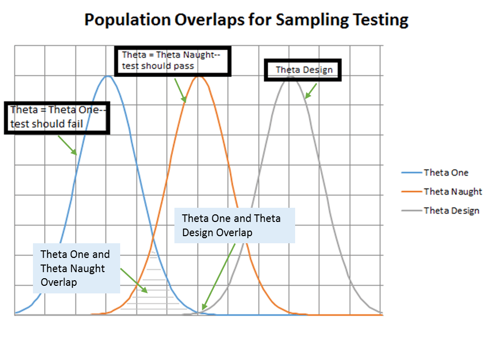
Figure 1. Overlap of Continuous Probability Curves
Electric Train Operational Test Example: An Independent Operational Test and Evaluation (IOT&E) event is scheduled for the electric trains. These are no longer toy trains but are instead the first operationally representative prototypes from an MDAP to develop new trains. Because of the cost and complexity of the system, only two test items are available for the IOT&E. The specified requirement is a 95% chance of completing the standard mission duration of 36 hours. The required value of Ɵ is desired.
We derive the Ɵ MTBCF requirement using:
Reliability at time t = R(t) = e-λt
Note that λ = failure rate = 1/MTBCF:
So, R(t) = e-t/MTBCF
Taking the natural log of both sides and re-arranging terms:
Ln R(t) = -t/MTBCF → MTBCF = – t / Ln R(t)
Using the specifications (95% chance of completing a 36 hour mission) we can determine the required MTBCF as:
MTBCF = – 36 / Ln (0.95) = – 36 / – 0.0513 = 702 hours
Now that we have our Ɵ (702 hours), it is necessary to design the required test. The first consideration is what is the minimum number of test hours required to demonstrate an MTBCF of 702 hours? The minimum test time can be determined from the “failure-free testing” one-sided lower limit at a significance level, α, of 0.1 (for a 90% one-sided LCL):
From “Reliability Statistics” by Robert A. Dovich, the equation for the failure free testing lower limit is:
MTBF ≥ – n * T / ln α
This equation can be re-arranged to:
MTBF * ln α ≥ – n * T
Noting that n * T is actually the total test time, we can calculate the minimum total test time required:
Minimum Total Test Time = – MTBCF * ln α = – 702 * ln 0.10 = 1616.4 hours
So, we should just put the two trains on test for 1616.4 total hours (or 808.2 hours each) and if there are no failures we will have demonstrated the required MTBCF has been achieved, right? Unfortunately, it isn’t this easy. The number of failures observed is a random variable based on the exponential distribution used in the reliability equation above. We can use this knowledge to predict the number of failures we expect to see in 1616.4 test hours if the population actually has a 702 hour MTBCF. A simple initial way to view this is:
What is the probability of seeing 0 failures in 1616.4 test hours given an achieved 702 hour MTBCF? We calculate that from the reliability equation:
R(t) = e-t/MTBCF = e-1616.4/702 = 0.100 or 10%
Which makes sense because we defined the test for 10% significance.
So, we could happily tell the random variable r that it will be zero and run our test for 1616.4 hours and 1 time in 10 it will oblige. The other 9 times it will take on a non-zero value and we will have “failed” our test. This “failure-free” test plan has a 90% Producer’s Risk (since we calculated it based on having the true state, Ɵ, be equal to the specified ƟD so the system should pass the test). In reality we will need to take into account our acceptable levels of risk to design an adequate test.
Risk in testing is related to the length of the test (more testing usually means lower risk) and the value of Ɵ compared to Ɵ1. The higher the ratio Ɵ/Ɵ1 the lower the test risk will be. This is shown in Figure 1 by the size of the areas where the Ɵ1 curve overlaps the Ɵ0 and ƟD curves. By designing the system to a higher reliability than required (i.e. ƟD > Ɵ1) we reduce the test risk but we incur higher development costs through implementation of reliability improvement techniques such as Highly Accelerated Life Testing (HALT), other Physics of Failure (PoF) approaches, and, less desirably, potentially increase system cost, complexity, size, and weight through incorporation of additional redundancy. Another way of reducing test risk would be through increasing test time which will reduce the width of the curves (as the results move closer to the true value of Ɵ) which decreases the overlap but increased testing involves higher costs and will add significant time to the development schedule (if testing cannot be accelerated through adding more test articles and/or running accelerated testing). It is usually impractical to increase IOT&E testing to allow for lower risk reliability evaluation.
Electric Train Operational Test Example, Part 2: Returning to the train example, we will assume that the maximum available test time for the IOT&E is 2000 hours. What is the minimum value of ƟD we should set given Producer’s Risk = Consumer’s Risk = 0.20?
We start the analysis by revisiting the requirements:
Ɵ0 ≥ 702 hours to give 95% RM
T = 2000 hours
Next, we set the risk related requirements through discussion and agreement with stakeholders:
α = β = 0.20
Ɵ1 = 342 hours (equates to RM ≈ 90%)
We then use established equations for the maximum number of failures allowed during time truncated testing to find the minimum value for ƟD:
ƟD ≥ 871 hours
Conclusion—Why Did We Look at this Example?
The takeaway here is that while the customer requirements could be met by a system with a 702 hour MTBCF, the limitations (time, cost, schedule, test item availability, etc.) of the IOT&E event required overdesigning the system MTBCF by 24% solely to reduce the risk of failing the test without adding significant operational utility. Increasing the MTBCF from 702 hours to 871 hours only improves RM from 95% to 96% while most likely significantly increasing system complexity, cost, and weight. This is not usually an effective design approach for DOD systems, since, for the most part, smaller, lighter, and faster is desired. Testing and reliability demonstration should strive to avoid forcing overdesigning a system simply to pass a test without tangible benefits to the customer. Understanding the meaning of test results including what risks are present due to the test design is the most important factor in evaluating reliability demonstrated during testing.
Final Thoughts
There is another approach to demonstrating that reliability is “good enough” without determining what the reliability “is” that can be very useful here. Sequential Testing, once a staple of DOD program development, is a method that enables a quick decision as to whether the reliability is more likely Ɵ1 (fail) or Ɵ0 (fail to reject—i.e. “pass”). This involves running the test until a statistical decision can be reached for either outcome. In cases where Ɵ is either much lower or much higher than Ɵ0 this approach can save a significant amount of test time but it will not always provide a high confidence estimate of the achieved reliability. Sequential Testing is the dominant approach in the commercial world due to its efficiency and is now beginning to return to the test plans for MDAPs which should improve the effectiveness of DT and OT in assessing reliability.
About the Author
Mr. Schmieder has 34 years of experience in Logistics and Reliability Engineering, working on multiple Defense and Commercial device development and evaluation programs. Currently he is a Modern Technologies Solutions Inc. (MTSi) Principal Engineer supporting a DOD program office. He has a Masters in Systems and Industrial Engineering from the University of Arizona, is an ASQ Certified Reliability Engineer and ASQ Certified Six Sigma Green Belt. In previous positions he has worked on telecommunications equipment and medical device development programs and spent nine years supporting OUSD(AT&L) Systems Engineering program oversight and policy development efforts. He was the technical lead for the development of the RAM-C Rationale Report Manual for DOD. He welcomes discussion and can best be reached by e-mail at grantsaz@yahoo.com.
List of Acronyms Used in This Article
Acronym Explanation
ASQ American Society for Quality
DACS Data and Analysis Center for Software
DOD Department of Defense
DT Development Test
FDSC Failure Definition and Scoring Criteria
FMEA Failure Modes and Effects Analysis
HALT Highly Accelerated Life Testing
IOT&E Independent Operational Test and Evaluation
LCL Lower Confidence Limit
MDAP Major Defense Acquisition Program
MTBCF Mean Time Between Critical Failure
MTBF Mean Time Between Failure
OT Operational Test
OUSD(AT&L) Office of the Under Secretary of Defense (Acquisition, Technology, and Logistics)
PoF Physics of Failure
References
- System Reliability Toolkit, 2005, Reliability Information Analysis Center (http://acqnotes.com/acqnote/careerfields/reliability-information-analysis-center)
and Data and Analysis Center for Software (DACS) (https://en.wikipedia.org/wiki/Data_%26_Analysis_Center_for_Software).
- Dovich, Robert A. Reliability Statistics. Milwaukee, Wisconsin USA: American Society for Quality (ASQ) Press, 1990. See https://www.amazon.com/Reliability-Statistics-H0601-Robert-Dovich/dp/0873890868/ref=sr_1_3?s=books&ie=UTF8&qid=1507133294&sr=1-3&keywords=Robert+A+Dovich.
- Dovich, Robert A. Quality Engineering Statistics. Milwaukee, Wisconsin USA: American Society for Quality (ASQ) Press, 1992.
- MIL-HDBK-108, Sampling Procedures and Tables for Life and Reliability Testing, 29 April 1960.
- Reliability, Availability, Maintainability, and Cost Rationale Report Manual, 2009, OUSD(AT&L).
- American Society for Quality. The Certified Reliability Engineer Handbook, 3rd Ed. (e-book). Milwaukee, Wisconsin USA: American Society for Quality (ASQ) Press, 2017 (see https://asq.org/quality-press/display-item?item=E1535).
- Burke, Sarah E. and Rachael T. Silvestrini. The Certified Quality Engineer Handbook (4th Ed.). Milwaukee, Wisconsin USA: American Society for Quality (ASQ) Press, 2017 (see https://asq.org/quality-press/display-item?item=H1518).
Article
Integrating Program Management and Systems Engineering
by
Dr. Ralph R. Young, Editor, SyEN
This month we provide a summary of Chapter 4 in Integrating Program Management and Systems Engineering (“The Book”), a collaboration of the International Council on Systems Engineering (INCOSE), the Project Management Institute (PMI), and the Consortium for Engineering Program Excellence (CEPE) at the Massachusetts (USA) Institute of Technology (MIT).
Chapter 4 of this new and profound book is titled “The Case for Integrating Program Management and Technical Management”. This is a critical issue for all systems engineers because the current approach of systems development and project/program management (PM) lacks integration of PM and systems engineering and is not sustainable.
As we understand, program management and systems engineering are different. The challenge is one in which the chief systems engineer is attempting to describe and define the optimal solution while at the same time the program manager is attempting to determine the necessary work components, develop the program implementation plan, and discern how to deliver benefits to stakeholders. Having one person fill both roles does not scale well in the complex systems environment that exists today. A starting point for improved integration of the two disciplines is a foundational understanding of both disciplines and the standards that inform the practice of the disciplines. Tension between the two disciplines has its roots in the specialized practices and standards that are highly role specific and often have different measures of success. Whereas the project manager (PM) manages for benefits delivery, the chief systems engineer (SE) is often concerned with optimizing the components. If these roles are not working together closely, the result is often contention and conflict.
A significant difference that exists between project/program management and systems engineering is the standards that are used by the two disciplines. PMI members developed The Standard for Program Management, now in its third edition, as a consensus-based standard, detailing the common practices of the profession, and building on internationally published practice and research. In 2007, PMI released the Program Management Professional (PgMP) credential to certify mastery of the knowledge and practice experience related to managing programs. PMI also offers the Project Management Professional (PMP) certification.
Unlike engineers whose detailed technical training and credentialing requirements forge a strong shared identity regardless of other differences, program managers may come into the profession from various backgrounds and paths. While there is movement toward formal degree programs in program management, today it is still much more likely that the PM will have developed skills based primarily from on-the-job experience.
The INCOSE United Kingdom (UK) chapter developed a Systems Engineering Competency Framework (“Z6”)[1] that describes the competencies that are required to conduct good systems engineering, consistent with International Standards Organization (ISO) 15288, EIA 632, and the INCOSE Systems Engineering Body of Knowledge and Systems Engineering Handbook. The Systems Engineering Competency Framework was adopted by INCOSE and reflects the organization’s position on systems engineering competencies. As we know, it takes a lot of education and training as well as years of experience to become a solid systems engineer. Unlike the program manager role, systems engineers share a common foundational knowledge associated with engineering and engineering management principles. Some systems engineers may have extensive exposure to their discipline without opportunities to develop broader management experience. This isolated professional development may contribute to unproductive tension with program managers.
The examples of differing standards and different education and training suggests a danger that representatives of the two disciplines may continually have a different view that sees possible solutions through their respective lenses. Isolated mindsets have occurred in many technical programs, and the result has been lack of cooperation and failure to achieve an integrated approach. Seeing different approaches and solutions can lead to unproductive tension. Each discipline often focuses on the solution from its own perspective without collaboration toward the optimal solution.
One of the dimensions that formed the research base for The Book was the level of unproductive tension that existed between the two disciplines. Survey respondents rated the degree to which unproductive tension between program managers and systems engineers existed in their organization. Among the factors rated by respondents, three key factors stood out as sources of unproductive tension: lack of integrated planning, authority not clearly defined, and conflicting practices for program management and systems engineering.
Program managers and chief systems engineers each have unique but intertwined roles to play in successful program outcomes. Viewed exclusively from their own professional identities, capabilities, and methods, the need to work together may not be apparent. They each have their own discipline-based measures of what problems have highest priority along with associated rewards. Sometimes, their respective roles are not well-defined and may even be in conflict with one another. The opportunities and rationales for them not working together closely are manifold, and the result can be unproductive tension, or worse.
Integration of roles entails a mindset change for individual employees and changes to processes and procedures for the organization. The latter may require a change to organizational culture, which comes with its own set of issues.
The research provided several case studies of excellent integration and program success. The key to success seems to be when the PM and the SE embrace the overall goal of improved technical program performance and each practitioner’s ability to continue to that goal. Further, each must find ways to apply specialized knowledge of their respective disciplines in a way that works to produce a sum greater than the parts (empowered teams). This requires a vision beyond the task at hand and can prove to be extremely difficult because it requires developing some new ways of looking at the challenges – a task that forces new patterns of thinking.
As the case studies in The Book show, the benefits of integration far outweigh the effort required to integrate the disciplines. The payoff can be large. But it is not necessary to move from minimal integration to full integration in one step. Change begins with the first step and is sustained by determining to press on with the next step even when the going gets rough.
Where have you seen successful integration of the disciplines of program management and systems engineering in your organization? Have you noted examples of unproductive tension? What do you think might be done at the project/program level and also for the organization to provide added integration and, thus, higher probability of program success?
INCOSE International Symposium (IS) 2018 – Washington DC, USA
Delivering Systems in the Age of Globalization
Saturday, July 7 – Thursday, July 12, 2018
Grand Hyatt Washington1
000 H Street NW
Washington, DC 20001USA
Tel.+1 202 582 1234

Call for submissions
The INCOSE International Symposium is the premier international forum for Systems Engineering. Participants network, share ideas, knowledge and practices, and learn more about the most recent innovations, trends, experiences and issues in Systems Engineering from world-class thought leaders.
Key Dates
| Submission deadline | 10th November 2017 |
| Notification of acceptance and referee comments | 16th February 2018 |
| Final Manuscript | 30th March 2018 |
Systems Engineer Day – November 24th, 2017
With the world becoming more and more digitized every day, there is a group of people that has rather suddenly become one of the most important groups of people in the world: systems engineers. Systems engineers make enormous contributions to the world as we know it every single day, allowing us to live the increasingly comfortable lives we are accustomed to, and neither our personal nor our professional lives would be the same without them. Systems engineers work on numerous complex projects: spacecraft design, computer chip design, robotics, software integration, and bridge building. The computer you’re using right now to read this article would not exist if it weren’t for systems engineers, nor would the plane you’re taking to go to your exotic holiday destination, and nor would the bridge you need to cross to get to work every day. And let’s not forget the International Space Station, one of the most impressive examples of what systems engineering can accomplish. Though systems engineering is a very young profession, there is no disputing that it is one of the most important ones in today’s world.
The History of Systems Engineer Day
The term systems engineering first appeared in Bell Telephone Laboratories in the 1940s. Today, 75 years later, systems engineering has been divided into many fields and sub-fields including cognitive systems engineering, industrial engineering, mechatronic engineering, reliability engineering, security engineering and software engineering, to name but a few.
Systems Engineer Day was created just recently by the folks at www.systemsengineerday.com as a way of saying thank you to the men and women who sit in front of computers for hours every day to make our lives better and easier.
How to Celebrate Systems Engineer Day
If you yourself are a systems engineer, today is your day, so make the most of it: maybe it’s high time you took a day off and looked at a real landscape instead of the Windows desktop ones. Relax your eyes, enjoy the fresh air, have a picnic! Or if you fancy a more social situation, why not get together with your other systems engineer buddies and just have some beers, hang out and laugh at jokes only you understand?
What Do Systems Engineers Need to Know About Cybersecurity?
The applications of systems engineering are extensive. Information security can be regarded as a specialty discipline, and cybersecurity an application of that specialty discipline. A recent summit concerning cybersecurity raised a number of key issues that are relevant to the practice of systems engineering. Foremost among them is that cybersecurity must be a priority for all of us.
The Washington Post (USA) sponsored its seventh annual Cybersecurity Summit (2017) on October 3rd, 2017. Government leaders, security experts, and security advocates gathered for a discussion of the top issues. Speakers addressed hacks, cybercrime, cyberspying as well as the latest developments in protecting consumer data and critical infrastructure. Speakers included Rob Joyce, White House Cybersecurity Coordinator; General Michael Hayden (Ret.), Former Director, Central Intelligence Agency and National Security Agency; Representative Will Hurd, Member, House Committee on Homeland Security and House Permanent Select Committee on Intelligence; Michelle Richardson, Center for Democracy and Technology’s Freedom, Security, and Technology Project; Richard Clark, Former White House Advisor; Christopher Furlow, President, Ridge Global; Marcy Wheeler, National Security Journalist; and Jeffrey Lush, U.S. Federal Chief Technology Officer, HP Enterprise (HPE).
Some of the interesting insights provided by the speakers included the following:
- It’s critical for all to operate in the international space. In particular, we should look to bilateral agreements with individual countries.
- Cyber (security) has many communities and jurisdictions. The current strategy is to optimize what we have.
- The Vulnerabilities Equities Process (VEP) (https://thecyberwire.com/events/cycon2016/the-vulnerabilities-equity-program-disputed-questions.html) is not well understood. A charter for the VEP is being finalized that will include criteria and participants.
- We need to emphasize the people component of technology.
- Theft of data is “honourable espionage” – all countries do it.
- Social media is the main way we communicate these days.
- The sophistication of cyber efforts is different today in scale, style, and approval at the highest level.
- We need to make encryption stronger.
- Companies must have a good cybersecurity risk profile. They must be willing to invest money. Currently, companies are spending 3-5% on cyber; they need to spend 8-12%. From the National perspective, there needs to be a penalty for making mistakes. Then, the business model will ensure that needed investments are made.
- Executives in companies, legislators, and the general public need to get up-to-speed concerning risk management of cybersecurity.
- Executives do not understand the value of the data they possess.
- There is a tendency in Government to underplay potentialities. We need to open views to the broader society.
- Regarding the “Internet of Things (IOT), today there are an estimated five billion devices; the projection is for 30 billion devices in 3-4 years. This vastly increases the number of devices being rushed to the market that do not address cyber concerns.
- We are getting many of the basics wrong, including passwords, two-factor identification, the number of data centers in existence, licensing of software, inventories of software on our systems, privacy, international harmonization, and the need to build trust, for examples.
- Technology has outpaced our abilities at the policy level.
- Systemic changes need to be sponsored by companies and governments.
Featured Organization
Defence Science and Technology Group
The Defence Science and Technology Group (abbreviated as DST Group or DST) is part of the Australian Department of Defence dedicated to providing science and technology support for Australia’s defence and national security needs. It is Australia’s second largest government-funded science organization after the CSIRO. The agency’s name was changed from Defence Science and Technology Organization (DSTO) to Defence Science and Technology Group on 1 July 2015.
To achieve its mission, DST provides scientific and technical support to current defence operations, investigates future technologies for defence and national security applications, advises on the purchase and smart use of defence equipment, develops new defence capabilities, and enhances existing systems by improving performance and safety and reducing the cost of owning defence assets.
The Chief Defence Scientist leads DST. The position is supported by an independent Advisory Board with representatives from defence, industry, academia and the science community. DST has an annual budget of approximately $440 million and employs over 2500 staff, predominantly scientists, engineers, IT specialists and technicians.
DST has establishments in all Australian states and the Australian Capital Territory with posted representatives in Washington, London and Tokyo. DST collaborates with science and technology organizations around the world to strengthen its technology base and works closely with Australian industry and universities to enhance defence capability. International engagement allows DST to explore potential technological opportunities at significantly less cost and provides access to overseas capabilities otherwise not available to the ADF. DST is a member of The Technical Cooperation Program (TTCP) with the United States, United Kingdom, Canada and New Zealand. It also has bilateral defence science agreements with USA, UK, France, Sweden, Netherlands, Norway and Singapore. In February 2012, DST was given the whole-of-government responsibility to co-ordinate research and development for Australia’s national security.
For more information on systems engineering related conferences and meetings, please proceed to our website.
Some Systems Engineering-Relevant Websites
Applied Systems Thinking
Michael Goodman and David Peter Stroh have over 50 years of experience with working with leaders in applying Systems Thinking and have created this site containing a wealth of information to help introduce Systems Thinking to people at all levels of the organisation. Resources and services are on offer that will help to develop technical skill and improve effectiveness when applying the principles of Systems Thinking and tools.
http://www.appliedsystemsthinking.com/testimonials.html
Systems Engineering Software
This site contains access to tools for modelling languages Chi 3 and CIF 3 and cross platform scripting language ToolDef 2. The tools were developed by the Systems Engineering group of the Mechanical Engineering Department at Eidhoven University of Technology.
http://update.se.wtb.tue.nl/documentation/
Systems Engineering Job Description Sample
This free system engineer job description sample template can assist recruiters in attracting innovative and experienced systems engineers to their company. Requirements, benefits and perks specific to the company should be added to this template before advertising for employment.
https://www.ziprecruiter.com/blog/systems-engineer-job-description-sample-template
CSEP Overview
Downloadable presentation containing an overview of the Systems Engineering Professional certification program by the International Council on Systems Engineering (INCOSE).
http://www.swe-sc.org/Seminar/CSEP_Overview-%20Heidel.pdf
Innoslate
A full lifecycle systems engineering tool that enables model-based diagrams, requirements management, lifecycle traceability, verification and validation, simulation and much more.
https://www.innoslate.com/systems-engineering/
INCOSE UK “Z Guides”
INCOSE UK has produced a series of accessible guides to aspects of systems engineering, each in the form of a one page, double sided, guide designed to be folded up into three panels giving a “Z” cross section, to be known as “Z-Guides”. The aim is to provide focused, accessible, information which can be presented to individuals who are not directly involved in systems engineering on a day to day basis.
https://incoseonline.org.uk/Program_Files/Publications/zGuides.aspx?CatID=Publications&SubCat=zGuides
Systems Engineering Publications
Collaboration Across Linked Disciplines: Skills and Roles for Integrating Systems Engineering and Program Management
by
Eric Rebentisch (MIT), Stephen Townsend (PMI), and E.C. Conforto (MIT Consortium for Engineering Program Excellence (CEPE), Sociotechnical Systems Research Center (SSRC)
Abstract
In new product development programs, systems engineers and program managers must often work together closely to define the product, the program structure and objectives, and allocate and define the focus of work effort. Poor communication and lack of integration between these two critical functions can often spell the difference between success and disappointment for the program and its stakeholders. Despite common and sometimes overlapping skills required for both disciplines, and their respective extensive practice and process models, effective integration and collaboration continues to elude many engineering efforts. Unfortunately, this failure of collaboration and integration negatively impacts program performance and outcomes. This study draws upon a large global survey of program managers and systems engineers to better understand the backgrounds, training, roles, and responsibilities of program managers and systems engineers. The analysis of the data identifies systems engineering and program management capabilities that are considered critical to program success, as well as those areas where both roles share key responsibilities. The implications of these findings for engineering students and for their engineering curricula will be discussed. For systems engineering students and future engineering leaders, having learned these principles and concepts may be critical to them as they prepare to enter a highly competitive workforce.
To better understand these issues and their impact on professionals in the project/program management and systems engineering fields, in the Fall of 2012 INCOSE and PMI established a joint working group to investigate the issues and challenges to developing closer working relationships between program management and systems engineering disciplines in organizations. One of the primary objectives of this alliance was to identify potential areas for improvement, from both a theoretical and a practical perspective.
Data were collected during the fall of 2012. An invitation to participate in the study was sent to approximately 3,000 members of the INCOSE System Engineering community of practice and to approximately 5,000 members of the PMI Program Management community of practice.
Conclusions
The analysis confirmed roles and skills for engineering program leaders (PMs and CSEs) that are consistent not only with traditional engineering education and training programs but also professional standards and certifications. This reinforces the notion that these roles are indeed part of functional disciplines based in specialized knowledge. While each of these domains has unique roles and skills, there are significant areas of overlapping or shared responsibility, particularly with respect to PMs. Both PMs and CSEs are viewed as jointly accountable for managing program and project risk, external supplier relations, quality management, and lifecycle planning. In each of those areas (e.g., managing program and project risk) there are unique perspectives and analyses that each function brings to the shared responsibility. Nevertheless, successful integration may not be so much in the accumulation of multiple analyses as in the way in which one analysis or perspective informs the other, and ultimately shapes the unified program-level approach. This suggests the ability to synthesize integrated solutions from multiple perspectives is an important engineering leadership skill. Whether through shared responsibilities or from the need to share knowledge derived from unique functional responsibilities, the respective functions need the ability to work together in an integrated fashion. The most important skills claimed by PMs include leadership and stakeholder management. Combined, these suggest the ability to bring together diverse interests to embrace a common objective and work collaboratively. The most important skills claimed by CSEs include system thinking and requirements management, which suggest an ability to link overarching objectives to detailed elements in a holistic integrated perspective. Both PMs and CSEs share communication as a key skill. An educational or professional development program may not necessarily need to develop all of these skills in its students, but it should nevertheless strive to develop an understanding and appreciation of the different roles that are required in an integrated program leadership team. Innovative engineering leadership education programs increasingly emphasize the introduction of more elements of lifecycle processes and operations for engineered systems, including interpersonal skills and leadership. Yet, they still may not address some of the organizational and relational elements highlighted by this study. Particularly, integration across functional and organizational boundaries appears to be an important element of engineering program success. Unproductive tension between the PM and SE disciplines results when integration of the functions is informal, ad hoc, or just ineffective. The roots of unproductive tension may ultimately lie with poorly-defined roles and relationships in the program and organization. As engineering efforts became more integrated, as relationships become more explicit and formally-defined, the unproductive tension in organizations is seen to decrease. This suggests that organizational or program design may play a significant role in shaping the effectiveness of engineering efforts. While engineering students may learn a good deal about product design during the course of their education, they may not be exposed as extensively concerning the design of organizations and the relationships they embody. It is recommended that these issues be considered for addition in future engineering leadership curricula.
Process Analyzer Systems Project Engineering and Management
by
Gary Nicols
Book Description (from the Automation.com web site):
This book includes specific recommendations for defining hardware and documentation deliverables, adhering to procurement policy, working with team members in other disciplines and in the supply chain, and communicating among project teams.
The Industries of the Future
by
Alec Ross
Book Description (from the Amazon web site):
Leading innovation expert Alec Ross explains what’s next for the world: the advances and stumbling blocks that will emerge in the next ten years, and how we can navigate them. While working as Senior Advisor for Innovation to the Secretary of State, he traveled to forty-one countries, exploring the latest advances coming out of every continent. From startup hubs in Kenya to R&D labs in South Korea, Ross has seen what the future holds.
In The Industries of the Future, Ross shows us what changes are coming in the next ten years, highlighting the best opportunities for progress and explaining why countries thrive or sputter. He examines the specific fields that will most shape our economic future, including robotics, cybersecurity, the commercialization of genomics, the next step for big data, and the coming impact of digital technology on money and markets.
In each of these realms, Ross addresses the toughest questions: How will we adapt to the changing nature of work? Is the prospect of cyberwar sparking the next arms race? How can the world’s rising nations hope to match Silicon Valley in creating their own innovation hotspots? And what can today’s parents do to prepare their children for tomorrow?
Ross blends storytelling and economic analysis to give a vivid and informed perspective on how sweeping global trends are affecting the ways we live. Incorporating the insights of leaders ranging from tech moguls to defense experts, The Industries of the Future takes the intimidating, complex topics that many of us know to be important and boils them down into clear, plainspoken language. This is an essential book for understanding how the world works—now and tomorrow—and a must-read for businesspeople in every sector, from every country.
The Certified Quality Engineer Handbook

by
Sarah E. Burke and Rachel T. Silvestrini
Book Description (from the Amazon web site):
This fourth edition is intended to provide the quality professional with a reference book aligned with the ASQ Certified Quality Engineer (CQE) Body of Knowledge (BoK). The book was not written solely as a study guide to pass the certification exam, but rather as a comprehensive guide to the field of quality engineering. Therefore, most of the chapters include material that goes well beyond the CQE exam requirements.
Based on the changes to the CQE BoK, as well as helpful feedback from colleagues and reviewers, this revised edition contains the following major changes:
- A new chapter on risk management
- An extensively updated glossary
- New and updated references
- A new layout
The editors included many new textbook and journal article references throughout the entire book. Within the discussion of continuous improvement methods, they added descriptions of and references to several case studies. These case studies, which include applications in the service industry, give the reader a broader context on how to apply many of the methods discussed in a real-life scenario. In particular, some of these case studies are related to quality in the service industry. Additionally, the editors updated discussions of and references to new technology important to the quality professional, such as Industry 4.0.
Configuration Management Best Practices
by
Bob Aiello and Leslie Sachs
Book Description (from the Amazon web site):
As IT systems have grown increasingly complex and mission-critical, effective configuration management (CM) has become critical to an organization’s success. Using CM best practices, IT professionals can systematically manage change, avoiding unexpected problems introduced by changes to hardware, software, or networks. Now, today’s best CM practices have been gathered in one indispensable resource showing you how to implement them throughout any agile or traditional development organization.
Configuration Management Best Practices is practical, easy to understand and apply, and fully reflects the day-to-day realities faced by practitioners. Bob Aiello and Leslie Sachs thoroughly address all six “pillars” of CM: source code management, build engineering, environment configuration, change control, release engineering, and deployment. They demonstrate how to implement CM in ways that support software and systems development, meet compliance rules such as SOX and SAS-70, anticipate emerging standards such as IEEE/ISO 12207, and integrate with modern frameworks such as ITIL, COBIT, and CMMI. Coverage includes:
- Using CM to meet business objectives, contractual requirements, and compliance rules
- Enhancing quality and productivity through lean processes and “just-in-time” process improvement
- Getting off to a good start in organizations without effective CM
- Implementing a Core CM Best Practices Framework that supports the entire development lifecycle
- Mastering the “people” side of CM: rightsizing processes, overcoming resistance, and understanding
workplace psychology - Architecting applications to take full advantage of CM best practices
- Establishing effective IT controls and compliance
- Managing tradeoffs and costs and avoiding expensive pitfalls
Configuration Management Best Practices is the essential resource for everyone concerned with CM: from CTOs and CIOs to development, QA, and project managers and software engineers to analysts, testers, and compliance professionals.
Systems Engineering Tools News
BigLever’s Gears Product Line Engineering Tool and Lifecycle Framework™
The characteristic that distinguishes the systems and software product line engineering (PLE) approach from the traditional product-centric approach is when an organization has a means of production that enables it to efficiently create a product line of similar systems from a consolidated set of soft assets such as requirements, designs, source code and test cases. The focus on that singular means of production rather than a focus on the multitude of products is what makes the BigLever Software Gears™ approach so unique.
The Gears PLE Lifecycle Framework provides a set of industry-standard PLE concepts and constructs that augment your existing tools, assets and processes across the entire lifecycle:
- A feature model that you use to express the feature diversity (optional and varying feature choices) among the products in your product line.
- A uniform variation point mechanism that is available directly within your tools and their associated assets, to manage feature-based variations in all stages of the engineering lifecycle.
- A product configurator you use to automatically assemble and configure your assets and their variation points – based on the feature selections you make in the feature model – producing all of the assets for each product in your product line.
Education and Academia
Stevens Institute of Technology Launches Industrial and Systems Engineering Undergraduate Program to Address Growing Need for Systems Engineers
There is a critical need for 21st Century technical leaders who can improve productivity and efficiency for enterprises in industry and government. Leaders in these enterprises are seeking engineers with analytical skills and a strong systems perspective. To help fill that need, Stevens Institute of Technology has launched a new undergraduate Industrial and Systems Engineering (ISE) program to prepare students with a broad-based engineering foundation, a systems thinking perspective and strong data analysis skills to improve existing systems and build new modern, efficient systems. The job outlook for industrial and systems engineers (ISEs) is expected to grow steadily over the next decade based on data from the Bureau of Labor Statistics. Typical roles Stevens ISE graduates are well-positioned to pursue after graduation include industrial engineer, systems engineer, systems integration engineer, quality engineer, project engineer, sales and marketing engineer, and more.
The Stevens ISE program emphasizes cross-disciplinary systems perspectives and complex data analysis in its core curriculum. The aim of the program is to teach students to think about the ways in which technology can help organizations accomplish goals through the application of data science to define engineering solutions. Another unique component of the Stevens ISE program is that students will have varied opportunities to interact with well-known systems engineering researchers at Stevens, which is home to state-of-the-art research centers: the Systems Engineering Research Center (SERC) and the Center for Complex Systems and Enterprises (CCSE). Through these centers, faculty, and undergraduate and graduate researchers, collaborate with interdisciplinary academic and industry partners to understand and address the increasing complexity of the world’s systems.
Standards and Guides
ASQ/ANSI/ISO/TR 9002:2016: Quality Management Systems — Guidelines for the Application of ISO 9001:2015
ISO/TS 9002:2016 provides guidance on the intent of the requirements in ISO 9001:2015, with examples of possible steps an organization can take to meet the requirements. It does not add to, subtract from, or in any way modify those requirements.
ISO/TS 9002:2016 does not prescribe mandatory approaches to implementation, or provide any preferred method of interpretation.
The ASQ Pocket Guide to Root Cause Analysis
All organizations experience unintended variation and its consequences. Such problems exist within a broad range of scope, persistence, and severity across different industries. Some problems cause minor nuisances, others leads to loss of customers or money, others yet can be a matter of life and death.
The purpose of this pocket guide is to provide you with easily accessible knowledge about the art of problem solving, with a specific focus on identifying and eliminating root causes of problems.
Root cause analysis is a skill that absolutely everybody should master, irrespective of which sector you work in, what educational background you have, and which position in the organization you hold. The content in this little pocket guide can contribute to disseminating this skill a little further in the world.
What is Cyber Security?
Cybersecurity is the body of technologies, processes, and practices designed to protect networks, computers, programs, and data from attack, damage, or unauthorized access. In a computing context, security includes both cybersecurity and physical security.
Ensuring cybersecurity requires coordinated efforts throughout an information system. Elements of cybersecurity include:
- Application security
- Information security
- Network security
- Disaster recovery / business continuity planning
- Operational security
- End-user education
One of the most problematic elements of cybersecurity is the quickly and constantly evolving nature of security risks. The traditional approach has been to focus most resources on the most crucial system components and protect against the biggest known threats, which necessitated leaving some less important system components undefended and some less dangerous risks not protected against. Such an approach is insufficient in the current environment. Adam Vincent, CTO-public sector at Layer 7 Technologies (a security services provider to federal agencies including Defense Department organizations), describes the problem:
“The threat is advancing quicker than we can keep up with it. The threat changes faster than our idea of the risk. It’s no longer possible to write a large white paper about the risk to a particular system. You would be rewriting the white paper constantly…”
To deal with the current environment, advisory organizations are promoting a more proactive and adaptive approach. The National Institute of Standards and Technology (NIST) for example, recently issued updated guidelines in its risk assessment framework that recommended a shift toward continuous monitoring and real-time assessments (https://www.nist.gov/cyberframework).
According to Forbes, the global cybersecurity market reached $75 billion for 2015 and is expected to hit $170 billion in 2020.
PPI Participation in the NZDIA Conference
We were pleased to have had more presence at the New Zealand Defence Industry Association (NZDIA) conference this year. Unfortunately, this conference tends to attract protesters who barricade entrances and make it very difficult for the conference to take place. The organisers this year masterminded contingency plans and managed to arrange access to the venue without too much disruption. This year we were pleased to see the conference showcased many different products and service offerings, fantastic and informative speakers as well as wonderful networking opportunities. It is always a pleasure being in New Zealand, the Kiwi’s are ever so welcoming and are happy to take the time to have a friendly chat. We are sure to further develop existing relationships as well as create many new ones from this exciting opportunity.
PPI Participation in the INCOSE South Africa Conference
The INCOSE South Africa Conference hosted its 13th Annual Conference over 11 – 13 Oct 2017. The conference attracted a mix of professionals from industry, government, and academia. The programme comprised of more than twenty peer reviewed papers, six tutorials and an impressive line-up of keynote speakers on various topics.
The conference also hosted the culmination of the GYSEOY (Greatest Young Systems Engineer of the Year) challenge as well as the WiSEMOY (Wisest Systems Engineering Mentor of the Year) Challenge.
There was also an opportunity for engineers attending the conference to start their journey in becoming certified as systems engineering professionals (SEPs) through INCOSE’s certification programme by taking the free INCOSE SEP knowledge exam based on the INCOSE handbook.
The INCOSE SA MBSE Working Group was officially launched at the conference as well.
More information on the conference can be viewed here.
Newest Addition to the List of INCOSE Systems Engineering Professionals
We are proud to announce that CTI’s Chinese Professional Development Manager, Victoria Huang has taken the INCOSE knowledge examination and has passed! Victoria will become the newest member of our team to become certified as a systems engineering professional! Congratulations Victoria.
Upcoming PPI and CTI Participation in Professional Conferences
PPI will be participating in the following upcoming events.
INCOSE UK, Annual Systems Engineering Conference (ASEC) 2017
(Exhibiting)
21 – 22 November 2017
Warwick, UK
12 – 13 December 2017
INCOSE San Diego Mini-Conference
2 December 2017
San Diego, California, USA
20 – 23 January 2018
Jacksonville, Florida, USA
7 – 12 July 2018
Washington, DC, USA
PPI and CTI Events
Systems Engineering 5-Day Courses
Upcoming locations include:
- Eindhoven, the Netherlands
- Las Vegas, NV, United Stated of America
- São José dos Campos, Brazil
Requirements Analysis and Specification Writing 5-Day Courses
Upcoming locations include:
- Las Vegas, NV, United States of America
- Amsterdam, the Netherlands
- Pretoria, South Africa
Systems Engineering Management 5-Day Courses
Upcoming locations include:
- Las Vegas, NV, United States of America
- Stellenbosch, South Africa
- Amsterdam, the Netherlands
Requirements, OCD and CONOPS in Military Capability Development 5-Day Courses
Upcoming locations include:
- Amsterdam, the Netherlands
- Ankara, Turkey
- São José dos Campos, Brazil
Architectural Design 5-Day Course
Upcoming locations include:
- London, United Kingdom
- Pretoria, South Africa
- Stellenbosch, South Africa
Software Engineering 5-Day CoursesUpcoming locations include:
- Pretoria, South Africa
- London, United Kingdom
- Las Vegas, NV, United States of America
Human Systems Integration Public 5-Day Courses
Upcoming locations include:
- Sydney, Australia
- Melbourne, Australia
CSEP Preparation 5-Day Courses (Presented by Certification Training International, a PPI company)
Upcoming locations include:
- Madrid, Spain
- Pretoria, South Africa
- Laurel, MD, United States of America
Kind regards from the SyEN team:
Robert Halligan, Editor-in-Chief, email: rhalligan@ppi-int.com
Dr. Ralph Young, Editor, email: ryoung@ppi-int.com
Suja Joseph-Malherbe, Managing Editor, email: smalherbe@ppi-int.com
Project Performance International
2 Parkgate Drive, Ringwood North, Vic 3134 Australia Tel: +61 3 9876 7345 Fax: +61 3 9876 2664
Tel Brasil: +55 11 3958 8064
Tel UK: +44 20 3608 6754
Tel USA: +1 888 772 5174
Web: www.ppi-int.com
Email: contact@ppi-int.com
Copyright 2012-2017 Project Performance (Australia) Pty Ltd, trading as Project Performance International.
Tell us what you think of SyEN. Email us at syen@ppi-int.info.