In This Edition
Quotations to Open On
Read More…
Feature Article
- Knowledge Management for Capability Engineering, by Sergey Tozik
Read More…
Article
- The Missing Link – Risk Identification, by David Hall and Laurie Wiggins
- What a High Performing Team Looks Like and How to Create One
- Integrating Program Management and Systems Engineering, by Ralph Young
Read More…
- INCOSE 2017 International Symposium Keynotes
- INCOSE Call for Nominations for Pioneer, Founder and Outstanding Service Awards
- The SDL Forum Returns
- National Renewable Energy Laboratory (NREL) Provides Systems Engineering News
- When Aerospace Met Oil & Gas at the INCOSE Texas Gulf Coast Systems Engineering Conference
- Stevens Professor Receives NSF Grant for Collective Design in Systems Engineering
- United States Department of Defense Announces Recipients of Value Engineering Achievement Awards
Read More…
Featured Organizations
- National Defense Industrial Association (NDIA) Systems Engineering Division
- The Design Society
- INCOSE Complex Systems Working Group
Read More…
Conferences and Meetings
Read More…
Some Systems Engineering-Relevant Websites
Read More…
Systems Engineering Publications
- Engineering a Safer World
- Flexibility in Engineering Design
- Applied Minds: How Engineers Think
- Systems Thinking for Social Change: A Practical Guide to Solving Complex Problems, Avoiding Unintended Consequences, and Achieving Lasting Results
- Communicate Like a Leader: Connecting Strategically to Coach, Inspire, and Get Things Done
Read More…
Systems Engineering Tools News
- Cradle
Read More…
Education and Academia
- Engineering Education Needs a ‘Major Shake up’
Read More…
Standards and Guides
- INCOSE Initiative to Establish ISO Standards for Feature-Based Product Line Engineering
- ISO/IEC/IEEE 21839 – Systems of Systems Considerations in Life Cycle Stages of a System
- ISO/IEC 90003 Software Engineering — Guidelines for the Application of ISO 9001:2015 to Computer Software
- ISO/IEC 15026-4 Systems and Software Engineering — Systems and Software assurance — Part 4: Assurance in the life cycle
- ISO/IEC/IEEE DIS 24748-2 Systems and Software Engineering — Life Cycle Management — Part 2: Guidelines to the Application of ISO/IEC/IEEE 15288
- ISO/IEC/IEEE 16085 Systems and Software Engineering — Life Cycle Processes — Risk Management
- ISO/IEC/IEEE 42010 Systems and Software Engineering — Architecture Description
- ISO/IEC/IEEE 42030 Systems and Software Engineering — Architecture Evaluation
Read More…
A Definition to Close On
Read More…
PPI and CTI News
Read More…
Upcoming PPI and CTI Participation in Professional Conferences
PPI and CTI Events
“It is what we make out of what we have, not what we are given, that separates one person from another.”
Nelson Mandela
“If we want to solve problems effectively…we must keep in mind not only many features but also the influences among them. Complexity is the label we will give to the existence of many interdependent variables in a given system. The more variables and the greater their interdependence, the greater the system’s complexity. Great complexity places high demands on a planner’s capacity to gather information, integrate findings, and design effective actions. The links between the variables oblige us to attend to a great many features simultaneously, and that, concomitantly, makes it impossible for us to undertake only one action in a complex system.
A system of variables is “interrelated” if an action that affects or meant to affect one part of the system will also affect other parts of it. Interrelatedness guarantees that an action aimed at one variable will have side effects and long-term repercussions. A large number of variables will make it easy to overlook them.
We might think of complexity as an objective attribute of systems. We might even think we could assign a numerical value to it, making it, for instance, the product of the number of features times the number of interrelationships. If a system had ten variables and five links between them, then its “complexity quotient”, measured in this way would be fifty. If there are no links, its complexity quotient would be zero. Such attempts to measure the complexity of a system have in fact been made.
Complexity is not an objective factor but a subjective one. Supersignals reduce complexity, collapsing a number of features into one. Consequently, complexity must be understood in terms of a specific individual and his or her supply of supersignals. We learn supersignals from experience, and our supply can differ greatly from another individual’s. Therefore there can be no objective measure of complexity.”
Dietrich Dörner, The Logic of Failure: Recognizing and Avoiding Error in Complex Situations
“Successful projects are usually conducted with clear objectives, by competent people, in a supportive environment, using effective processes based on sound principles.”
Robert John Halligan
Knowledge Management for Capability Engineering
by
Sergey Tozik
Science of Integration
Email: stozik@gmail.com
Version 1.0 September 1, 2017
Abstract
In the context of technology acquisition and utilization, the customer representatives become “by default” Capability Engineers expected to guide the evolution of their organizations’ technological infrastructure, as a basis for new or improved capabilities.
The Capability Engineers must counteract the Knowledge Waterfall phenomenon of not getting enough information from technology vendors or development contractors, while being expected to supply the contractors with requirements and other information about systems’ intended use and environment. As a coping mechanism, the Capability Engineers frequently rely on System Storytelling to integrate multiple sources of information into a coherent picture of both acquired systems and their fit into organizational processes. “Systems storytelling” is an informal process concerning the common method of integrating diverse sources of information into a coherent understanding.
This article presents four-stage Knowledge Factory Methodology as a more effective and efficient way for knowledge management during systems transformation into operational capabilities. The Object-Process Network modelling approach based on ISO/PAS 19450 Object-Process Methodology provides a common language for both development and operations, promising to become a versatile tool for the modelling of organizational situations and their diverse change processes.
Copyright © 2017 by Sergey Tozik. All rights reserved.
Introduction
Each engineered artifact must eventually pass from its producer to the actual users. In the mainstream context of contract-based systems development, the INCOSE Systems Engineering Handbook conceptualizes this process as the Transfer, preceded by the supplier-side Integration and Verification and followed by the customer-side Validation (Walden, Roedler, Forsberg, Hamelin, & Shortell, 2015). The Transfer process involves both integration of the artifacts into their intended environment and transfer of the responsibility from the supplier to the customer.
As the supplier’s accountability is contractually limited by the project scope, the customer is ultimately responsible for artifact’s utility to its users. The customer essentially becomes the “by-default integrator” of the resultant system-of-subsystems (including technology elements), mediating between the developers and the users (Cowper, Emes, & Smith, 2005). Technology-in-use is very different from the artifacts it utilizes (Orlikowski, 2000), and the deployed artifacts become surrounded by a “scar tissue” of changed practices and systems. Technology deployment requires a kind of “post-deployment therapy” that is most effective if all parties collaborate in mutual learning to utilize the technology and enhance operational capabilities (Edmondson, Bohmer, & Pisana, 2001).
Capability Engineers – Integrators and Coordinators
Many organizations employ in-house engineers to handle the acquisition and deployment of technology in their organizations – clinical engineers in health-care, acquisition officers in defense, technology integrators in education, and corporate IT professionals.
Customer-side engineers face similar challenges of acting as the “by-default integrators” (Cowper et al., 2005) of the acquired systems and are actually expected to lead the evolution of the interconnected systems behind their organization’s capabilities. It is appropriate to suggest the existence of “Capability Engineers” (Kemp & Mollett, 2011) as a kind of internal system-of-subsystems engineers in need for distinct tools and methodologies.
During systems deployment, Capability Engineers effectively become the center of a web connecting developers and users, as they both represent the external Development to the internal Operations and act as customers-on-site in the development teams (Millerand & Baker, 2010). For the contractors, capability engineers assume Systems Engineering roles (Sheard, 2013) of Requirement Owners, Customer Interface and Logistics & Operations (Tozik, 2015). In their own organization, capability engineers act as fully-fledged system-of-subsystems engineers – they still perform the roles of Requirement Owners, Customer Interface, Logistics & Operations, but also the roles of Coordinators and Integrators, Verification and Validation Engineers, Technical Managers, and Information Managers.
Capability Engineers are heavily involved in problem-solving and troubleshooting, consistent with their primary roles as Coordinators[1] and Integrators[2] and insufficient investment in the System Designer and System Analyst roles. They act as “knowledge brokers” between the external contractors and the internal stakeholders, providing the contractors with information about their organization and their own superiors with project status updates. Capability Engineers’ engagement is intensified by problem discovery and usually focused on problem solving, especially at the interfaces between new systems and in-service systems (Tozik, 2015).
Knowledge Waterfall
As different systems are developed and deployed independently into the existing ecosystem of in-service systems and infrastructure, assimilation of the new technology becomes an ongoing process of system-of-subsystems change (Kemp, 2010; Ven, Talik, & Hulse, 2012).
Capability Engineers are intimately familiar with System-of-Subsystems Debugging. The System-of-Subsystems Debugging is different from Systems Debugging, as there may be several system deployment projects running concurrently, affecting multiple capabilities in unexpected ways. Successful debugging requires a deep understanding of the systems being debugged (Agans, 2006), but the complexity of the organizational ecosystem makes it difficult to produce, preserve, disseminate, and utilize this knowledge.
System development contractors expect their customers to analyze and understand their organization’s ecosystem, define the acquired systems’ role, and communicate this understanding in the form of contractually binding customer requirements. The quality of the knowledge flowing from the customer to the contractor, either as requirement quality or user involvement, has been identified for decades by the CHAOS Reports as the principal driver of a project’s success or failure (Johnson, Crear, Vianna, Mulder, & Lynch, 2015).
In the opposite direction, the knowledge flow from the contractors to the customers is severely limited. Unless contractually bound to provide documentation, training, and support services, the contractors are reluctant to educate the customers. The users are expected to adapt to new systems without sufficient knowledge of the systems’ peculiarities resulting from design and implementation choices made by the contractor.
Even in the case of in-house development, the developers and technology specialists almost never volunteer their knowledge, mostly due to the inherent difficulty of “dumbing down” the design and implementation specifics. My investigation of system-of-subsystems debugging suggests an almost unidirectional knowledge flow from the users to system-of-systems integrators, to single system integrators, to application software developers, to IT infrastructure teams, to the specific technology vendor and specialists.
Since knowledge streams down the system hierarchy freely but requires “pumping up” in the opposite direction, the knowledge flow pattern resembles a “knowledge waterfall“.
Systems Storytelling
When confronted with the challenge of integrating new systems into their organization’s ecosystem, Capability Engineers are required to utilize knowledge about both the new systems and the target ecosystem. Testing and debugging become the central activity, as the engineers accept the systems from their developers and conduct user testing on the deployed systems.
Test preparation integrates knowledge from diverse sources – formal documents, conversations with users, developers, systems engineers, even rumors – as the Capability Engineers build their understanding of the systems under test. Formal project documentation is interpreted in discussions with both users and developers. Access to actual users is especially valuable, as well as access to high-level design knowledge (architecture, requirement, operational procedures) and persons with the broadest system-level view.
The main test of Capability Engineers’ knowledge is their ability “to tell the system’s story” – describe how the system works without referring to the documentation, both to users and engineers. The need to learn arises when the engineers discover gaps in the mental models behind the “systems storytelling” or when a lack of knowledge impedes production of the required results. Because of this prolonged learning, the Capability Engineers retain extensive implicit knowledge, but rarely produce any explicit documentation, so their experience is lost when they leave.
The “Knowledge Waterfall” requires Capability Engineers to deal with vast amounts of information acquired from multiple and uncoordinated sources. When the “Knowledge Waterfall” combines with informal “Systems Storytelling” to produce a rather inefficient knowledge production and management process, the Capability Engineers will surely benefit from a more efficient knowledge processing methodology tailored to their needs – the “Knowledge Factory”.
Knowledge Factory Methodology
The factory metaphor implies the processing of raw material into finished products, through a series of processing stages. The Knowledge Factory Methodology is a four-step processing cycle:
- Mining – the Capability Engineers mine raw knowledge from (1) available documentation from both their organization and system development contractors, (2) operating experience gained from working with the actual technology users, (3) technical experience by collaborating with the contractors on the development of new systems, and (4) experimental data obtained from testing system prototypes both in the laboratory and in the operating environment. The “systems storytelling” takes place at this stage. The search for raw knowledge is guided by questions generated throughout the entire learning process.
- Coding – the Capability Engineers code the “systems stories” in a common repository, preferably translating into a common language. No analytic processing is intended at this stage, and the knowledge coding is rather mechanical and straightforward.
- Engineering – the Capability Engineers analyze and synthesize information coded in the repository to identify gaps in their knowledge. This is the appropriate stage to apply all available analytic methods and tools. This stage also generates reports and other documentation expected from the Capability Engineers.
- Guiding – the Capability Engineers guide the next round of raw knowledge mining to fill the knowledge gaps identified earlier. The questions must match the information sources to be answered effectively – users are different from developers and experimentation is different from document acquisition.
Thinking in Patterns of Action
As capability integrators, Capability Engineers must counteract “the folly of designing artifacts, while hoping for patterns of action” (Pentland & Feldman, 2008). Organizations work with processes (missions, services, tasks) while acquiring artifacts (equipment, hardware, software, systems). An effective coding scheme must unify both viewpoints in a single model.
At the most basic level, organizations react to or control continuously evolving dynamic situations. Taking snapshots of a situation at moment A and at later moment B allows us to represent the situation change as a process starting at moment A and terminating at moment B. Recurring and perceivable processes (or “patterns of action”) are conceptualized separately as “routines” in Organization Science (Pentland & Feldman, 2005) and “behaviors” in Systems Engineering (Goel, Rugaber, & Vattam, 2009), giving different names to similar concepts.
Designing and implementing predictable and reliable patterns of action suitable to be activated in appropriate situations form the basis for both management and systems engineering. Managers and Systems Engineers alike refer to reliable patterns as organizational capabilities, employee competencies or machine functions.
Multipurpose Device of Object-Process Network
In recent years, we developed the Object-Process Network as a tool to assist Capability Engineers in their diverse tasks. Object-Process Network tool facilitates:
- Operational and design knowledge capture in a single model;
- Knowledge gaps identification and generation of questions guiding further learning;
- Test case generation from paths through the network; and
- Change impact analysis.
The Object-Process Methodology (OPM) (Dori, 2002), standardized as ISO/PAS 19450[3], provides a simple ontology of Things (Objects and Processes) and the relationships between them, presented in a dual visual and textual notation system. Conceptually, situation snapshots are Objects (something that exists), so the OPM is suitable to serve as a modelling language for Capability Engineering. Real-life situation snapshots and processes must be abstracted to be represented in a model, and Capability Engineers must exercise care with abstracting away the complexity. Mathematically, the Object-Process Network is a bi-partite graph linking two types of nodes – situation snapshots represented as OPM Objects and changes from snapshot to snapshot represented as OPM Processes.
Both situation snapshots and processes can be represented at different resolution levels. Situation snapshot resolution levels are purely spatial. The processes have duration, so they may be resolved in both space (linking situation snapshots at different resolution levels) and time (introducing intermediate situation snapshots).
As the Object-Process Network represents imperfect knowledge, its flaws generate learning opportunities. When coding raw information from diverse sources, Capability Engineers can classify many items as representing either situation snapshots or processes. For example, as each process representation must specify the initial and final situation snapshot, a missing snapshot identifies a knowledge gap, generates questions and guides further raw knowledge mining. A situation snapshot without associated generating process or without follow-up process identifies a knowledge gap as well.
The Object-Process Network assists in test generation as each path through the network represents a possible test case, automatically generating coverage metrics from a percentage of paths covered by a test suite.
Summary and Conclusions
This article reflects work in progress, a journey to develop methodologies and tools for Capability Engineers as internal systems engineers working in diverse domains – for example, clinical engineers in healthcare, technology integrators in education, or acquisition officers in defense. Such professionals are responsible for acquiring technological systems for their organizations, and they become “by-default integrators” of the systems-of-subsystems behind their organizations’ capabilities.
As mediators between systems development and organizational operations, they must acquire extensive knowledge of both their organizational processes and the technological systems, in a very short time.
They are expected to supply requirements and other information to systems development contractors, but get very limited information in return, so they must counteract the resulting Knowledge Waterfall phenomenon. The common method of integrating diverse sources of information into a coherent understanding is an informal process of “systems storytelling”.
Implementing a cycle of knowledge mining, coding, engineering, and guiding the next mining round allows the Capability Engineers to parse their learning into distinct activities. This four-stage Knowledge Factory Methodology becomes more efficient when supported by the modelling approach of an Object-Process Network based on the Object-Process Methodology notation. The Object-Process Network is a bi-partite graph linking situation snapshots by processes of propagating from one situation to another.
The Object-Process Network is constructed incrementally, reflecting the evolving reverse-engineering-like learning process. It allows concurrent and coordinated knowledge integration, impact analysis and test case generation.
List of Acronyms Used in this Paper
Acronym Explanation
OPM Object-Process Methodology
References
Agans, D. J. (2006). Debugging: the 9 indispensable rules for finding even the most elusive software and hardware problems. AMACOM.
Cowper, D., Emes, M., & Smith, A. (2005). 9.2.1 “….is he in heaven or is he in hell that illusive Systems Integrator?” – Who’s Looking After Your Systems Integration? INCOSE International Symposium, 15(1), 1313–1323. DOI: 10.1002/j.2334-5837.2005.tb00751.x.
Dori, D. (2002). Object-Process Methodology: A Holistic Systems Paradigm. DOI: 10.1007/978-3-642-56209-9.
Edmondson, A. C., Bohmer, R. M., & Pisana, G. P. (2001). Disrupted routines: Team learning and new technology implementation in hospitals. Adm Sci Q, 46(4), 685–716. http://doi.org/10.2307/3094828.
Goel, A. K., Rugaber, S., & Vattam, S. (2009). Structure, behavior, and function of complex systems: The structure, behavior, and function modeling language. Artificial Intelligence for Engineering Design, Analysis and Manufacturing, 23(1), 23. http://doi.org/10.1017/S0890060409000080.
Johnson, J., Crear, J., Vianna, L., Mulder, T., & Lynch, J. (2015). CHAOS Report 2015. Retrieved from http://www.laboratorioti.com/2016/05/16/informe-del-caos-2015-chaos-report-2015-bien-mal-fueron-los-proyectos-ano-2015/.
Kemp, D. (2010). 3.4.1 So what is “in service systems engineering”? INCOSE International Symposium, 20(1), 386–399. DOI: 10.1002/j.2334-5837.2010.tb01077.x.
Kemp, D., & Mollett, J. (2011). Would the real systems engineer please stand up? INCOSE International Symposium, Volume 21, Issue 1, Version of Record online: 4 NOV 2014.
Millerand, F., & Baker, K. S. (2010). Who are the users? Who are the developers? Webs of users and developers in the development process of a technical standard. Information Systems Journal, 20(2), 137–161. DOI: 10.1111/j.1365-2575.2009.00338.x.
Orlikowski, W. (2000). Using Technology and Constituting Structures: A Practice Lens for Studying Technology in Organizations. Organization Science, 11(4), 404–428. http://doi.org/10.1287/orsc.11.4.404.14600.
Pentland, B. T., & Feldman, M. S. (2005). Organizational routines as a unit of analysis. Industrial and Corporate Change, 14(5), 793–815. http://doi.org/10.1093/icc/dth070.
Pentland, B. T., & Feldman, M. S. (2008). Designing routines: On the folly of designing artifacts, while hoping for patterns of action. Information and Organization, 18(4), 235–250. DOI: 10.1016/j.infoandorg.2008.08.001.
Sheard, S. A. (2013). 5.2.1 Systems Engineering Complexity in Context. INCOSE International Symposium, 23(1). DOI: 10.1002/j.2334-5837.2013.tb03077.x.
Tozik, S. (2015). Engineering Component of IAF Project Officer Activities (in Hebrew). In Eighth Israeli National Conference in Systems Engineering.
Ven, M. Van De, Talik, J., & Hulse, J. (2012). An Introduction to Applying Systems Engineering to In-Service Systems. INCOSE International Symposium, 22(1), 879–894. DOI: 10.1002/j.2334-5837.2012.tb01377.x.
Walden, D., Roedler, G., Forsberg, K., Hamelin, D., & Shortell, T. (2015). Systems Engineering Handbook: A Guide for System Life Cycle Processes and Activities (Fourth Ed). (D. Walden, G. Roedler, K. Forsberg, D. Hamelin, & T. Shortell, Eds.). Wiley.
Ed. note: PPI provides a popular 5-day intensive course on capability development, the most recent delivery being in Amsterdam NL this month. The course leads participants in mainly workshop format through the development of a submarine search and rescue capability solution, with realistic examples of all major capability development artifacts: capability system description of intended use (OCD), capability system requirements specification (SyRS), capability system value model, capability system operational solution description (CONOPS), and the following artifacts related to a technology item forming a part of the capability solution: technology item description of intended use (OCD), technology item system requirements specification (SyRS), technology item verification requirements specification (VRS), technology item system effectiveness model, and a requirements specification for related operator training (SOW).
The Missing Link – Risk Identification
by
David Hall and Laurie Wiggins
Hall Associates and Sysenex, Incorporated
Version 1.0 September 10, 2017
Abstract
All risk management standards, guides, and process descriptions note that risk identification is a key component of an effective risk management framework. Further, an effective risk identification process should identify all types of risks from all sources across the entire scope of the program/enterprise activities. However, no document or solution provides sufficient guidance for identifying a risk management baseline. Further, risk identification as it is practiced today is a subjective, ad hoc, non-comprehensive, and non-repeatable process resulting in continuing failures and overruns in all types of product and service development and modification programs.
This article summarizes an improved approach to risk identification that fills this serious void. An analysis of over 500 programs, called the Risk Identification Analysis, its conclusions, and the tool developed on the basis of the analysis, Program Risk ID, are discussed.
Web site: http://www.programriskid.com/
Email: dave.hall@hallassociateshsval.com, wiggins@sysenex.com
Copyright © 2017 by David Hall and Laurie Wiggins. All rights reserved.
The Risk Identification Analysis and Its Conclusions
A fundamental question prompted undertaking the Risk Identification Analysis: “Why is risk management the only Systems Engineering (SE) process that does not require a baseline to be developed?” All other SE processes – configuration management, requirements management, design, architecture, and on – require that a baseline be developed for each program as one of the first steps after a program is established. This requirement does not exist for risk management. Risk management (RM) standards and guidelines [1, 2, 3, 4, 5, 6, 7, 8, 9, 10, and 11] do indicate that risk identification is an important step in the RM process, but they do not require that a risk baseline be developed. We define risk to be expected loss due to potential problems that can affect program cost, schedule, and/or performance. The term “program” also includes projects, activities, and operations.
There is a widespread belief that each program has a unique set of risks. This is false, based on the results of our Risk Identification Analysis (herein referred to as “the Analysis”). It has been determined that every program inherently has the same risks as every other one. It is the specifics of the risks that vary. For example, “Technology Risk” will change from program to program, depending on what technology one uses or what skills the involved people possess or require. These change as do the assessments and the impact(s), depending upon the specific program. But the overall baseline of technical, enterprise, operational, management, organizational, and external risks that should be considered remains the same. There are no unknown unknowns or Black Swans [12], only unconsidered risks. All risk management standards and guides fail in this regard: they do not require that all risk management processes/programs use the same basic set of risks for identification, thus creating a risk baseline for each program.
The risk management process has been fairly well standardized over the past 50 years – most risk management standards, handbooks, and guidebooks (references as noted above) use the same basic process steps, although using different names. A closer examination of the definitions shows that the steps are essentially the same – Planning, Identifying, Assessing, Prioritizing, Controlling, and Monitoring. When examining each of the steps, however, one finds that Identification (establishing a risk baseline) is essentially ignored except to state that it must be done. Risk Identification is defined as:
“…discovering, defining, describing, documenting, and communicating risks before they become problems and adversely affect a project. Accurate and complete risk identification is vital for effective risk management. In order to manage risks effectively, they must first be identified. The important aspect of risk identification is to capture as many risks as possible (author italics). During the risk identification process, all possible risks should be submitted. Not all risks will be acted upon. Once more details are known about each risk, the decision will be made by the project members as to the handling of each risk. There are various techniques that can be used for risk identification. Useful techniques include brainstorming methods as well as systematic inspections and process analysis. Regardless of the technique used, it is essential to include key functional area personnel to ensure no risks go undiscovered.” [13] (Italics provided by the author).
Common Historical Risks. The process steps for risk management, with the exception of risk identification, are outlined and defined. The lack of consideration in establishing a risk baseline is because of the mistaken belief that each program is unique and therefore its risks must also be unique. The Risk Identification Analysis has shown that this belief is wrong. As programs were analyzed, it became clear that the same risks kept occurring, over and over again. A set of common risks emerged. Thus there are a set of inherent risks that are applicable to any program and should be considered in developing a program risk baseline. These common risks provide a comprehensive method that can be used to develop a risk management baseline for all programs – based on this analysis of historical data.
The Analysis was conducted over 15 years by examining over 500 programs. Information from direct experience was utilized on over 70 programs; the others were researched using U.S Government Accountability Office (GAO) project reports concerning U.S. Department of Defense (DoD) projects, and anecdotal evidence gained from teaching risk management to approximately 3,500 people, including train the trainer sessions provided for National Aeronautics and Space Administration (NASA) Goddard personnel. Participants from these training programs shared confidential data during subsequent discussions that was not documented in papers or GAO reports. Programs (a blanket term that covers programs, projects, activities, and operations) include those in the commercial and governments sectors, as well as those from numerous domains. Aerospace programs include those from all branches of the DoD and NASA. IT programs covered both hardware and software. Energy and utility programs including facility construction were included.
Risk Weighting. As the risks were identified, it became apparent that some risks occurred more frequently than others. Also, when the risks occurred, some risks had a more detrimental effect on programs than others. In order to accurately gauge the effect of a given risk on a program, each risk needed to be weighted relative to the others. Once the risks were identified, the analytical hierarchy approach was used to perform the risk weighting.
Risk Levels. Once the inherent risks are identified, how would one determine the status of the risk? Consider management experience, for example. How does one determine whether this risk has been addressed properly or not? If no standard is provided, the risk status is subjective, completely up to a given individual. In order to reduce subjectivity, risk levels were defined for each risk to define its current status in the solution space for that risk. These risk level statements are based on historical data for numerous programs and incorporate areas such as the maturity of the process, the level of the design, the build level of the hardware, etc., for each risk. An example of a set of risk level statements is as follows:
Generic Risk: Requirements Definition
- Level 5 – System and user requirements are not defined, forcing the developer to make assumptions. There is no potential for definition of requirements for the long term.
- Level 4 – System and user requirements are not defined, forcing the developer to make assumptions. Assumptions are informally agreed to by the stakeholders or users. There is no potential for definition of requirements for the long term.
- Level 3 – System and user requirements are not defined, forcing the developer to make assumptions. Assumptions are informally agreed to by the stakeholders or users. Potential for definition of requirements in the short term exists.
- Level 2 – System and user requirements are partially defined: the remainder are to be defined in the short term and formally agreed to by all stakeholders.
- Level 1 – System and user requirements are fully defined and formally agreed to by all stakeholders.
- N/A – This risk is not applicable to the program being analyzed.
The risk levels provide the means of establishing program status for a given risk at a given time. The risk levels also provide a path to risk mitigation, and a guide to assigning likelihood of the occurrence of a risk. The risk levels minimize the subjectivity associated with risk status and allow the assignment of weighting factors to each risk, as well as the risk levels for each risk.
Program Complexity and Its Effect on Program Risk. From long experience performing risk management on programs, we see that programs with larger budgets, more people, and longer schedules are more complex, and thus are higher risk. However, there is no consensus in the literature on how to define program complexity, much less how to incorporate complexity into the risk profile of a program. A survey of sources that discuss definitions of complexity was consulted [14, 15, 16, 17, 18, 19, 20, and 21]. We found that certain complexity factors caused the relative weighting of the risks to change; these five parameters became the way that we describe program complexity: program cost, personnel effort, program duration, number of technologies/disciplines involved, and influencing factors. Influencing factors include conflicting organizational objectives, significant inter-organizational planning, building trust requirements, and partner drag effects. The level of program complexity was further defined by identifying them as Simple, Average, Moderate, Intermediate, and High.
Table 1 illustrates the relationship between a risk, the risk weighting factors, the risk levels associated with a given risk, and the program complexity level.
| Table 1. Complexity, Risk Level, and Sample Risk Weighting Factors | |||||
| Risk Level | Program Complexity Level | ||||
| Simple | Average | Moderate | Intermediate | High | |
| Level 5 | 16 | 18 | 20 | 22 | 23 |
| Level 4 | 13 | 15 | 17 | 18 | 19 |
| Level 3 | 8 | 11 | 12 | 14 | 16 |
| Level 2 | 6 | 8 | 8 | 9 | 11 |
| Level 1 | 4 | 4 | 5 | 5 | 7 |
| N/A | 3 | 3 | 3 | 3 | 3 |
Once the weighting factors for each risk and risk level were in place, they were combined to determine the overall risk level of the program (high, medium or low). By using the same risk baseline for each program, program risk levels and risks can be compared. Current risk management programs and methods do not allow a straight-forward comparison.
The common risk set, with risk levels defined for each risk and combined with a set of complexity factors and levels, provides a comprehensive program risk baseline. The sum of these advances becomes a revolutionary approach to risk identification. The final innovation is to use this risk identification system as a diagnostic tool so that program vulnerabilities can be identified and addressed before their consequences are realized. That tool is identified as Program Risk ID.
Risk Identification Today and Program Risk ID
Program failures, overruns (cost, schedule), and performance shortfalls are a recurring problem. This problem applies to both commercial and government programs and to small, medium, and large programs. Some examples include the following.
- In March 2014, the GAO reported that the 72 major defense programs they reviewed that had reached the systems development stage were averaging 23 months delay in delivering initial capabilities [22].
- A KPMG[4] survey conducted in New Zealand in 2010 found that 70% of organizations surveyed had suffered at least one project failure in the prior 12 months [23].
- A 2008 IBM study of over 1500 project leaders worldwide found that, on average, 41% of projects were considered successful in meeting project objectives within planned time, budget and quality constraints, compared to the remaining 59% of projects which missed at least one objective or failed entirely [24].
- KPMG research conducted in 2013 showed that only one-third of the IT Project spend for any given organization is delivering the desired outcome [25].
- A study covering 134 companies worldwide shows reports that 56% of firms have had to write off at least one IT project in the last year as a failure, with an average loss as a result of these failures being 12.5 Million Euros ($13.6M U.S.) [26].
Risk Identification Today. A 2012 risk management survey conducted by Sysenex, Inc. found that although 75% of companies surveyed had a risk management process in place, 51% of them had experienced a risk-related loss or failure [27]. If one has a risk management process in place and is using it, why is the loss and failure rate so high? In our experience, the primary causes are the current ad-hoc, non-repeatable, non-comprehensive approach to risk identification, the piecemeal approach to risk identification, and the ‘Shoot the Messenger’ syndrome.
The current ad-hoc, non-repeatable, non-comprehensive approach to risk identification. The better the risk identification process, the better the risk management process. If a risk is not identified, none of the other risk management steps are of any use. We have identified over 60 risk guides and requirements documents. Risk identification is addressed in numerous ways; a representative sample of risk identification approaches is provided in Table 2.
| Table 2. A Representative Sample of Risk Identification Approaches | |||||||
| Risk Management Document |
Brain-storming | Lessons Learned | Failure Scenarios /FMEA | WBS/ Work Plan | SMEs, Program personnel | Stake-holders | PRA |
| NASA SE Handbook, SP-2007-6105 [28] | X | X | |||||
| Risk Management Guide for DoD Acquisition [10] | X | X | |||||
| NASA SE Process and Requirements [29] | X | X | X | ||||
| NASA Risk Mgmt. Handbook [30] | X | ||||||
| Engineers Australia Risk Management Guide [31] | X | ||||||
| Human Rating Rqmts. NPR 8705.2 [32] | X | X | |||||
| FFIEC Mgmt IT Exam. Handbook [33]33 | X | X | |||||
| NASA Gen’l Safety Program Rqmts [34] | X | X | |||||
When participants were asked during the Sysenex survey about how they identified risk, over 83% indicated that they relied on their personal experience, 74% consulted their subject matter experts or colleagues, 67% brainstormed with their colleagues, 55% conducted failure analyses, 50% consulted their stakeholders, and 41% performed Probabilistic Risk Assessments. The problem with these techniques is that one starts over from scratch for every new effort.
Further, we have had many conversations with program personnel about risk identification. Despite the best efforts of these dedicated, experienced professionals, they are failing to resolve risks before they suffer the consequences. They know that it is better to find risks earlier rather than later. They also know that they are not uncovering all of their risks, and that they will likely have to deal with these problems later on when they are harder and more costly to fix.
In conjunction with George Mason University, Sysenex conducted a risk management tool survey. Although more than 50 risk management tools are commercially available today, none of them provides a risk identification capability.
The piecemeal approach to risk ID. On programs, financial and business risk is often considered separately from technical risk. Having a partial understanding or visibility of program risks can lead to skewed decision-making. A good example of this phenomenon is the 2010 U.S. Gulf Oil Spill. The three companies involved, BP, Transocean, and Haliburton, all performed risk analyses on their portion of the well system. None of the companies looked at the overall risk of the well system. The results were disastrous.
Shoot the Messenger. This occurs when program personnel who raise risks are blamed for the bad news as if they were responsible for creating the risk. The reasons for this reaction are numerous but are based on fear, denial, and embarrassment. The resulting inhospitable and closed environment causes bad news to be suppressed until circumstances conspire to make the problem obvious to all.
In summary, risk identification today is an ad hoc, non-comprehensive, non-repeatable, subjective exercise. Risk guides and requirements only partially address these problems. The tools that are available to assist personnel in their efforts are not comprehensive, and project staff are mostly left to their own devices to do the best they can. Risk identification is often performed piecemeal on programs, leading to a fragmented or incomplete understanding of program risks, which can undermine sound decision-making. Program personnel are sometimes discouraged from reporting risks.
This is why Program Risk ID was developed – www.programriskid.com.
Program Risk ID (PRID) is designed to be used by personnel (users) who are knowledgeable about their program, enabling program personnel to perform analysis for their programs. PRID provides risks found on a wide variety of past programs to help inform current development efforts. PRID provides the risk framework so that users can assess their program for risks that are addressed before they cause cost and schedule overruns and performance shortfalls. Users are typically the most knowledgeable about their specific product or service development or modification program, and so they are best positioned to perform the analysis.
The Risk Identification Analysis revealed 218 risks that fall into six broad areas: Technical, Operational, Organizational, Managerial, Enterprise, and External risks. For each risk area, PRID further subdivides the areas into categories by subject, with individual risks within the categories for ease of analysis and to assist in tool navigation. Examples of risk categories and individual risks are shown in Table 3.
| Table 3. Examples of Risk Categories and Individual Risks | ||
| Risk Area | Risk Categories | Example Risks |
| Enterprise | Enterprise Approach, Processes, Security, and Risk Approach | Experience, culture, reputation, security processes |
| External | Customer Focus, Funding, Labor, Regulatory and Legal, Threats, Environment | Customer interaction, country stability, threats |
| Management | Management Approach/Experience, Personnel Approach, Funding, cost and schedule, Management Processes, Measurement and Reporting | Program scope, management experience, staffing, personnel experience, turnover |
| Operational | System Maintenance, Security, Processes and Personnel, Failure Detection and Protection, Readiness, Impact on Company, User Considerations | Obsolescence, personnel training and experience, contingencies, human error, profitability, user acceptance |
| Organizational | Organizational Approach, Processes and Procedures, Security | Organizational experience, culture, personnel motivation, processes, data protection, security |
| Technical | System Definition/Integration, Common Technical Risks, Design, Software and Hardware Specific Risks, Processes, Production, Test, Reuse | Requirements, dependencies, quality, training, data quality, integration maturity, reliability, root cause analysis, fabrication, testing |
PRID augments and enhances current risk identification efforts. Beginning as early as possible during a development or modification program, PRID analyses are ideally performed at periodic intervals throughout the program. As a program evolves, so does its risks, and PRID helps to identify new risks as they arise. Also, PRID will identify the effectiveness of risk mitigation efforts as scores of individual risks fall, remain the same, or rise, from analysis to analysis.
A user initiates an analysis by inputting basic program information including program name, start and end dates, and the like. Users choose the program type: software only, hardware only, or both. Since PRID includes both hardware and software risks, and not all programs have both, selecting the appropriate program type enables PRID to provide only those risks that are pertinent to a given program. Users answer the complexity questions, given in Table 4. Five ranges are provided for each answer: the range endpoints are identified in Table 4.
| Table 4. Complexity Questions and Answers | |
| Complexity Question | Range of Answers |
| Program Duration – months | From 13 to 49+ months |
| Program Cost – dollars | From $1M to $100M+ |
| Personnel Effort – days | From 2000 to 50,000 + |
| Technologies/Disciplines | From 1 to 5+ |
| Influencing Factors | From 0 to 4 |
Based on the answers, PRID determines a program complexity level. The user can choose to agree with or to change the complexity level. While it is recommended that the user agree with the tool, there may be mitigating circumstances not accounted for by the tool that cause the user to adjust the complexity level. Once the setup information is input, PRID provides a screen for verifying user input.
Once the analysis is set up, the user is presented with the six risk areas, and chooses one to begin the analysis. Each risk is presented the same way as shown in Figure 1. The Management Experience risk is shown with five risk levels and N/A, as described earlier.
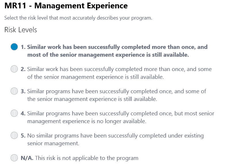
Figure 1. Identification of the Risk Level for Management Experience
If a program has experienced managers who have successfully completed a similar past program, then that program is low risk for the Management Experience item. Levels 3, 4, and 5 are more problematic, and additional effort is required to reduce the risk. It is recommended that all risks designated as Levels 3, 4 or 5 be examined further so that mitigation efforts can be undertaken, in alignment with program priorities and the availability of resources. A user chooses N/A if the judgment is made that the risk is not applicable to the program. We advise caution here also: often, upon further examination, the risk is actually applicable, so N/A should be chosen rarely. PRID outputs scores at the program, risk area, and individual risk area levels, facilitating progress tracking through time. Reporting capabilities include a list by risk level as well as numerical listing of risks by risk area. Reports are exported in a variety of formats (MS Word, Excel, PDF, CSV, XML, MHTML, and TIFF) to accommodate input to a wide variety of risk tools.
When two or more analyses for a given program are performed, PRID provides a trending capability so that previous analysis results can be compared with current analytical results so that risk mitigation efforts can be evaluated, and new identified risks can be addressed.
A summary of a case study using PRID involves a DoD Enterprise Resource Program (ERP) development program. The objective was to design, develop, prototype, and install an ERP program for a DoD agency. Installation of hardware and software elements occurred at multiple sites and required continuous communication between them. User training development and implementation across the agency was included in the program. Table 5 shows the initial and final program scores overall and for each risk area. The declining scores indicate that risk mitigation efforts through time are having a positive effort, since the lower the score the better. We also selected critical technical and operational risks to highlight in Table 6. As mitigation efforts progressed, risk levels were reduced for these risks (as well as others). A reduction in risk level corresponds to a reduction in the risk score, thus providing a means of measuring risk mitigation efforts through time.
| Table 5. DoD ERP Program Risk ID Analysis Results | ||||||||||||||||||||
Table 6. DoD ERP Risk Mitigation Path Via Subsequent Program Analyses
|
||||||||||||||||||||
Summary and Conclusions
We have presented in this paper an improved approach to risk identification based on an analysis of over 500 programs, their risks and outcomes, called the Risk Identification Analysis. The conclusions of the study include the emergence of 218 common program risks, risk levels for each risk, the identification of pertinent program complexity parameters and their effect upon the program risk profile. These conclusions provide an antidote to the serious problems that plague risk management today: the lack of a baseline to assist programs in identifying risks, thus addressing the short-comings associated with the ad-hoc, non-comprehensive, non-objective and non-standardized approach currently taken towards risk identification today.
A software tool based on this analysis has been shown to be useful anywhere risk identification is performed today for product and service development and modification. This approach has been used on product and service development/modification programs for numerous domains including aerospace, IT, and energy. It has been used on both commercial and government programs, including proposal efforts. It has been used on programs with various development approaches including Waterfall, Agile, Rapid Application Development, and Component-Based Development. This risk identification approach can be used on one program or on a portfolio of programs to compare risks across them directly.
List of Acronyms Used in this Paper
Acronym Explanation
CSV Comma Separated Values
DoD U.S. Department of Defense
ERP Enterprise Resource Program
FMEA Failure Modes Effects Analysis
GAO U.S. Government Accountability Office
MHTML MIME Hyper Text Markup Language
NASA National Aeronautics and Space Administration
N/A Non Applicable
PDF Portable Document Format
PRA Probabilistic Risk Assessment
PRID Program Risk ID
RM Risk Management
SE Systems Engineering
SME Subject Matter Expert
TIFF Tagged Image File Format
WBS Work Breakdown Structure
XML Extensible Markup Language
References
- ISO (International Organization for Standardization). 2009. ISO 31000:2009 – Risk Management — Principles and Guidelines. Geneva, CH: ISO.
- ISO (International Organization for Standardization). 2009. ISO/IEC 31010:2009 – Risk Management – Risk Assessment Techniques. Geneva, CH: ISO.
- ISO (International Organization for Standardization). 2009. ISO Guide 73:2009 – Risk Management – Vocabulary. Geneva, CH: ISO.
- FERMA (Federation of European Risk Management Associations). 2002. A Risk Management Standard. http://www.ferma.eu/risk-management/standards/risk-management-standard/
- OCEG (Open Compliance & Ethics Group). 2009. “Red Book” 2.0:2009 – GRC Capability Model.
- BSI (British Standards Institute). 2008. BS31100:2008 – Code of Practice for Risk Management. BSI.
- COSO (Committee of Sponsoring Organizations of the Treadway Commission). 2004. COSO: 2004 – Enterprise Risk Management – Integrated Framework. COSO.
- SOLVENCY. 2012. SOLVENCY II: 2012 – Risk Management for the Insurance Industry. Brussels: European Commission.
- DoDI (Department of Defense Instruction). 2014. DoDI 8510.01:2014 – Risk Management Framework (RMF) for DoD Information Technology (IT), March 12, 2014. Office of the Secretary of Defense.
- DoD. 2006. Risk Management Guide for DoD Acquisition, Version 6, August 2006. Office of the Secretary of Defense.
- Hall, D. 2011. “Making Risk Assessments More Comparable and Repeatable” Paper presented at the International Committee for Systems Engineering International Symposium, Denver, Colorado. Vol. 14, No. 2, pp 173-179.
- Taleb, N. 2007. The Black Swan: Second Edition: The Impact of the Highly Improbable. New York, US-NY: Random House.
- Acquisition Community Connection. Long Description Risk Identification Introduction.
- Ferreira, P. 2001. “Tracing Complexity Theory”. (On-line notes for ESD.83 – Research Seminar in Engineering Systems at MIT).
- Dann, Z. and I. Barclay. 2006. “Complexity Theory and Knowledge Management Application.” The Electronic Journal of Knowledge Management, Vol. 4, Issue 1, pp 11-20.
- Lehman, M. and L. Belady. 1985. Program Evolution: Processes of Software Change. San Diego, US-CA: Academic Press Professional, Inc.
- Henry, S. and D. Kafura. 1981. “Software Structure Metrics Based on Information Flow.” IEEE Transactions on Software Engineering, Volume SE-7, Issue 5, pp 510 – 518.
- Chidamber, S. and C. Kemerer. 1994. “A Metrics Suite for Object Oriented Design.” IEEE Transactions on Software Engineering, Vol. 20, Issue 6, Jun 1994, pp 476 – 493.
- Kearney, J., R. Sedlmeyer, W. Thompson, M. Gray, and M. Adler. 1986. “Software Complexity Measurement.” Communications of the ACM, November 1986, Volume 29, Number 11.
- Author: Magee, Christopher, M. and O. de Weck. 2004. “Complex System Classification.” INCOSE (International Council on Systems Engineering), 2004-07-24.
- Browning, T. 1998. “Sources of Schedule Risk in Complex Systems Development.” Proceedings of the 8Th annual Symposium of INCOSE, July 1998.
- Archstone Consulting. 2014. “Delays, Delays: A roadmap for improving performance across the Aerospace and Defense supply chain.”
- KPMG. 2010. “NZ Project managements survey 2010.”
- IBM. 2008, “Making Change Work.”
- KPMG. 2013. “Project Management Survey Report 2013.”
- Parker, D. and M. Craig. 2008. Managing Projects, Managing People. UK-London: Palgrave MacMillian. p 139.
- Sysenex. 2013. “PRID Risk Management Survey Report, Executive Summary.” https://programriskid.com/resources/
- NASA. 2007. NASA/SP-2007-6105, Rev 1 – NASA Systems Engineering Handbook. December, 2007.
- NASA. 2007. NPR 7123.1A – Systems Engineering Process and Requirements, App. C. March 26, 2007.
- NASA. 2011. NASA/SP-2011-3422 – NASA Risk Mgmt. Handbook. December 21, 2011.
- Institution of Engineers Australia. 2005. Engineers Australia Risk Management Strategies Guide. July, 2005
- NASA. 2008. NPR 8705.2- Human-Rating Requirements for Space Systems. May 6, 2008.
- FFIEC (Federal Financial Institutions Examination Council). 2004. FFIEC Management IT Examination Handbook. June, 2004.
- NASA. 2008. NPR 8715.3 – NASA General Safety Program Requirements. March 12, 2008.
Article
What a High Performing Team Looks Like and How to Create One
High performing is a team property, a temporary state which needs attention if teams want to keep on performing well. Things you can do to build a high performing team include creating safety, investing in developing collaboration skills, and giving peer-to-peer feedback.
Patrick Kua, principal consultant and tech lead at ThoughtWorks, spoke about building a high performing team at QCon London 2017. InfoQ is covering this conference with Q&As, summaries and articles. Kua explained the difference between a group of people and a team. In a group people have individual goals and most of the time they are not working together. People in teams work towards a shared goal and they get rewarded as a team for reaching it.
In high performing teams there can be conflicts, which may sound counterintuitive, said Kua. When people work intensively together conflicts arise and teams have to deal with them. Kua gave an example of dysfunctional behavior in teams where someone changes the code that someone else wrote, and then the person who wrote it changes it back. But by doing so people are avoiding conflict, which is not good, he said. Good conflicts involve healthy discussions; teams need to be in an atmosphere to make this possible.
Leadership is taking an act and helping people to come along with this act, said Kua. He suggested to encourage leadership at all levels, and have people think about what is it that they can do to help the team.
We can use systems thinking to understand and improve how teams work. A team is a group of people working together. The behavior is unpredictable; no two teams are the same, said Kua. High performing is a team property. It is only a temporary state; it needs attention if teams want to keep on performing well.
Teams have emergent behavior which is based on their interactions. Kua suggested to invest in developing collaboration skills, preferably the ones that team members can apply in their daily work.
Teams can do “ways of working sessions” to define and agree how they want to work together. But often teams get stuck in the brainstorming phase discussing different approaches. Kua suggested to set expectations on what to do and how to work at the start, and let individuals share what they think is important. It can be worthwhile revisiting your way of working after some time, as things will change along the way.
Teams have to create safety in order to talk about things that involve everyone. Kua mentioned the “prime directive” from Norm Kerth which can be used to create a safe environment. Teams can experiment with change; if it goes wrong then they can go back to how they did things before. Kua suggested to take small steps and focus on improving the interactions between team members.
Peer-to-peer feedback can help teams to improve daily interaction between members. Kua suggested to do it frequently; as a minimum every person should get and give feedback once every month. He also suggested to train people on giving effective feedback.
You should look for people with different backgrounds and different skills when forming teams. Diversity matters, said Kua. He suggested to “look for different DNA”. A tool that you can use is “moving motivators” from management 3.0. Kua stated that we should appreciate differences and explore contexts where traits are useful.
Article
Integrating Program Management and Systems Engineering
by
Dr. Ralph R. Young, Editor, SyEN
This month we provide a summary of Chapter 3 in Integrating Program Management and Systems Engineering (IPMSE), a collaboration of the International Council on Systems Engineering (INCOSE), the Project Management Institute (PMI), and the Consortium for Engineering Program Excellence (CEPE) at the Massachusetts (USA) Institute of Technology (MIT).
Chapter 3 of this new and profound book is titled “The Features of Successful Integration of Program Management and Systems Engineering”. This chapter emphasizes that when the success of a program is expanded with a more comprehensive focus on the benefits realized, the program may be seen in a different light. A good example is the Boston Central Artery/Tunnel (aka “The Big Dig”) that accomplished a complete restructuring of Boston’s central roadways, greatly improving the flow of traffic and opening up areas of the city for new development. In addition, new best practices and unprecedented approaches to engineering major infrastructure programs were developed. Engineering programs such as The Big Dig may always risk being deemed failures if they are evaluated simply on measures of cost and schedule. A key point is that the roles of chief systems engineer and program manager are much broader than they may appear.
Several highly successful engineering programs were identified early in the research that was performed in connection with development of the book. Researchers were particularly interested in identifying and describing how the joint contributions of systems engineering and program management were leveraged to provide superb results. A set of principles (key success contributors) were identified:
- Vision – effective program management set a vision and kept the team focused on program goals.
- Continuous block and tackle – program sponsors and leadership played both offensive and defensive roles as program protectors, including actively and regularly engaging stakeholders and insulating programs from disruptive requirements changes.
- Building empowered, collaborative teams and establishing the right program culture. Leaders and managers created an environment where individuals from different disciplinary approaches, perspectives, and roles knew how to collaborate, negotiate, and accept decisions once they were made.
- Program governance – review meetings were held to ensure that the program aligned with objectives.
- Smooth engineering management – the critical connection of program management and technical management was enacted. Successful integration requires intentional actions of team members to achieve alignment: working together.
- Members of the program team held each other accountable for program performance.
Readers might consider from the perspective of one’s own experience: what comes to mind when you think of a successful program? On programs in which you have been involved, what led to success or failure?
INCOSE International Events
The 2017 INCOSE International Symposium (IS) is reported to have been a big success! More than 600 attendees were welcomed to Adelaide, Australia for nearly a week of fruitful knowledge transfer, technical discussions and networking.
Planning for upcoming international events is in full swing. The 2018 International Symposium in Washington, DC promises to be an attendance record breaker! INCOSE has posted a call for submissions on the IS 2018 website, with a due date of November 10, 2017 (http://www.incose.org/symp2018).
The INCOSE Board of Directors (BOD) has made the decision to move the 2019 International Workshop (IW) back to Torrance, CA. They are also exploring options for a stronger global presence for the workshop. This includes looking for a satellite location in the EMEA Sector for 2019 to complement the IW in Torrance, and finding a location for a future IW to be held in EMEA.
INCOSE 2017 International Symposium Keynotes
Did you miss the INCOSE International Symposium? Did you attend the symposium and want to view the keynotes again or share them with a colleague? All keynote addresses are now posted on the INCOSE YouTube site.
- AVM Mel Hupfeld – Force Design: Evolution not revolution
- Dr. Tomohiko Taniguchi – The Japanese Bullet Train “Shinkansen” System: Its Genesis and Safety Assurance
- Paul Nielsen – Systems Engineering and Autonomy: Opportunities and Challenges
- Bill Murtagh – Space Weather: Understanding and Mitigating Impacts on Our Interconnected and Interdependent Critical Infrastructure
INCOSE Call for Nominations for Pioneer, Founder and Outstanding Service Awards
INCOSE has announced opportunities to nominate individuals for the Pioneer, Founder and Outstanding Service awards.
INCOSE Nominations & Elections Presents 2017 Slate of Candidates
On November 1, members in good standing on October 1 (students are not eligible to vote), will have the opportunity to vote for positions listed below with the successful candidates installed in office at the 2018 International Workshop. We are happy to present this year’s slate of candidates. Each candidates vision and bio can be accessed by clicking on their name
Position (Term of Office)
- President-Elect (Term: 2 yrs Pres-Elect / 2 yrs President)
Kerry Lunney
Paul Schreinemakers - Treasurer (2 yrs)
Rene Oosthuizen
Michael Vinarcik - Chief Information Officer (CIO) (3 yrs)
Bill Chown
Robert Edson - Director for Outreach (3 yrs)
Gina Guillaume-Joseph
The SDL Forum Returns
The System Design Language (SDL) Forum returns this year for its 18th instalment in Budapest, Hungary, from the 9th to 11th of October 2017. This event is undoubtedly a highlight on the calendar of individuals with a career or interest related to SDL and/or modelling techniques. SDL is a specification and description language initially standardised by the International Telecommunication Union (ITU) for modelling telecommunication systems, but has also been used in diverse application areas such as aircraft, train control and packaging systems. SDL is widely used in Model-Based Systems Engineering (MBSE) for the expression and representation of systems phenomena. The language enables understanding and insight to be gleaned about the system or attribute due to the unambiguous representation of relevant entities and relationships.
The conference entails a deliberation between users, experts, toolmakers and critics on the latest developments in the field of SDL and modelling. Particular areas of focus for the conference includes: modelling and specification of systems and software, and, analysis of distributed, embedded, communication and real-time systems. The SDL Forum is facilitated by the SDL Forum Society – a non-profit organisation established by SDL users and SDL tool developers aimed at promoting the use of languages such as UML, SysML, TTCN, URN and ASN. Each year the conference has a theme pertinent to the zeitgeist of the global networked ecosystem during that year. This year, the theme is ‘Model-driven Engineering for Future Internet’. Registration for the conference can be done through the following link: http://www.sdl2017.hte.hu/registration.
The biennial event was last held in October, 2015 in Berlin, with the theme ‘Model-Driven Engineering for Smart Cities’. More information on the SDL Forum and the SDL Forum Society is available on the SDL website at http://sdl-forum.org.
National Renewable Energy Laboratory (NREL) Provides Systems Engineering News
The National Renewable Energy Laboratory (NREL) is a national laboratory of the U.S. Department of Energy, Office of Energy Efficiency and Renewable Energy, operated by the Alliance for Sustainable Energy, LLC. The Wind Plant Optimization and Systems Engineering newsletter covers the latest research, technology, and software development activities about systems engineering. Topics range from multi-disciplinary design analysis and optimization of wind turbine sub-components to wind plant optimization and uncertainty analysis to concurrent engineering and financial engineering.
When Aerospace Met Oil & Gas at the INCOSE Texas Gulf Coast Systems Engineering Conference
A sold-out audience of 120 people from the Aerospace and Oil & Gas industries attended the International Council on Systems Engineering (INCOSE) Texas Gulf Coast Chapter (TGCC) Inaugural Conference in Houston on May 5, 2017.
“Systems Engineering will fundamentally reshape the way we work, empower our people to unlock productivity, and unleash creativity. It will allow us to have better solutions that increase both our performance and competitiveness.”
– Robert Patterson, Shell Executive Vice President, Engineering
Overall, the inaugural event was a success with participants attending a full day of technical sessions on important topics related to Systems Engineering in the industries.
Read more about the event here.
Stevens Professor Receives NSF Grant for Collective Design in Systems Engineering
Dr. Paul Grogan, assistant professor of systems engineering at Stevens Institute of Technology, has been awarded a National Science Foundation (NSF) Systems Science grant which may have broad impacts on the design and management of large scale systems. The $120,000 award is funded under the EAGER (Early-concept Grants for Exploratory Research) program, which is a special program for high-risk, high potential reward research.
A member of the research faculty at the Stevens School of Systems and Enterprises (SSE), Grogan is focused on researching and developing information-based tools for engineering design in domains with distributed system architectures such as aerospace and defense. Now in its tenth year, SSE aims to address complexity in modern systems, one of the most pressing issues in an increasingly connected global society.
The purpose of Grogan’s new project is to research a systems design approach centered on value. The way most systems engineering projects are managed, it starts with a set of requirements that a customer or key stakeholder defines. These requirements are the high-level needs that the design must satisfy. Historically, this approach has worked very well, but there are downsides according to Grogan.
“By setting up very clear requirements, you prevent yourself from exploring possible designs that may do better in certain dimensions,” he explains. “Over the last 10 years there has been an initiative growing out of different organizations to transition from a requirements driven design approach to a value-driven design approach.”
The aim of the value-driven design process is to essentially maximize value rather than minimizing costs or meeting certain requirements. Instead of stating main requirements, characteristics that provide value on the system become the driving force behind the design process.
Building on a game theory model of systems design, the project will develop a mathematical framework to characterize a multi-actor system design problem as a set of decisions and value flows contributing to strategic behavior.
“It’s really exciting to be able to pursue this idea that I’ve been developing for the past couple of years with support of the NSF,” says Grogan, who often uses gaming approaches in his research and when teaching Stevens students to demonstrate technical simulation models inside a social decision-making activity.
United States Department of Defense Announces Recipients of Value Engineering Achievement Awards
As part of the U.S. Department of Defense (DoD) Honorary Value Engineering (VE) Awards Program, 24 recipients were honored with DoD VE Achievement Awards for fiscal year 2016 in a July 18 ceremony in the Pentagon auditorium held on behalf of the Office of the Under Secretary of Defense for Acquisition, Technology and Logistics.
Kristen Baldwin, acting deputy assistant secretary of defense for systems engineering, praises engineering efforts in fiscal year 2016 that reduced cost, speeded delivery, and enhanced the performance of the equipment and services provided to U.S. fighting forces in fiscal year 2016 during a ceremony at the Pentagon for the Department of Defense Honorary Value Engineering Awards Program, July 18, 2017. Ms. Baldwin remarked that “for decades, value engineering has played an integral role in accomplishing the Department’s mission to provide the military forces needed to deter war and to protect the security of our country.”
Value engineering was born out of innovative material and design alternatives that resulted from the material shortages of World War II. DoD uses value engineering to analyze supplies, services, buildings, and systems to achieve best value, or the best relationship between worth and cost consistent with required performance, quality, and safety of essential functions. Value engineering efforts reduce cost, speed delivery, and enhance the performance of the equipment and services provided to U.S. forces, she said. Awards honored efforts that resulted in cost savings or cost avoidances, quality improvements, or efficiencies to the DoD.
Featured OrganizationS
National Defense Industrial Association (NDIA) Systems Engineering Division
Mission
NDIA’s Systems Engineering Division advocates the widespread use of systems engineering in the Defense Department acquisition process to achieve affordable, supportable and interoperable weapon systems that meet the needs of military users; supports the open exchange of ideas and concepts between government and industry; and works for a new understanding of a streamlined systems engineering process.
The Division is a central link between industry and the Defense Department and performs vital collaborative work across a broad range of areas. The NDIA Systems Engineering Division works closely with other organizations such as INCOSE to foster effective application of systems engineering principles. In addition it hosts an annual Systems Engineering conference that is the premier event for systems engineering practitioners in the Defense arena.
Objective
The division’s goals include:
- Effecting good technical and business practices within the aerospace and defense industry.
- Improving delivered system performance, including supportability, sustainability and affordability.
- Emphasizing excellence in systems engineering throughout the program life cycle and across all engineering disciplines and support functions.
The Design Society
The Design Society is an international non-governmental, non-profit making organization whose members share a common interest in design. It strives to contribute to a broad and established understanding of all aspects of design, and to promote the use of results and knowledge for the good of humanity.
Objectives
The objectives of the Society are to promote the development and promulgation of understanding of all aspects of design across all disciplines by:
- Creating and evolving a formal body of knowledge about design;
- Actively supporting and improving design research, practice, management and education;
- Promoting co-operation between those in research, practice, management and education;
- Promoting publications and their dissemination;
- Organizing international and national conferences and workshops;
- Establishing Special Interest Groups and other specialist activities;
- Cooperating with other bodies with complementary areas of interest.
INCOSE Complex Systems Working Group
The purpose of the Complex Systems Working Group is to enhance the ability of the systems engineering community to deal with complexity. The Complex Systems Working Group works at the intersection of complex systems sciences and systems engineering, focusing on systems beyond those for which traditional systems engineering approaches and methods were developed.
The Complex Systems Working Group focuses on the challenges and opportunities presented by systems with large numbers of components, with even greater numbers of interactions distributed in scope across multiple scales and/or across large areas. Systems of interest are characterized by rich interdependence among diverse components, non-linearity, open systems boundaries, networks of causality and influence (vice linear causal chains), emergence, varied and changing system goals, self-organization, and multi-level adaptation. These traits limit the utility of traditional systems engineering paradigms, which are generally centralized, goal oriented, requirements driven, and reductionist in approach. These traits, however, are increasingly the norm and not the exception. The Complex Systems Working Group collaborates with the Systems Sciences Working Group to define the scientific basis of these characteristics.
Further, complexity is a characteristic of more than just a technical system being developed. The socio-technical ecosystem in which a system under development will be employed exhibits these attributes, as does the environment that gave rise to the challenge or opportunity to which the system was developed in response. Further, the design and development of technical systems is a complex endeavor itself. It is critical for systems engineers to understand the nature of the systems with which they are working, and of which they are a part, to be effective.
The goals of the Complex Systems Working Group are to communicate the complexity characteristics to systems engineering practitioners, provide knowledge and expertise on complex systems in support of other INCOSE working groups working in their systems engineering areas, facilitate the identification of tools and techniques to apply in the engineering of complex systems, and provide a map of the current, diverse literature concerning complex systems to those interested in gaining an understanding of complexity.
To learn more or inquire about participation in this working group, contact Dr. Jimmie McEver at jimmie.mcever@jhuapl.edu. For more information on the working group, visit this web page.
For more information on systems engineering related conferences and meetings, please proceed to our website.
Some Systems Engineering-Relevant Websites
Modern Analyst
Modern Analysis is intended to be of use to training providers, experienced practitioners, tool vendors or recruiters with a focus on business system analysis. The site contains many articles and resources related to business systems analysis, including the monthly Modern Analysis Journal which highlights events, forums, blogs and a host of other information relevant to the industry at the time of release.
Mind Tools
Mind Tools, established in 1996, is a website dedicated to helping people excel in the fast-paced world of today. By becoming a Mind Tool Club member, users are equipped to develop skills and techniques typically taught in MBA classes or management programs. The tools are specifically geared to assist users in improving their career performance with over 2500 skill-building resources that offer exclusive training on topics such as: management and leadership skills, career planning and time management. To date more than 140 000 professionals have made use of the website and learnt the principles practiced by successful business managers. The tools may be trialed for a price $1 for the first month.
Model Based Systems Engineering
This website was developed by a German consultant and owner of MBSE4U- a lean publishing house with MBSE books and content that follows the dynamic changes of the MBSE community and market. The website specifically discusses books and content introduced by its creator, specifically- SYSMOD- Systems Modelling Toolbox andVAMOS (Variant Modelling with SysML). SYSMOD presents a pragmatic approach to modelling the requirements and system architecture of a system. The VAMOS method presents a process for modelling variants with SysML. The website contains blog posts, articles and free downloads related to SysML- a useful site for any person who makes use of SysML or modelling variants in their practice.
http://model-based-systems-engineering.com
Systems Engineering Publications
Engineering a Safer World

by
Nancy G Leveson
Book Description (from the Amazon web site):
Engineering has experienced a technological revolution, but the basic engineering techniques applied in safety and reliability engineering, created in a simpler, analog world, have changed very little over the years. In this groundbreaking book, Nancy Leveson proposes a new approach to safety — more suited to today’s complex, sociotechnical, software-intensive world — based on modern systems thinking and systems theory. Revisiting and updating ideas pioneered by 1950s aerospace engineers in their System Safety concept, and testing her new model extensively on real-world examples, Leveson has created a new approach to safety that is more effective, less expensive, and easier to use than current techniques.
Arguing that traditional models of causality are inadequate, Leveson presents a new, extended model of causation (Systems-Theoretic Accident Model and Processes, or STAMP), then then shows how the new model can be used to create techniques for system safety engineering, including accident analysis, hazard analysis, system design, safety in operations, and management of safety-critical systems. She applies the new techniques to real-world events including the friendly-fire loss of a U.S. Blackhawk helicopter in the first Gulf War; the Vioxx recall; the U.S. Navy SUBSAFE program; and the bacterial contamination of a public water supply in a Canadian town. Leveson’s approach is relevant even beyond safety engineering, offering techniques for “reengineering” any large sociotechnical system to improve safety and manage risk.
Flexibility in Engineering Design

by
Richard de Neufville and Stefan Scholtes
Book Description (from the Amazon web site):
Project teams can improve results by recognizing that the future is inevitably uncertain and that by creating flexible designs they can adapt to eventualities. This approach enables them to take advantage of new opportunities and avoid harmful losses. Designers of complex, long-lasting projects — such as communication networks, power plants, or hospitals — must learn to abandon fixed specifications and narrow forecasts. They need to avoid the “flaw of averages,” the conceptual pitfall that traps so many designs in underperformance. Failure to allow for changing circumstances risks leaving significant value untapped. This book is a guide for creating and implementing value-enhancing flexibility in design. It will be an essential resource for all participants in the development and operation of technological systems: designers, managers, financial analysts, investors, regulators, and academics.
The book provides a high-level overview of why flexibility in design is needed to deliver significantly increased value. It describes in detail methods to identify, select, and implement useful flexibility. The book is unique in that it explicitly recognizes that future outcomes are uncertain. It thus presents forecasting, analysis, and evaluation tools especially suited to this reality. Appendixes provide expanded explanations of concepts and analytic tools.
Applied Minds: How Engineers Think
by
Guru Madhavan
Book Description (from the Amazon web site):
Applied Minds explores the unique visions and mental tools of engineers to reveal the enormous―and often understated―influence they wield in transforming problems into opportunities. The resulting account pairs the innovators of modern history―Thomas Edison, the Wright brothers, Steve Jobs―with everything from ATMs and the ZIP code system to the disposable diaper.
An engineer himself, Guru Madhavan introduces a flexible intellectual tool kit called modular systems thinking as he explains the discipline’s penchant for seeing structure where there is none. The creations that result from this process express the engineer’s answers to the fundamental questions of design: usefulness, functionality, reliability, and user friendliness.
Through narratives and case studies spanning the brilliant history of engineering, Madhavan shows how the concepts of prototyping, efficiency, reliability, standards, optimization, and feedback are put to use in fields as diverse as transportation, retail, health care, and entertainment.
Equal parts personal, practical, and profound, Applied Minds charts a path to a future where we apply strategies borrowed from engineering to create useful and inspired solutions to our most pressing challenges.
Systems Thinking for Social Change: A Practical Guide to Solving Complex Problems, Avoiding Unintended Consequences, and Achieving Lasting Results
by
David Peter Stroh
Book Description (from the Amazon web site):
Donors, leaders of nonprofits, and public policy makers usually have the best of intentions to serve society and improve social conditions. But often their solutions fall far short of what they want to accomplish and what is truly needed. Moreover, the answers they propose and fund often produce the opposite of what they want over time. We end up with temporary shelters that increase homelessness, drug busts that increase drug-related crime, or food aid that increases starvation.
How do these unintended consequences come about and how can we avoid them? By applying conventional thinking to complex social problems, we often perpetuate the very problems we try so hard to solve, but it is possible to think differently, and get different results.
Systems Thinking for Social Change enables readers to contribute more effectively to society by helping them understand what systems thinking is and why it is so important in their work. It also gives concrete guidance on how to incorporate systems thinking in problem solving, decision making, and strategic planning without becoming a technical expert.
Systems thinking leader David Stroh walks readers through techniques he has used to help people improve their efforts to end homelessness, improve public health, strengthen education, design a system for early childhood development, protect child welfare, develop rural economies, facilitate the reentry of formerly incarcerated people into society, resolve identity-based conflicts, and more.
The result is a highly readable, effective guide to understanding systems and using that knowledge to get the results you want.
Communicate Like a Leader: Connecting Strategically to Coach, Inspire, and Get Things Done
by
Dianna Booher
Book Description (from the Amazon web site):
Dianna Booher wants to prevent micromanagement before it happens by providing you with the right leadership communication skills. Grounded in extensive research, this book offers practical guidelines to help professionals think, coach, converse, speak, write, meet, and negotiate strategically to deliver results. In thirty-six brief chapters, Booher shows you how to communicate effectively to audiences up and down the organization so you can fulfill your most essential responsibilities as a leader.
Systems Engineering Tools News
Cradle 7.3
Cradle® is a requirements management and systems engineering software tool by 3SL in the UK.
Version 7.3 of Cradle has just been released in August. Some of the highlights are:
- Metrics – Calculations on metric results
- Configuration Management – Related item submissions
- Categories – Skill based control
- Link rules – Cardinality control
- Item Ownership – Set item ownership of item’s related items
- New Cradle and Toolsuite installers
Existing Cradle users will need a new Security Code for Cradle-7.3, other Security Codes cannot be used. You must upgrade all Cradle installations to 7.3. Cradle-7.2 clients cannot connect to a Cradle-7.3 server, and a Cradle-7.3 server cannot serve Cradle-7.2 clients.
Education and Academia
Engineering Education Needs a ‘Major Shake up’
Technologies – and therefore skills needs – are evolving fast; politicians are rarely focused on constantly updating the required educational infrastructure; and teaching ‘soft skills’ – such as creativity, analytical thinking, multitasking, communication, and adaptability – is not that easy. To meet these challenges requires a shake-up of traditional education models, may require the development of new qualifications, and will force students, teachers and employers to discard entrenched attitudes to learning.
James Plummer, engineering professor and former dean at Stanford University, California (USA) says undergraduate engineering courses should be broadened to include liberal arts and life skills, so that students are better prepared for the unpredictable careers the future will throw at them. He believes graduates will be best served by acquiring better communication skills, the ability to work in teams, gaining global knowledge, and having an entrepreneurial outlook.
INCOSE Initiative to Establish ISO Standards for Feature-Based Product Line Engineering
The International Council on Systems Engineering (INCOSE) will lead the development of new ISO standards for feature-based Product Line Engineering (PLE). Dr. Charles Krueger, CEO of BigLever Software, will assemble experts from to develop a disciplined, structured set of standards that can be applied to help engineering organizations implement the most efficient, effective, and proven modern PLE approaches.
“Feature-based PLE is emerging as one of the foremost areas of innovation within the systems engineering field today,” said Krueger. “These new ISO standards will clearly define the modern PLE approaches that are enabling the industry’s most notable PLE success stories. Feature-based PLE provides a fully unified, automated approach across engineering and operations disciplines, tools and processes – allowing organizations to create and bring more product innovations to market faster, more efficiently, and more competitively.”
“Product Line Engineering has become a critical technology that will have broad impact across the systems engineering field,” said Dr. Gina Guillaume-Joseph, assistant director, Standards Initiatives, INCOSE. “It is important to the community that we facilitate awareness and understanding of the latest PLE approaches and proven best practices. We are excited to have industry leader and PLE pioneer Dr. Krueger leading our effort to establish the new Feature-based PLE standards, as well as helping to promote their widespread adoption.”
As market demand for product sophistication and diversity continues to grow, companies face new levels of systems engineering complexity. It is not unusual for engineering teams to spend as much as two-thirds of their time dealing with the mundane tasks of managing the mounting complexity of product variation. PLE addresses product complexity by dramatically simplifying the creation, delivery, maintenance, and evolution of a product line portfolio. Feature-based PLE enables a unified approach across the full lifecycle, from portfolio planning to multi-discipline asset engineering, product marketing, manufacturing, sales, and service. By providing a “single source of feature truth,” modern PLE enables a holistic view into the feature variations for a product family, eliminating the need for different variant management mechanisms across the organization.
The new PLE standards will delineate the specialization of state-of-the-art PLE approaches where featured-based automation is used to remove the complexities that existed with early-generation PLE techniques. These techniques, such as asset cloning, branching and merging, created barriers to PLE adoption in the past.
ISO/IEC/IEEE 21839 — Systems of Systems Considerations in Life Cycle Stages of a System
The committee draft of ISO/IEC/IEEE 21839 – Systems of systems considerations in life cycle stages of a system (CD2) is out for review. There is not much time left, but readers who would like to participate in the review could contact their National Standards body in the first instance.
ISO/IEC 90003 Software Engineering — Guidelines for the Application of ISO 9001:2015 to Computer Software
Draft International Standard (DIS) ISO /IEC 90003 Software Engineering — Guidelines for the application of ISO 9001:2015 to computer software was recently distributed for comment within the ISO standards development process. This standard being proposed as an update to the extant ISO/IEC 90003:2014 (based on ISO 9001:2008) for distribution as an International Standard.
ISO/IEC 15026-4 Systems and Software Engineering—Systems and Software assurance — Part 4: Assurance in the Life Cycle
A Committee Draft (CD) of ISO-IEC CD 15026-4 Systems and software engineering—Systems and software assurance — Part 4: Assurance in the life cycle was recently distributed for comment within the ISO standards development process. This standard being updated in order to maintain consistency with ISO/IEC/IEEE 15288:2015, and the ongoing revision of ISO/IEC/IEEE 12207.
ISO/IEC/IEEE DIS 24748-2 Systems and Software Engineering — Life Cycle Management — Part 2: Guidelines to the Application of ISO/IEC/IEEE 15288
The Draft International Standard (DIS) ISO/IEC/IEEE DIS 24748-2 Systems and software engineering — Life cycle management — Part 2: Guidelines to the application of ISO/IEC/IEEE 15288 (System life cycle processes) was recently released for comment within the ISO standards development process.
ISO/IEC/IEEE 16085 Systems and Software Engineering — Life Cycle Processes — Risk Management
A Working Draft (WD) of ISO/IEC/IEEE 16085 Systems and software engineering — Life cycle processes — Risk management was recently released for comment within the ISO standards development process. The standard aims to replace the current version ISO/IEC 16085:2006 in order to:
- align it with:
- ISO 31000:201x, Risk management — Principles and guidelines (currently in the process of update),
- ISO/IEC/IEEE 15288:2015, Systems and software engineering —System life cycle processes,
- ISO/IEC/IEEE 12207:201x, Systems and software engineering — Software life cycle processes (currently in the process of update, at FDIS stage),
- ISO/IEC/IEEE 16326:201x, Systems and software engineering — Life cycle processes — Project management (currently in the process of update);
- add content to more completely and clearly address unique additional risk management challenges inherent to large complex systems engineering programs and projects, particularity those which are sociotechnical in scope, involving organizational and environmental (context) related issues;
- provide a limited number of annexes containing particularly useful templates or reference guides, such as a risk management plan template, risk modelling, and risk management framework design; and
- remove or update outdated content.
ISO/IEC/IEEE 42010 Systems and Software Engineering — Architecture Description
Working Group WG 42 of ISO JTC1/SC7 is undertaking a revision to the standard ISO/IEC/IEEE 42010 Systems and software engineering — Architecture description.
The Working Group has issued a Call for Comments to users of the current edition of the standard, the 2011 Edition. These comments will be taken into consideration in the upcoming revision.
This International Standard codifies key aspects of current practice for the description of architectures. The International Standard is applicable to the architectures of enterprises, products (goods or services), systems, and software, including systems of systems, product lines and families.
The (current edition of the) Standard:
- specifies the manner in which architecture descriptions are organized and expressed;
- specifies architecture viewpoints, architecture frameworks and architecture description languages for use in architecture descriptions; and
- also provides motivations for terms and concepts used; presents guidance on specifying architecture viewpoints; and demonstrates the use of this International Standard with other standards.
The revision will undertake any necessary corrections and clarifications based upon the past five years of usage of the 2011 edition. The revision will also seek to incorporate improvements to the practices of Architecture description that have come into use since the previous edition. The website for this standard is http://www.iso-architecture.org/ieee-1471/.
Readers who would like to participate in the review may contact their National Standards body in the first instance, or if IEEE members, may participate through that Society.
ISO/IEC/IEEE 42030 Systems and Software Engineering — Architecture Evaluation
A Draft of International Standard ISO/IEC/IEEE 42030 Systems and software engineering — Architecture Evaluation was recently released for balloting within the ISO standards development process.
What is Product Line Engineering (PLE)?
Product Line Engineering (PLE) is a way to engineer a portfolio of related products in an efficient manner, taking advantage of products’ similarities while managing their differences. Engineering includes all the activities involved in planning, producing, delivering, deploying, sustaining, and even retiring products.
PLE considers the product line portfolio as a single entity to be managed, as opposed to a multitude of similar but separate products. By exploiting product commonality while managing variation, organizations can achieve improvements in effort, time, and quality. This enables a unified, automated approach across the entire life cycle – including engineering and operations disciplines; software, electrical, and mechanical domains; and tool ecosystems.
Systems Engineering Training in Indonesia
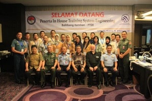
Bandung Delegates
Indonesia became the 36th country of the world in which PPI has delivered its systems engineering training, with delivery of a five-day course/workshop in Bandung in September 2017. The course was delivered to a group of 20 industry and government delegates with roles as engineers, managers and policy-makers in a large, technology-intensive project intended for completion by 2026.
The course, delivered by PPI Managing Director and SE discipline leader Robert Halligan FIE Aust CPEng, received outstanding feedback from delegates, and aligns with a decision by the project owner to apply systems engineering principles and methods in moving the project forward.
Bandung, capital of Indonesia’s West Java province, is a large city set amid volcanoes and tea plantations. It’s known for colonial and art deco architecture, a lively, university-town feel, and, thanks to its 768m elevation, a relatively cooler tropical climate.
PPI Delivers Systems Engineering Training in Sudan
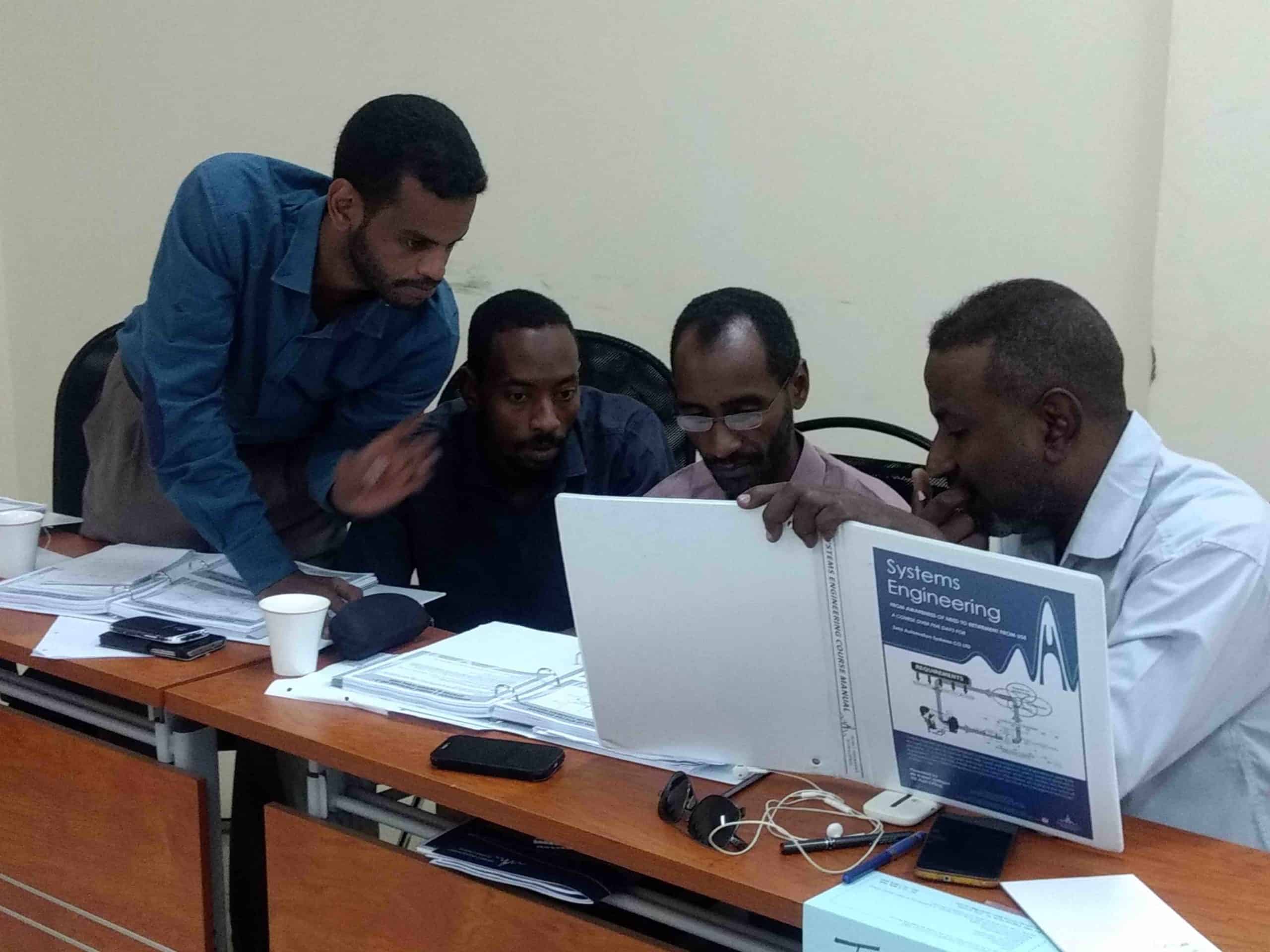

Sudanese Delegates
Sudan became the 37th country of the world in which PPI has delivered its systems engineering training, with delivery of a five day course/workshop in Khartoum at the end of September 2017. The course was delivered to a group of 12 engineers from a leading Sudanese industrial group with products in the fields of industrial control, water management and water treatment.
The course was delivered by PPI Managing Director and SE discipline leader Robert Halligan FIE Aust CPEng. Robert’s reaction to his visit to Sudan: “I have never before visited a country with so many smiling, friendly, hospitable people. They were a joy to be with, and an education.”
Khartoum is the capital and largest city of Sudan, in the North-East of the African continent. It is located where the White Nile, flowing north from Lake Victoria, and the Blue Nile, flowing west from Ethiopia, merge. The city has a population of over 5 million people.
Upcoming PPI and CTI Participation in Professional Conferences
PPI will be participating in the following upcoming events.
36th International Conference on Conceptual Modeling (ER 2017)
6 – 9 November 2017
Valencia, Spain
INCOSE UK, Annual Systems Engineering Conference (ASEC) 2017
(Exhibiting)
21 – 22 November 2017
Warwick, UK
12 – 13 December 2017
PPI and CTI Events
Systems Engineering 5-Day Courses
Upcoming locations include:
- London, United Kingdom
- Pretoria, South Africa
- New York, NY, United Stated of America
Requirements Analysis and Specification Writing 5-Day Courses
Upcoming locations include:
- Las Vegas, NV, United States of America
- Amsterdam, the Netherlands
- Adelaide, Australia
Systems Engineering Management 5-Day Courses
Upcoming locations include:
- London, United Kingdom
- Stellenbosch, South Africa
- Melbourne, Australia
Requirements, OCD and CONOPS in Military Capability Development 5-Day Courses
Upcoming locations include:
- Amsterdam, the Netherlands
- Ankara, Turkey
Architectural Design 5-Day Course
Upcoming locations include:
- London, United Kingdom
- Pretoria, South Africa
- Stellenbosch, South Africa
Software Engineering 5-Day CoursesUpcoming locations include:
- Pretoria, South Africa
- London, United Kingdom
- Las Vegas, NV, United States of America
Human Systems Integration Public 5-Day Courses
Upcoming locations include:
- Sydney, Australia
- Melbourne, Australia
CSEP Preparation 5-Day Courses (Presented by Certification Training International, a PPI company)
Upcoming locations include:
- Chantilly, VA, United States of America
- Madrid, Spain
- Pretoria, South Africa
Kind regards from the SyEN team:
Robert Halligan, Editor-in-Chief, email: rhalligan@ppi-int.com
Dr. Ralph Young, Editor, email: ryoung@ppi-int.com
Suja Joseph-Malherbe, Managing Editor, email: smalherbe@ppi-int.com
Project Performance International
2 Parkgate Drive, Ringwood North, Vic 3134 Australia Tel: +61 3 9876 7345 Fax: +61 3 9876 2664
Tel Brasil: +55 11 3958 8064
Tel UK: +44 20 3608 6754
Tel USA: +1 888 772 5174
Web: www.ppi-int.com
Email: contact@ppi-int.com
Copyright 2012-2017 Project Performance (Australia) Pty Ltd, trading as Project Performance International.
Tell us what you think of SyEN. Email us at syen@ppi-int.info.
- The Coordinator Role as a troubleshooter: “Even if there are no “systems engineers,” coordination can be considered vital to the engineering of a complete system. This role may be permanent, defined in terms of team or discipline coordination, or transitory, established to solve a specific problem and then dissolved” (Sheard, 2013). ↑
- The Integrator (Glue among Subsystems) as a troubleshooter: “In this [Glue] role, the systems engineer serves as a proactive troubleshooter, looking for problems and arranging to prevent them” (Sheard, 2013). ↑
- https://www.iso.org/standard/62274.html ↑
- KPMG is a professional service company and one of the Big Four auditors, along with Deloitte, Ernst & Young (EY), and PricewaterhouseCoopers (PwC). ↑