IN THIS EDITION
1. Quotations to Open On
2. Feature Article
2.1 Accelerating Model Development and Consistency: The SAIC Digital Engineering Validation Tool by Michael J. Vinarcik
2.2 Overview of Recent Systems Engineering Guidance Provided by the National Aeronautics and Space Administration (USA) by Ralph Young
3. Notable Articles
3.1 Leading the Transformation of Model-based Engineering by Al Hoheb
3.2 Three Ways to Simplify Complex Projects by Dave Wakeman
3.3 The Test Like You Fly (TLYF) Process – Creating Operationally Realistic Tests and finding Mission Critical Faults Before It’s Too Late by Julie White
4. Systems Engineering News
4.1 INCOSE’s Chapter Circle Awards for 2019 (Awarded in 2020)
4.2 Relying on Innovation – Site Reliability Engineering (SRE)
4.3 National Science Foundation (USA) Invests $104 Million to Launch Four New Engineering Research Centers
4.4 These Four Skills can make the World Better after COVID-19
4.5 An INCOSE Team is Addressing Heuristics
4.6 IT Modernization is Evolving. It’s Time to Take another Look
4.7 NIST Publishes Proposed Principles for “Explainable” AI Systems
4.8 INCOSE Western States Regional Conference
5. Featured Organizations
5.1 IEEE SMC Technical Committee on Model-Based Systems Engineering (TC-MBSE)
5.2 Establishing a Systems Engineering Organization
6. News on Software Tools Supporting Systems Engineering
6.1 Siemens and IBM Deliver Service Lifecycle Management Solution
6.2 SAIC Digital Engineering Validation Tool
7. Systems Engineering Publications
7.1 Data-Driven Science and Engineering: Machine Learning, Dynamical Systems, and Control
7.2 INCOSE’s Leading Indicators of Systems Engineering Effectiveness Guide
7.3 Systems Analysis and Design
7.4. System Design Interview – An Insider’s Guide (2nd Ed.): Step by Step Guide, Tips, and 15 System Design Interview Questions with Detailed Solutions
7.5 Systems Engineering, Systems Thinking, and Learning: A Case Study in Space Industry
7.6 An Introduction to Complex Systems Science and Its Applications
7.7 System Dynamics Review Volume 36, Number 2
7.8 Performance-Based Earned Value
8. Education and Academia
8.1 Leading Engineering & Computer Science Programs 2020
8.2 New Chair of Washington State University Encourages Discoveries in Biological Systems Engineering
8.3 Engineering Hands-on Experience in a Time of Remote Learning
9. Some Systems Engineering-Relevant Websites
10. Standards and Guides
10.1 IEEE Software & Systems Engineering Standards Committee
10.2 Application of Systems Engineering Standards
11. Some Definitions to Close On
11.1 Enterprise architecture
11.2 Heuristic
11.3 Reliability
11.4 Chord Diagram
12. Conferences and Meetings
12.1 39th International Conference on Conceptual Modeling November 3-6, 2020, Vienna, Austria (Hosted Virtually)
13. PPI and CTI News
13.1 CTI Successfully Conducts First Ever INCOSE SEP Exam Prep Workshop in India
13.2 An Update to the PPI Map
14. PPI and CTI Events
15. Upcoming PPI Participation in Professional Conferences
“The principles of successfully engineering systems also apply, with one exception, to the engineering of unitary objects not constructed of interacting parts, what we can call non-systems, for example a coin created by forming a material into a shape. The one exception relates to the use of logical design.”
“You cannot create experience. You need to undergo it.”
Albert Camus
“Architecture is design but not all design is architecture.”
Grady Booch
2.1 Accelerating Model Development and
Consistency: The SAIC Digital Engineering Validation Tool
by
Michael J. Vinarcik, P.E., FESD
Chief Systems Engineer
Solutions and Technology Group
SAIC
Introduction
The transformation of systems engineering from Document-Intensive Systems Engineering (DISE) to Model-Based Systems Engineering (MBSE) has been underway for some time. The creation of purpose-built languages (notably SysML, the System Modeling Language), modeling tools, and widely-published strategies (such as the U.S. Department of Defense Digital Engineering Strategy [1]) have fostered a growing interest in harnessing the power of descriptive and executable models to improve the rigor and speed of systems engineering efforts.
However, system modeling is a skill-based discipline in which the outcome of an effort is highly dependent upon the relative abilities of the individuals responsible. Demand for competent modelers continues to grow and far exceeds supply (a query of Indeed.com using the keyword “SysML” returned 620 job openings and “MBSE” returned 922). Many modelers are focused on simply replicating DISE artifacts, effectively using modeling tools as if they were merely drawing tools. Others understand the implications of modeling but fail to review their work and create models littered with errors and omissions. Skilled modelers can disagree upon methodology and apply style guides unevenly, and many references are focused on superficial administrivia (color-coding and number of elements on a diagram) instead of teaching the need to ensure consistency and completeness.
System Modeling as a Craft [1]
Note: This section is reproduced from Treadstone: A Process for Improving Modeling Prowess Using Validation Rules
Model-Based Systems Engineering (MBSE) is a skill-based discipline that shares many similarities with software development. Crafting descriptive system models in the System Modeling Language (SysML) is like writing code; models are an expression of intent. Models are also path dependent, in that the experience of the development team shapes the outcome. Although good modeling practices and styles can be recognized and applied, alternate expressions of the same solution (and the existence of multiple solutions in a design set) imply that, in practice, there is not one, perfect, absolutely correct and optimal representation of a system. Even if such a construct existed in theory (a matter left for others to debate), the effort to seek it and develop a model in conformance to it may exceed the benefits of a satisficing model available rapidly at a lower development cost.
Hillary Sillitto suggests that “Architecting a system is the activity of creating a system architecture with the aim that the system to be built will do the job it was meant to do – in other words “will be fit for purpose”. Architecting defines what to design, while design defines what to build.” [2]
There is significant ongoing work in applying patterns and machine learning to system models (because the rigor of a purpose-built language enables visibility and analysis techniques impossible with natural language processing). There is promise in these efforts and they will likely enable measurable improvements in model quality. However, there is a need to execute effective systems architecture now, and that means that for the foreseeable future the capabilities of the humans-in-the-loop will dominate the outcomes of each modeling effort.
Merriam-Webster defines craft as “an occupation or trade requiring manual dexterity or artistic skill.” [3] Ryan Noguchi of Aerospace Corporation states: “System modeling is not a conceptually simple or straightforward task. It is like computer programming in many respects, requires some similar skill sets, and involves similar design tradeoffs…The conceptual model and the organization of models into modules can significantly impact their usability, consistency, and maintainability. It is important to have experienced architects familiar with both the problem space and the capabilities of the tools to lead that effort. Furthermore, building models using these tools is not always straightforward, and like software programming, is a skill that not everyone can learn equally well.” [4] In essence, it is a craft.
In Apprenticeship Patterns, Hoover and Oshineye describe the values of craftsmanship as including (emphasis added by the author):
- An attachment to… a “growth mindset.” This entails a belief that you can be better and everything can be improved if you’re prepared to work at it…
- A need to always be adapting and changing based on the feedback you get from the world around you…
- A desire to be pragmatic rather than dogmatic. This involves a willingness to trade off theoretical purity or future perfection in favor of getting things done today.
- A belief that it is better to share what we know than to create scarcity by hoarding it…
- A willingness to experiment and be proven wrong…
- A dedication to what psychologists call an internal locus of control. [https://en.wikipedia.org/wiki/Locus_of_control]. This involves taking control of and responsibility for our destinies rather than just waiting for someone else to give us the answers.
- A focus on individuals rather than groups…
- A commitment to inclusiveness…
- We are skill-centric rather than process-centric. For us, it is more important to be highly skilled than to be using the “right” process…This idea suggests that no process or tool is going to make everyone equally successful. Even though we can all improve, there will always be discrepancies in our skill levels.
- A strong preference for what Etienne Wenger calls “situated learning.” [http://wiki.c2.com/?LegitimatePeripheralParticipation]. Its essence is that the best way to learn is to be in the same room with people who are trying to achieve some goal using the skills you wish to learn.” [5]
The Promise of Automated Validation
The software community has leveraged automated code reviews for decades; the system modeling community has been somewhat slower to adopt this practice (or if individual efforts have, they do not share the information in order to maintain a competitive advantage). Reviews tend to focus on scrutinizing diagrams rather than ensuring the underlying elements, properties, and relationship are complete, accurate, and appropriate. Manual reviews are not scalable, since as models grow in size, the content to be reviewed grows while the supply of senior modelers capable of the rigorous reviews remains relatively constant.
Quality check tables, matrices, and other derived work products can be created to help with these audits but they still require humans-in-the-loop to asses them. Fortunately, SysML modeling tools do support the creation of automated validation rules. These rules, once defined, can be applied to all or part of a model. The rules execute rapidly, typically in seconds or minutes, and identify each violation. However, to successfully create a validation ruleset requires:
- Articulation of the desired style and modeling practices;
- Creation of robust test logic to implement each rule; and
- Testing of the rules to eliminate false positives and negatives that would undermine confidence in the rules
Veejay Gorospe’s work at the 2019 MBSE Cyber Experience Symposium called the author’s attention to the possibilities that harnessing the MagicDraw validation engine represents. Because of his familiarity with the Structured Expression language native to the No Magic toolsuite, the author began experimenting with validation rules in the fall of 2019 to teach system modeling and grade student models (see [1]). The initial validation rules were transferred to SAIC’s TeamWork Cloud environment where they were subsequently matured. Input and best practices from multiple senior modelers in SAIC’s Solutions and Technology Group were codified in the rules; the rules were then tested by applying them to student models as well as by tasking junior modelers to create an example model that conformed to the rules. This allowed the ruleset to grow rapidly and to be debugged exhaustively in multiple environments.
SAIC also developed a model-based style guide to illustrate the rules and the rationale for each as well as porting the rules to Rhapsody. Videos that illustrate key points (such as the customized “flow set” that enables the linking of deeply nested ports and the full synchronization of behavioral and structural elements) are also included. The v1.6 release, published in August 2020, also includes a classification profile that allows a relationship-based tagging of model elements to explicitly assign security and data rights.
An Important Milestone for the Modeling Community
SAIC’s Solutions and Technology Group has released these customizations and rules to the modeling community free of charge. This content was not free to develop (its development involved numerous senior and junior modelers over an extended period of time); however, SAIC believes that sharing this native content and allowing its reuse (with attribution) will facilitate fruitful discussions within the modeling community, facilitate the spread of good modeling practices, enable peer review from other senior modelers, and demonstrate capabilities that may be added to future tool or language releases.
For example, the customizations that enable seamless navigation between behavioral and structural elements also force explicit linking of these often disparate (and out-of-synch) views of system intent.
Feedback from the modeling community has been positive, with a general consensus emerging that this is the largest, most complete ruleset ever publicly released. Some minor bugs have been reported and fruitful discussions (often related to some of the more controversial aspects of the modeling style) have been initiated.
These rules also have considerable value in fostering the development of junior modelers. As the Treadstone paper illustrates, the timely feedback provided by the validation rules effectively mentors novice modelers and shapes their modeling style without consuming ongoing labor hours of senior staff. This frees up experienced modelers to focus on high-value consultation and method development instead of being bogged down with trivial style guide reviews and basic methodology discussions. The use of the rules also provides positive feedback and confidence-building; when novice modelers create models that pass validation, they receive tangible evidence that their skill is developing. This emboldens them to continue deepening their understanding of the language, tool, and methodology
SAIC’s Solutions and Technology Group believes that modeling is a craft (as described above) and is proud to contribute to its global development; we encourage other leading modeling organizations to join us in promoting the use of these rules as a means to develop the modeling talent needed to complete the transformation from DISE to MBSE.
SAIC Digital Engineering (DE) Validation Tool v1.6
The August 2020 release of the validation tool includes:
- SAIC DE Profile for MagicDraw/Cameo Modeling tools: Contains customizations and validation rules.
- SAIC DE Style Guide: Model-based style guide with details about execution and rationale.
- SAIC DE System Model Example: Example model built using the profile, rules, and style guide. The subject of the model is NASA’s Ranger lunar probe from the 1960s.
- SAIC DE Profile for Rhapsody: A subset of our validation rules ported to IBM’s Rhapsody modeling tool.
- SAIC Customization Profile: Contains customizations to facilitate tracking of classification and data rights on a per-element basis.
- How-to Videos:
- Introduction
- Linking Flows
- Flow Sets
- Classification Profile Usage
The rules provided in this release are listed in the Appendix; the examination of the style guide and rules in their native model format is highly encouraged. No Magic provides a free reader version of its modeling tool that may be used to examine these models.
The content of this release is ITAR-approved and may be freely redistributed as licensed in the models.
Conclusion
SAIC encourages the widespread review and/or usage of these validation rules and customizations. They represent a significant investment of time, effort, and resources, and provide any modeling effort with access to a ready-made, proven modeling style that delivers effectiveness, efficiency, and elegance. Individual rules may be included (or omitted) to tailor the provided ruleset for an organization or program’s needs.
SAIC also welcomes feedback and suggestions for improvements and encourages other organizations to share their rules and approach publicly (with native models to facilitate scrutiny).
Contact: DigitalEngineering@saic.com
https://www.saic.com/digital-engineering-validation-tool
References
| [1] | M. J. Vinarcik, “Treadstone: A Process for Improving Modeling Prowess Using Validation Rules,” in American Society for Engineering Education, 2020. |
| [2] | H. Sillitto, Architecting Systems: Concepts, Principles and Practice, London: College Publications, 2014. |
| [3] | Merriam-Webster, [Online]. Available: https://www.merriam-webster.com/dictionary/craft. [Accessed 2 February 2020]. |
| [4] | R. A. Noguchi, “Lessons Learned and Recommended Best Practices from Model-Based Systems Engineering (MBSE) Pilot Projects,” Aerospace Corporation, 2016. |
| [5] | D. H. Hoover and A. Oshineye, Apprenticeship Patterns: Guidance for the Aspiring Software Craftsman, Boston: O’Reilly MEdia, 2009. |
Appendix: SAIC Digital Engineering Validation Rules v1.6
| Rule | Validated Element | Severity | Rule |
|---|---|---|---|
| ACCEPTEVENTMATCH | AcceptEventAction | error | The signal triggering an accept event action must match the signal typing its output pin (same signal or one of its specific classifiers). |
| ACCEPTEVENTOUTPUT | AcceptEventAction | error | Accept Events must own an output pin. If you are modeling a signal that triggers a state transition, associate the object flow with an item flow and realize the transition. |
| ACCEPTEVENTPORTMATCH | AcceptEventAction | error | The assigned and inferred ports (via item flow realization) must match. |
| ACCEPTEVENTTIMEEVENTTRIGGER | AcceptEventAction | error | Accept events triggered by time events must have WHEN defined. |
| ACCEPTOUTGOING | AcceptEventAction | error | If an Accept Event outgoing object flow is realized by an item flow or flow set, the signal that triggers the accept event must be conveyed by the item flows or flow set. |
| ACTIVITYACTIONSTM | Activity | error | All activities owned by state machines must have at least one action node. |
| ACTIVITYDOCUMENTATION | Activity | error | All activities must have documentation; activities that are methods for operations or are classifier behaviors for use cases are exempt. |
| ACTIVITYEDGEGUARD | ActivityEdge | error | All control and object flows exiting a decision node must have guards defined (control flows may have probabilities defined instead). |
| ACTIVITYEDGEMISMATCH | ControlNode | error | Flows into and out of a control node (join, fork, merge, or decision) must be of the same type (object or control). |
| ACTIVITYFINAL | Activity | error | Activities that own diagrams must own one final node and it must have one incoming control flow. |
| ACTIVITYINITIAL | Activity | error | Activities that own diagrams must own one initial node and it must have one outgoing control flow. |
| ACTIVITYLEAF | Activity | error | An activity may not own diagrams or operations if its “Is Leaf” attribute is set to true. |
| ACTIVITYLEVEL | Activity | error | Activities may not call operations owned by elements with both logical and physical stereotypes applied (review the blocks that own the operations called by this activity and ensure they are all logical or all physical). |
| ACTIVITYLOOP | Activity | error | This activity is part of a loop (a nested call behavior within its decomposition calls a behavior upstream in the activity decomposition). |
| ACTIVITYNAME | Activity | error | Activities must be named. |
| ACTIVITYOWNS | Activity | error | Activities must own at least one diagram or operation. If it will not be further decomposed, set its “Leaf” attribute to true. |
| ACTIVITYPARAMETERFLOW | ActivityParameterNode | error | All activity parameter nodes must have incoming or outgoing object flows. |
| ACTIVITYPARAMETERSTM | Activity | error | State Machine Entry, Do, Exit, and Transition activities may not have parameters. |
| ACTORASSOCIATION | Association | error | Actors may not be associated with other actors. |
| ACTORDOCUMENTATION | Actor | error | All Actors must have documentation. |
| ACTORNAME | Actor | error | All Actors must have names. |
| ACTORUSECASE | Actor | error | All use case elements must be associated with at least one use case or be specialized by other actors. |
| ACTPARTYPE | ActivityParameterNode | error | All activity parameter nodes must be typed by signals or value types. |
| ACTREALIZATION | Actor | error | All Actors and other use case elements must be realized by at least one part property in the structure tree of a system context block. Environmental effects may be realized by value properties in the structure tree of a system context block. Actors that are generalizations of other actors are exempt from this rule. |
| ALLOCATIONPROHIBIT | Allocate [Abstraction] | error | Allocations are prohibited; use realization (between levels of abstraction) or satisfy (between requirements and other model elements). |
| ANNOTATEDELEMENTS | Problem [Comment]
Rationale [Comment] |
info | Problem and rationale elements should annotate at least one model element. |
| ARTIFACTNAME | source content [Artifact] | error | All artifact elements must be named. |
| BLOCKNAME | Block [Class] | error | Blocks must be named. |
| BLOCKUSECASE | Block [Class] | error | Blocks may not be the subject of use cases or associated with them. Use case elements and realize them with blocks. |
| BUFFERFLOW | CentralBufferNode | error | Buffers and data stores must have at least one object flow (incoming or outgoing). |
| CALLBEHAVIORBEHAVIOR | CallBehaviorAction | error | Call behavior actions must have the called behavior specified. |
| CALLBEHAVIORSELF | CallBehaviorAction | error | Call behavior actions may not call the activity that owns them. |
| CALLBEHAVIORSTATE | CallBehaviorAction | error | Call behaviors may not be used in state machines owned by blocks. Call operations (and use methods, if necessary, to further decompose operations). |
| CALLOPERATIONOPERATION | CallOperationAction | error | Call operation actions must have the called operation specified. |
| CHANGEEVENTEXPRESSION | Transition | error | All transitions triggered by change events must have CHANGE EXPRESSION defined. |
| CLASSPROHIBIT | Class | error | Unstereotyped classes are prohibited; use blocks, activities, or other elements instead. Classes in packages created by MagicDraw (such as CSV Import) are exempt. |
| COMMENTBODY | Comment | error | The body of comments, problems, and rationale may not be empty. |
| CONBLOCKDOCUMENTATION | Block [Class] | error | All blocks that type part properties of the system context must have documentation. |
| CONNECTIONPOINTCONNECTED | ConnectionPointReference | error | Connection points must have one transition (outgoing or incoming). |
| CONNECTOREND | Connector | error | Connector ends must be proxy ports. |
| CONSTRAINTBLOCKAPPLY | ConstraintBlock [Class] | error | Constraint blocks must own the constraints applied to them. |
| CONSTRAINTBLOCKDOC | ConstraintBlock [Class] | error | All constraint blocks must have documentation. |
| CONSTRAINTCOUNT | ConstraintBlock [Class] | error | Constraint blocks must own one (and only one) constraint. Separate multiple equations into multiple constraint blocks. |
| CONSTRAINTPARAM | ConstraintBlock [Class] | error | Constraint blocks must own one or more constraint parameters. |
| CONSTRAINTPARCONNECT | ConstraintParameter [Port] | error | If a constraint block is used to type a constraint property, its constraint parameters must be connected with binding connectors on a parametric diagram. |
| CONSTRAINTSPECIFICATION | Constraint | error | Constraint specifications may not be empty. |
| CONSTRAINTTYPE | ConstraintProperty [Property] | error | Constraint properties must be typed by constraint blocks. |
| CONTEXTPARTS | System context [Class] | error | System context blocks must own at least one part property. |
| CONTEXTREALIZATION | PartProperty [Property] | error | All part properties owned by logical system context blocks must realize one or more use case elements; those owned by a physical system context block must realize one or more part properties typed by logical blocks. |
| CONTEXTTYPE | PartProperty [Property] | error | Part properties may not be typed by system context blocks; context blocks should typically be the top-level block that owns the system context IBD at a given level of abstraction. |
| CONTROLNODEINCOMING | JoinNode
MergeNode |
error | Joins and merges must have at least two incoming flows. |
| CONTROLNODEOUTGOING | ForkNode
DecisionNode |
error | Forks and decisions must have at least two outgoing flows. |
| CONVEYTYPE | ItemFlow [InformationFlow] | error | Item flows may only convey signals. |
| CREATEOBJECTNAME | CreateObjectAction | error | Create Object actions must be named. |
| DATASTORETYPE | DataStoreNode
CentralBufferNode |
error | Data stores must be typed by signals or value types. |
| DECISIONNODENAME | DecisionNode | error | Decision nodes must have a name (this is used to specify the decision). |
| DESTROYOBJECTNAME | DestroyObjectAction | error | Destroy Object actions must be named. |
| DIAGRAMNAME | Diagram | error | Diagram names may not be blank. |
| ENTRYEXITNAME | Pseudostate | error | Entry and exit points for state machines must be named. |
| EXTENDEXTPOINT | Extend | error | Extend relationships must be assigned to at least one extension point. |
| EXTENSIONPOINTUSE | ExtensionPoint | error | Extension points must be associated with at least one Extend relationship. |
| EXTERNALPARTTYPE | PartProperty [Property] | error | Part properties typed by external blocks must be owned by system context or external blocks. |
| FLOWCONNECTOR | InformationFlow | error | This flow is not realized by any connectors. |
| FLOWDIRECTION | FlowProperty [Property] | error | All flow properties must be out or inout; this ensures consistent conjugation (all 1-way in flows are conjugated). |
| FLOWFINALINCOMING | FlowFinalNode | error | All flow final nodes must have one incoming flow. |
| FLOWLEVEL | Signal | error | This signal types flow properties in multiple levels of the architecture (create unique signals for logical and physical architectures to resolve). |
| FLOWSETENDS | flow set [InformationFlow] | error | If a flow set has individual flows assigned, the individual flows must connect the source and target of the flow set. |
| FLOWSETSOURCE | flow set [InformationFlow] | error | Ports that are the source of a flow set must have flow properties compatible with the conveyed signals of the flow set. |
| FLOWSETTARGET | flow set [InformationFlow] | error | Ports that are the target of a flow set must have flow properties compatible with the conveyed signals of the flow set. |
| FLOWTYPE | FlowProperty [Property] | error | All flow properties must be typed by signals. |
| GUARDSOURCE | ObjectFlow
ControlFlow |
error | Object Flows and Control Flows with guards must have decision nodes as their source. |
| IBDNEEDED | Block [Class] | info | Blocks that own part properties typed by blocks that own ports require IBDs to show their internal interfaces/connections/flows. |
| IBDOWNER | Diagram | error | IBDs must be owned by a block. |
| IBNOTSPECBLOCK | InterfaceBlock [Class] | error | Interface blocks may not specialize non-interface blocks. |
| IMPITEMFLOWCOMPAT | flow set [InformationFlow] | error | Flow properties of proxy ports connected by flow sets must be compatible. |
| INPINSCONN | InputPin | error | Input pins must have an incoming object flow (target pins are exempt from this rule). |
| INTBLOCKFLOW | InterfaceBlock [Class] | error | Interface blocks must own at least one flow property or port. |
| INTBLOCKLOOP | InterfaceBlock [Class] | error | This interface block is part of a loop (ports it owns are typed by interface blocks that lead to looping behavior and pin expansion ad infinitum). |
| INTERFACENEEDED | ObjectFlow | info | The owners of the ends of this object flow are different and it is not realized by an item flow. Object flows connecting pins/nodes typed by value types or owned by Read Self/Read Structural Feature actions are exempt from this rule; operations owned by activities are also exempt (since they are functional and not structural). |
| ITEMFLOWCONVEYED | ItemFlow [InformationFlow] | error | All item flows must convey one or more signals or be part of a flow set. |
| LIFELINETYPE | Lifeline | error | All lifelines must be typed by blocks. |
| LOGICALARCH | PartProperty [Property] | error | Part properties that are owned by a block with a logical stereotype must be typed by a block with a logical stereotype. |
| LOGICALCONNFLOWS | Connector | info | All connectors that connect ports in the logical architecture must have at least one flow. |
| LOGICALPHYSICAL | Block [Class] | error | Blocks cannot have both logical and physical stereotypes applied. |
| LOGICALPORT | ProxyPort [Port] | error | All proxy ports owned by blocks with the <<logical>> stereotype applied must be typed by interface blocks with the <<logical>> stereotype applied. |
| LOGTERMPARTS | logical [Class] | error | Logical blocks with ATOMIC = TRUE may not own part properties. |
| MESSAGEFLOWNEEDED | Message | info | This message signature is a signal and is not realized by any item flows or flow sets. |
| MESSAGEFLOWS | Message | error | If a message is associated with item flows or flow sets, they must convey its signature signal. |
| MESSAGESIGNATURE | Message | error | All messages on sequence diagrams must have signatures assigned (signal or operation). |
| METHODCALL | CallOperationAction | error | Call operations that are part of an operation’s method must call operations within the structure of the block that owns the method. |
| NOATTACHMENT | AttachedFile [Comment] | error | Embedding files in the model is not allowed. Use a hyperlink to an authoritative source instead (use an artifact if necessary to represent the embedded file). |
| OBJECTFLOWCOMPAT | ObjectFlow | error | If an object flow is realized by an item flow or flow set, those flows must convey the signal typing its source (exact match or its specific classifiers). |
| OBJECTFLOWENDS | ObjectFlow | error | Object flows must have input/output pins as their source/target (no direct connection with send or accept events). |
| OBJECTFLOWENDTYPE | ObjectFlow | error | The target of an object flow must be typed by the same elements as its source (or that element’s general classifier). Object flows that terminate in a flow final node are exempt. |
| OPAQUEACTIONBODY | OpaqueAction | error | The body of an opaque action may not be blank. |
| OPDOCUMENTATION | Operation | error | All operations must have documentation. |
| OPERATIONLOOP | Operation | error | This operation is part of a loop (a nested call operation within its method decomposition calls an operation upstream in the decomposition). |
| OPERATIONNAME | Operation | error | Operations must be named. |
| OPERATIONSTATE | Operation | info | This operation is owned by a block but not called by an activity related to a state machine. Operations may be called directly or within methods of operations that are called. Operations owned by externals are exempt. |
| OPOWNER | Operation | error | Operations must be owned by activities or blocks with context, logical, or physical stereotypes applied. |
| OPUSAGE | Operation | info | This operation is not used (called on an Activity or Sequence) in the model. Operations owned by externals are exempt. |
| OUTPINSCONN | OutputPin | error | Output pins must have an outgoing object flow |
| PACKAGENAME | Package | error | Packages must be named. |
| PARAMETERLEVEL | Parameter | error | The signal typing this parameter is used in both the logical and physical architectures. Create separate signal taxonomies for each. |
| PARAMETRICNEEDED | Block [Class] | error | Blocks that own constraint properties must have parametric diagrams. |
| PARATYPE | Parameter | error | All parameters owned by operations must be typed. |
| PARTIB | PartProperty [Property] | error | Part properties may not be typed by Interface blocks. |
| PARTLOOP | Block [Class] | error | There is a part property loop associated with this block (a block in the structure owns a part property typed by a block “upstream,” leading to recursion in the structure tree. |
| PARTLOOPGEN | Generalization | error | This generalization causes a part loop (the source block has an inherited part property typed by itself). |
| PARTTYPE | PartProperty [Property] | error | All part properties must be typed. |
| PERFORMANCEFUNCTIONREFINE | performanceRequirement [Class] | error | Performance requirements must refine one or more functional requirements. |
| PHYSICALARCH | PartProperty [Property] | error | Part properties that are owned by a block with a physical stereotype must be typed by a block with a physical stereotype. |
| PHYSICALPORT | ProxyPort [Port] | error | All proxy ports owned by blocks with the <<physical>> stereotype applied must be typed by interface blocks that have the <<physical>> stereotype applied. |
| PHYSTERMPARTS | physical [Class] | error | Physical blocks with ATOMIC = TRUE may not own part properties. |
| PROXYPORT | Port | error | All ports must be proxy ports. |
| PROXYPORTTYPE | ProxyPort [Port] | error | Proxy ports must be typed by interface blocks. |
| REALIZEDIRECTION | Realization | error | Realization relationships between logical and physical elements must have the physical element as the source and the logical element as the target. |
| RECEPTIONPROHIBIT | Reception | error | Receptions are prohibited; use operations instead. |
| REFPROPPROHIBIT | ReferenceProperty [Property] | error | Reference properties are prohibited. These may be represented as part properties at a higher level in the system model structure. |
| REGIONNAME | Region | error | Regions of orthogonal states must be named. |
| REQEXTEND | Requirement [Class] | error | Non-extended requirements are forbidden. |
| REQNAMETEXT | extendedRequirement [Class] | error | Requirements must have names and text entries. |
| REQTRACE | Requirement [Class] | error | Requirements must have at least one outgoing trace (to artifact), deriveReqt (found on requirements diagram), or refine relationship. |
| REQUIREMENTSATISFY | Requirement [Class] | info | This requirement does not have any satisfy relationships. (Requirements that have blank text are exempted from this rule). |
| REQUIREMENTVERIFY | Requirement [Class] | info | This requirement does not have at least one verify relationship. (Business requirements or requirements that have blank text are exempted from this rule). |
| SENDINCOMING | SendSignalAction | error | If incoming object flows to a Send Signal event are realized by an item flow or flow set, the signal of the event must be conveyed by the item flows or flow set. |
| SENDSIGNALMATCH | SendSignalAction | error | The signal sent by a send signal action must match the signal typing its input pin (same signal or one of its specific classifiers). |
| SENDSIGNALPIN | SendSignalAction | error | Send signal actions must have at least one input pin. |
| SENDSIGNALPORTMATCH | SendSignalAction | error | The assigned and inferred ports (via item flow realization) must match. |
| SEQUENCELEVEL | Interaction | error | Sequence diagrams may not mix physical and logical lifeline types. |
| SIGNALDOCUMENTATION | Signal | error | All signals must have documentation. |
| SIGNALEVENTSIGNAL | SignalEvent | error | Signal Events must have a signal defined. |
| SIGNALGEN | Signal | error | This signal has one or more general classifiers at different levels of abstraction (used in both logical and physical architectures). Use realization relationship to map between levels of abstraction instead. |
| SIGNALLOOP | Signal | error | This signal is part of a loop (its properties are typed by signals that own properties that are typed by it). |
| SIGNALNAME | Signal | error | All signals must be named. |
| SIGNALSOURCE | Signal | info | This signal is conveyed on an interface but it (or its general classifier) is not an output of any operations. Signals that flow out of external blocks or that type flow properties are exempt. |
| SOFTWAREFUNCTION | software [Class] | info | Software elements must own at least one operation or part property (typed by a software block). |
| SCRCNT | source content [Artifact] | error | All source content elements must have either a file name or hyperlink. |
| STATEDOCUMENTATION | State | error | All states must have documentation. |
| STATEINVARIANTMATCH | StateInvariant | error | The state of a state invariant must be owned by the block typing its lifeline. |
| STATEMACHINEOPERATIONS | Operation | error | State machines may not own operations in their structure (move this operation to a block or activity). |
| STATENAME | State | error | States must be named. |
| STATEOWNER | StateMachine | error | State machines must be owned by blocks or use cases. |
| STATEREACHABILITY | State | error | All states must have at least one incoming transition. |
| STEREOTYPEDOC | Stereotype | error | Stereotypes must be documented. |
| STMACHINENAME | StateMachine | error | State machine names may not be blank. |
| STMCLASSIFIERBEHAVIOR | Block [Class] | error | If a block owns a state machine, that state machine must be the block’s classifier behavior. |
| STMINTEGRITY | StateMachine | error | State machines may only call operations owned within their owning block’s structural decomposition (owned by blocks typing its parts). |
| SUBMACHINECONNECTIONS | State | error | States that are submachines must have all entry and exit points associated with connection points. |
| SUBMACHINESTR | State | error | Submachine states must reference state machines owned by blocks that type part properties within the owning block’s structure. |
| SWIMLANEPROHIBIT | ActivityPartition | error | Swimlanes are prohibited; see customizations for operations and flows that can display part-level ownership if operations are owned by blocks. Dynamic legends may also provide similar functionality to swimlanes in a more compact representation. |
| SYSTEMCONTEXT | Model | info | A model with structural elements should have at least one system context block (external elements and the system of interest should type part properties owned by the context block). |
| TAGDEFINITION | Property | error | Tag definitions must be documented (Visibility = private are exempt). |
| TIMEEVENTWHEN | Transition | error | All transitions triggered by time events must have WHEN defined. |
| TRANSITIONCHOICE | Transition | error | All transitions exiting a choice must have guards defined. |
| TRANSITIONSOURCE | Transition | error | No operation owns an output parameter typed by the signal (or its general classifier) that triggers this transition. |
| TRANSITIONTRIGGER | Transition | error | All transitions (except those exiting connection points or pseudostates) must have triggers. The trigger must also have an event specified. |
| TRANSITIONTRIGGERFLOW | Transition | info | This transition is triggered by a signal but is not associated with any item flows or flow sets. |
| TRIGGERFLOWMISMATCH | Transition | error | The signal triggering this transition is not conveyed on any related item flows or flow sets. |
| TRIGGERLEVEL | Trigger | error | This transition is triggered by a signal used in multiple levels of the architecture (create separate signal taxonomies for logical/physical architectures). |
| UCACTOR | UseCase | error | Use cases not connected to other use cases via extend/include/generalization relationships must be associated with at least one actor (or actor subtype). |
| UCASSOCIATION | Association | error | Use cases may not be associated with other use cases. |
| UCDOCUMENTATION | UseCase | error | All use cases must have documentation. |
| UCTRACE | UseCase | error | All use cases must have an outgoing trace, extend or refine relationship or an incoming include relationship |
2.2 Overview of Recent Systems Engineering Guidance Provided by the National Aeronautics and Space Administration (USA)
Editor’s Note: Excerpts from each of five NASA documents were assembled for PPI SyEN
Editor Ralph Young provides a concise summary of the contents of the SE guidance provided by NASA. The underlined text facilitates differentiating the contents of them.
- NASA/TP–20205003644, Engineering Elegant Systems: Theory of Systems Engineering (June 2020) 283 pages
“This Technical Publication describes a theoretical basis for systems engineering. A frame work for the theoretical basis of systems engineering is defined indicating systems engineering has two main focuses: system design and integration, and discipline integration. System engineering processes provide the organization of the system engineering efforts. A set of postulates, principles, and hypotheses are defined to guide the application of systems engineering processes and approaches. System design and integration includes the application of important concepts for systems design, analysis, modeling, and integration including system integrating physics, system state variables, engineering statistics, system value models, and multidisciplinary design optimization. Discipline integration incorporates aspects of sociology in managing the flow of information on the system through the development and operations organization(s). Decision-making structures and flows are discussed as well as cognitive science influences. Social forces influencing the system development and operation include policy and law are also addressed. Different modeling types for capturing discipline integration connections and information flows are identified.”
A very significant contribution provided in this document is NASA’s definition of and explanation of the properties of “complex systems”:
APPENDIX B—PROPERTIES OF COMPLEX SYSTEMS
One key issue that systems engineers must deal with is system complexity. While there are many definitions of complexity, the NASA Systems Engineering Consortium has considered the following definition for the design of large-scale systems: System complexity is defined as a measure of a system’s intricacy and comprehensibleness in interactions within itself and with its environment. This definition points to two factors in complexity: (1) Physical/logical intricacy and (2) human cognitive comprehension. Properties of complex systems are listed in Table 17[1]:
| Aggregation |
| Complex systems are aggregations of less complex systems. |
| Emergence |
| Complex systems have a propensity to exhibit unexpected performance of intended function.
Complex systems exhibit properties not present in the individual subsystems but present in the integration of subsystems (emergent property). |
| Interaction |
| Complex system interactions form networks within the system and with the system environments.
Complex system interactions can be understood through control theory. |
| Nonlinearity |
| Complex systems exhibit nonlinear responses to system stimuli. |
| Complex systems are difficult to predict. |
| Optimality |
| Complex systems have local optimums (organizational efficiency determines ability to
achieve local optimum. |
| Table 17 – Complex System Properties |
These properties illustrate several important characteristics of complex systems and the importance of engineering the system interactions. Aggregation is perhaps the most important property in terms of system design and analysis. This property indicates that complex systems can be split into smaller systems based on engineering discipline, system function, or both. Thus, the systems engineer can allocate the system design and system analysis by subsystem or function and then recombine the results for a complete system representation. Consideration of the recombination is essential to the systems engineer. The presence of the emergent properties indicates the system responses and interactions are not the sum of the parts. They include additional responses and functions not observed by considering individual subsystems, functions, or disciplines. Recombination and analysis must be conducted on the integrated system to evaluate all the complex system responses and functions. The recombination of functions typically results in nonlinear responses. Indeed, many system responses are nonlinear functions of the subsystem responses.
As stated in systems engineering postulate 5 (“Systems engineering influences and is influenced by budget, schedule, policy, and law” [page 15 of this document]), all systems have constraints. Global optimums are typically not a practical engineering result. Complex systems generally have local optimums. These optimums are complex functions of all the system responses and can be difficult to define. This property will be the basis of much research in systems engineering in the future.
The INCOSE Systems Engineering Complexity Primer provides an expansion on these concepts. The primer provides a good basic discussion on system complexity and the characteristics of complex systems. These characteristics have been further elevated using appreciative inquiry methods and applied to the assessment of complex systems. This paper provides improved insight and understanding of complex systems.
- NASA/TP–20205003646, Engineering Elegant Systems: The Practice of Systems Engineering (June 2020) 216 pages
This Technical Publication describes the practical application of the theoretical basis for systems engineering across the engineering lifecycle. Systems engineering is applied focused on both system design and integration, and discipline integration, through a set of principles. The systems engineering processes are discussed as organizing the engineering efforts. The application of the system modeling and analysis approaches across the lifecycle are discussed including system integrating physics, system state variables, engineering statistics, system value models, Human Systems Integration, and multidisciplinary design optimization. Discipline integration applies sociological principles, organizational management, decision making, cognitive science, and policy and law in the systems engineering context.
- NASA Systems Engineering Handbook, NASA/SP-2016-6105, Rev 2 (Rev2 supersedes SP-2007-6105 Rev 1 dated December, 2007) (Published in 2016) 297 pages
Since the initial writing of NASA/SP-6105 in 1995 and the following revision (Rev 1) in 2007, systems engineering as a discipline at the National Aeronautics and Space Administration (NASA) has undergone rapid and continued evolution. Changes include using Model-Based Systems Engineering to improve development and delivery of products, and accommodating updates to NASA Procedural Requirements (NPR) 7123.1. Lessons learned on systems engineering were documented in reports such as those by the NASA Integrated Action Team (NIAT), the Columbia Accident Investigation Board (CAIB), and the follow-on Diaz Report. Other lessons learned were garnered from the robotic missions such as Genesis and the Mars Reconnaissance Orbiter as well as from mishaps from ground operations and the commercial space flight industry. Out of these reports came the NASA Office of the Chief Engineer (OCE) initiative to improve the overall Agency systems engineering infrastructure and capability for the efficient and effective engineering of NASA systems, to produce quality products, and to achieve mission success. This handbook update is a part of that OCE-sponsored Agency-wide systems engineering initiative. In 1995, SP-6105 was initially published to bring the fundamental concepts and techniques of systems engineering to NASA personnel in a way that recognized the nature of NASA systems and the NASA environment. This revision (Rev 2) of SP-6105 maintains that original philosophy while updating the Agency’s systems engineering body of knowledge, providing guidance for insight into current best Agency practices, and maintaining the alignment of the handbook with the Agency’s systems engineering policy. The update of this handbook continues the methodology of the previous revision: a top-down compatibility with higher level Agency policy and a bottom-up infusion of guidance from the NASA practitioners in the field. This approach provides the opportunity to obtain best practices from across NASA and bridge the information to the established NASA systems engineering processes and to communicate principles of good practice as well as alternative approaches rather than specify a particular way to accomplish a task.
Footnotes: 1 Rechtin, Systems Architecting of Organizations: Why Eagles Can’t Swim. 2 Comments on systems engineering throughout Chapter 2.0 are extracted from the speech “System Engineering and the Two Cultures of Engineering” by Michael D. Griffin, NASA Administrator.
The result embodied in this handbook is a top-level implementation approach on the practice of systems engineering unique to NASA. Material used for updating this handbook has been drawn from many sources, including NPRs, Center systems engineering handbooks and processes, other Agency best practices, and external systems engineering textbooks and guides. This handbook consists of six chapters: (1) an introduction, (2) a systems engineering fundamentals discussion, (3) the NASA program/project life cycles, (4) systems engineering processes to get from a concept to a design, (5) systems engineering processes to get from a design to a final product, and (6) crosscutting management processes in systems engineering. The chapters are supplemented by appendices that provide outlines, examples, and further information to illustrate topics in the chapters. The handbook makes extensive use of boxes and figures to define, refine, illustrate, and extend concepts in the chapters. Finally, it should be noted that this handbook provides top-level guidance for good systems engineering practices; it is not intended in any way to be a directive. NASA/SP-2016-6105 Rev
This handbook should be used as a companion for implementing NPR 7123.1, Systems Engineering Processes and Requirements, as well as the Center specific handbooks and directives developed for implementing systems engineering at NASA. It provides a companion reference book for the various systems engineering-related training being offered under NASA’s auspices.
Comments on systems engineering throughout Chapter 2.0 are extracted from the speech “System Engineering and the Two Cultures of Engineering” by Michael D. Griffin, NASA Administrator.
- Expanded Guidance on Systems Engineering (Volume 1), at NASA Volume 1: Systems Engineering Practices (March 2016) 383 pages
This document is intended to provide general guidance and information on systems engineering that will be useful to the NASA community. It provides a generic description of Systems Engineering (SE) as it should be applied throughout NASA. A goal of the expanded guidance is to increase awareness and consistency across the Agency and advance the practice of SE. This guidance provides perspectives relevant to NASA and data particular to NASA. This expanded guidance should be used as a companion for implementing NPR 7123.1, Systems Engineering Processes and Requirements, the Rev 2 version of SP-6105, and the Center-specific handbooks and directives developed for implementing systems engineering at NASA. It provides a companion reference book for the various systems engineering-related training being offered under NASA’s auspices.
Authors
Hirshorn, Steven R. (NASA Headquarters Washington, DC United States)
Publication Date
March 1, 2016
Report/Patent Number
HQ-E-DAA-TN42999
NASA/SP-2016-6105/SUPPL/Vol 1
Distribution Limits
Public
Available Downloads:
Expanded Guidance for NASA Systems Engineering Volume 2
Related Records:
See Also NASA Systems Engineering Handbook
Preface:
Since the initial writing of NASA/SP-6105 in 1995 and the following revision (Rev 1) in 2007, systems engineering as a discipline at the National Aeronautics and Space Administration (NASA) has undergone rapid and continued evolution. Changes include implementing standards in the International Organization for Standardization (ISO) 9000; using Model-Based Systems Engineering to improve development and delivery of products; and accommodating updates to NASA Procedural Requirements (NPR) 7123.1. Lessons learned concerning systems engineering were documented in reports such as those by the NASA Integrated Action Team (NIAT), the Columbia Accident Investigation Board (CAIB), and the follow-on Diaz Report. Other lessons learned were garnered from the robotic missions such as Genesis and the Mars Reconnaissance Orbiter, as well as from mishaps from ground operations and the commercial spaceflight industry. Out of these reports came the NASA Office of the Chief Engineer (OCE) initiative to improve the overall Agency systems engineering infrastructure and capability for the efficient and effective engineering of NASA systems, to produce quality products, and to achieve mission success. In 1995, SP-6105 was initially published to bring the fundamental concepts and techniques of systems engineering to NASA personnel in a way that recognized the nature of NASA systems and the NASA environment. In 2007, Rev 1 of the handbook was finalized and distributed. While updating the 2007 rev 1 version of the NASA Systems Engineering Handbook for a new Rev 2 version, authors from across the Agency submitted a wealth of information that not only expanded on the content of the earlier version but also added entire new sections. This body of knowledge has been captured in this document as “Expanded Guidance for NASA System Engineering,” presented in a two-volume set. The over 700 pages of information is considered a relevant reference to the larger NASA Systems Engineering community of practitioners. The official second revision of the NASA Systems Engineering Handbook filters some of this information that is ancillary to implementing NPR 7123.1 for the purpose of condensing the information into a more manageable version useable as a handbook. The official revised NASA Systems Engineering Handbook is a more focused “core” version of the information in this expanded guidance document. This expanded guidance continues the methodology of the SE Handbook: a top-down compatibility with higher level Agency policy and a bottom-up infusion of guidance from the NASA practitioners in the field. This approach provides the opportunity to obtain best practices from across NASA and bridge the information to the established NASA systems engineering processes and to communicate principles of good practice as well as alternative approaches rather than specify a particular way to accomplish a task. The result embodied in this handbook is a top-level implementation approach on the practice of systems engineering unique to NASA. Material used for updating this handbook has been drawn from many sources, including NPRs, Center systems engineering handbooks and processes, other Agency best practices, and external systems engineering textbooks and guides. This expanded guidance consists of eight chapters: (1) an introduction, (2) a systems engineering fundamentals discussion, (3) the NASA program/project life cycles, (4) systems engineering processes to get from a concept to a design, (5) systems engineering processes to get from a design to a final product, (6) crosscutting management processes in systems engineering, (7) NASA/SP-2016-6105-SUPPL Expanded Guidance for NASA Systems Engineering xiii crosscutting topics, and (8) special topics related to systems engineering that are not yet considered established best practices within the Agency but are included as reference and source material for practitioners. The chapters are supplemented by appendices that provide outlines, examples, and further information to illustrate topics in the chapters. This expanded guidance makes extensive use of boxes and figures to define, refine, illustrate, and extend concepts in the chapters. Finally, it should be noted that this document provides top-level guidance for good systems engineering practices; it is not intended in any way to be a directive.
2.0 Fundamentals of Systems Engineering
At NASA, “systems engineering” is defined as a methodical, multi-disciplinary approach for the design, realization, technical management, operations, and retirement of a system. A “system” is the combination of elements that function together to produce the capability required to meet a need. The elements include all hardware, software, equipment, facilities, personnel, processes, and procedures needed for this purpose; that is, all things required to produce system-level results. The results include system-level qualities, properties, characteristics, functions, behavior, and performance. The value added by the system as a whole, beyond that contributed independently by the parts, is primarily created by the relationship among the parts; that is, how they are interconnected.1 It is a way of looking at the “big picture” when making technical decisions. It is a way of achieving stakeholder functional, physical, and operational performance requirements in the intended use environment over the planned life of the system within cost, schedule, and other constraints. It is a methodology that supports the containment of the life cycle cost of a system. In other words, systems engineering is a logical way of thinking. Systems engineering is the art and science of developing an operable system capable of meeting requirements within often opposed constraints. Systems engineering is a holistic, integrative discipline, wherein the contributions of structural engineers, electrical engineers, mechanism designers, power engineers, human factors engineers, and many more disciplines are evaluated and balanced, one against another, to produce a coherent whole that is not dominated by the perspective of a single discipline.2 Systems engineering seeks a safe and balanced design in the face of opposing interests and multiple, sometimes conflicting constraints. The systems engineer should develop the skill for identifying and focusing efforts on assessments to optimize the overall design and not favor one system/subsystem at the expense of another while constantly validating that the goals of the operational system will be met. The art is in knowing when and where to probe. Personnel with these skills are usually tagged as “systems engineers.” They may have other titles—lead systems engineer, technical manager, chief engineer— but for this document, the term systems engineer is used. The exact role and responsibility of the systems engineer may change from project to project depending on the size and complexity of the project and from phase to phase of the life cycle. For large projects, there may be one or more systems engineers. For small projects, the project manager may sometimes perform these practices. But whoever assumes those responsibilities, the systems engineering functions should be performed. The actual assignment of the roles and responsibilities of the named systems engineer may also therefore vary. The lead systems engineer ensures that the system technically fulfills the defined needs and requirements and that a proper systems engineering approach is being followed. The systems engineer oversees the project’s systems engineering activities as performed by the technical team and directs, communicates, monitors, and coordinates tasks. The systems engineer reviews and evaluates the technical aspects of the project to ensure that the systems/subsystems engineering processes are functioning properly and evolves the system from concept to product. The entire technical team is involved in the systems engineering process. The systems engineer usually plays the key role in leading the development of the concept of operations (ConOps) and resulting system architecture, defining boundaries, defining and allocating requirements, evaluating design tradeoffs, balancing technical risk between systems, defining and assessing interfaces, and providing oversight of verification and validation activities, as well as many other tasks. The systems engineer typically leads the technical planning effort and has the prime responsibility in documenting many of the technical plans, including the Systems Engineering Management Plan (SEMP), ConOps, Human Systems Integration (HSI) Plan, requirements and specification documents, verification and validation documents, certification packages, and other technical documentation. In summary, the systems engineer is skilled in the art and science of balancing organizational, cost, and technical interactions in complex systems. The systems engineer and supporting organization are vital to supporting program and Project Planning and Control (PP&C) with accurate and timely cost and schedule information for the technical activities. Systems engineering is about tradeoffs and compromises; it uses a broad crosscutting view of the system rather than a single discipline view. Systems engineering is about looking at the “big picture” and not only ensuring that they get the design right (meet requirements) but that they also get the right design (enable operational goals and meet stakeholder expectations). Systems engineering plays a key role in the project organization. Managing a project consists of three main objectives: managing the technical aspects of the project, managing the project team, and managing the cost and schedule. As shown in Figure 2.0-1, these three functions are interrelated. Systems engineering is tightly related to the technical aspects of program and project management. As discussed in NPR 7120.5, NASA Space Flight Program and Project Management Requirements, project management is the function of planning, overseeing, and directing the numerous activities required to achieve the requirements, goals, and objectives of the customer and other stakeholders within specified cost, quality, and schedule constraints. Similarly, NPR 7120.8, NASA Research and Technology Program and Project Management Requirements, states that the program or project lead (i.e., management) is responsible for the formulation and implementation of the R&T program or project and NPR 7120.7, NASA Information Technology and Institutional Infrastructure Program and Project Management Requirements, refers project managers to NPR 7123.1, NASA Systems Engineering Processes and Requirements, for systems engineering requirements. Systems engineering is focused on the technical characteristics of decisions including technical, cost, and schedule and on providing these to the project manager. The project manager is responsible for ensuring that the project delivers the system within cost and schedule. The overlap in these responsibilities is natural, with the systems engineer focused on the success of the engineering of the system (technical, cost, schedule) and the project manager providing constraints on engineering options to maintain a successful delivery of the system within cost and schedule. These areas are systems engineering and project control. Figure 2.0-1 is a notional graphic depicting this concept. Note that there are areas where the two cornerstones of project management, SE and PP&C, overlap. In these areas, NASA/SP-2016-6105-SUPPL Expanded Guidance for NASA Systems Engineering 4 SE provides the technical aspects or inputs; whereas PP&C provides the programmatic, cost, and schedule inputs. This document focuses on the SE side of the diagram. The practices/processes are taken from NPR 7123.1, NASA Systems Engineering Processes and Requirements. Each process is described in much greater detail in subsequent chapters of this document, but an overview is given in the following subsections of this chapter. Figure 2.0-1 provides a graphic describing SE in Context of Overall Project Management. A NASA systems engineer can participate in the NASA Engineering Network (NEN) Systems Engineering Community of Practice, located at https://www.nasa.gov/content/nasa-engineering-network-communities-of-practice/index.html. This Web site includes many resources useful to systems engineers, including document templates for many of the work products and milestone review presentations required by the NASA SE process.
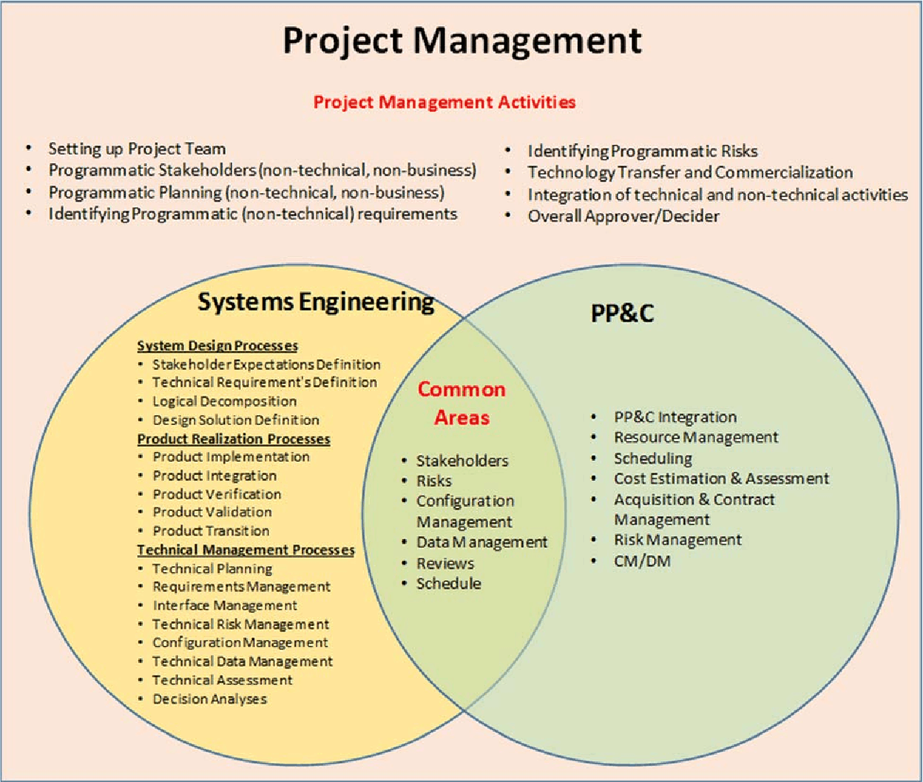
Figure 2.0-1 SE in Context of Overall Project Management
- Expanded Guidance on Systems Engineering (Volume 2) at NASA, Volume 2: Crosscutting Topics, Special Topics, and Appendices (March 2016) 272 pages
Historically, most successful NASA projects have depended on effectively blending project management, systems engineering, and technical expertise among NASA, contractors, and third parties. Underlying these successes are a variety of agreements (e.g., contract, memorandum of understanding, grant, cooperative agreement) between NASA organizations or between NASA and other Government agencies, Government organizations, companies, universities, research laboratories, and so on. To simplify the discussions, the term “contract” is used to encompass these agreements. This section focuses on the NASA systems engineering activities pertinent to awarding a contract, managing contract performance, and completing a contract. In particular, NASA systems engineering interfaces to the procurement process are covered, since the NASA engineering technical team plays a key role in the development and evaluation of contract documentation. Contractors and third parties perform activities that supplement (or substitute for) the NASA project technical team accomplishment of the NASA common systems engineering technical process activities and requirements outlined in this guide. Since contractors might be involved in any part of the systems engineering life cycle, the NASA project technical team needs to know how to prepare for, allocate or perform, and implement surveillance of technical activities that are allocated to contractors.
Authors
Hirshorn, Steven R. (NASA Headquarters Washington, DC United States)
Publication Date
March 16, 2017
Report/Patent Number
NASA/SP-2016-6105/SUPPL/Vol 2
HQ-E-DAA-TN42999
Distribution Limits
Public
Available Downloads
Related Records
See Also NASA Systems Engineering Handbook
See Also Expanded Guidance for NASA Systems Engineering. volume 1: Systems Engineering Practices
6.0 Crosscutting Topics
The topics in this chapter cut across all life-cycle phases and are of special interest for enhancing the performance of the systems engineering process or constitute special considerations in the performance of systems engineering. These topics include the following:
Engineering with contracts: applying systems engineering principles to contracting and contractors;
Concurrent engineering methods: diverse specialists systematically collaborating simultaneously in a shared environment, real or virtual, to yield an integrated design;
Selecting engineering design tools: integrated design facilities and tools;
Environmental, nuclear safety, and planetary protection policy compliance: protecting the environment and discussing the importance of the Nation’s space assets;
Use of the metric system;
Systems engineering on multi-level/multi-phase programs and projects: special considerations;
Fault management: understanding and managing the off-nominal system behaviors;
Technical margins: establishing and managing for contingencies to reduce development risk and increase the chance for mission success; and
Human systems integration: balancing total system safety and effectiveness to ensure mission success.
6.1.2 Acquisition Strategy
While this section pertains to projects where the decision has already been made to have a contractor implement a portion of the project, it is important to remember that the choice between “making” a product in-house by NASA and “buying” it from a contractor is one of the most crucial decisions in systems development.
7.0 Special Topics
The articles in this chapter represent topics that are of special interest, may be relatively new to the Agency or may be new methods that can provide benefit. These topics represent useful approaches to system engineering and the sections below provide information on the application of statistical engineering and Model-Based System Engineering (MBSE) on programs, projects, or activities. As these topics are still emerging in their forms and applications within the Agency, there exists flexibility in how to apply these methods to a particular program, project, or activity. In today’s computer-based, data-rich world, the systems engineer needs to deal with statistical information and model-based engineering approaches employed by various engineering disciplines. The extent to which statistical engineering and MBSE are applied depends on the judgment of the systems engineer about the benefits to technical, schedule, and cost performance that these approaches provide. The systems engineer should also consider the organizational effects of applying these methods including efficiency and the organization’s cultural acceptance.
“MBSE is part of a long-term trend toward model-centric approaches adopted by other engineering disciplines, including mechanical, electrical and software. In particular, MBSE is expected to replace the document-centric approach that has been practiced by systems engineers in the past and to influence the future practice of systems engineering by being fully integrated into the definition of systems engineering processes.” (Source: INCOSE 2007)
7.2.7 MBSE Benefits
Model-based systems engineering will enable the opportunity for overall better quality, lower cost, and lower risk for several reasons. These benefits come about because:
There can be greater consistency of all products because any single piece of design information can be expressed authoritatively in a single place that can later be referred to by others for decisions, derivations, or formation of artifacts.
There can be better visibility into the salient characteristics of a system because multiple views can be created that succinctly address specific stakeholder concerns.
There can be greater congruence between documentation and reality: Model-based artifacts can be generated automatically, lowering the effort to keep them up to date with the result that artifacts can always match the best available information.
Navigation, traceability, and interrogation of information are facilitated in the model-based approach. People can have access to the information they are authorized to have more quickly and on an as-needed basis without going through manual distribution or search processes.
Models used for verification can have higher quality, and provide greater confidence if design and manufacturing models are applied diligently before and after use of the verification models.
Models themselves can help to reveal hidden flaws of the models.
There can be less investment lost in erroneous design because sometimes the model reveals a flaw as soon as it is created, enabling correction before downstream work is done, work that would be invalid if the upstream mistake were not corrected immediately.
Having fewer inconsistencies between artifacts lowers the costs for verification.
It provides identification, management, interoperability, and integration of information across business or organizational elements needed to support program PDLM goals.
It ensures that data needed by programs and projects (e.g., for milestones, reviews, mission operations, and anomalies or investigations, decisions, and outcomes) are identified and managed to provide traceability of the data used in decision-making.
7.3 Concept Maturity Levels
Concept Maturity Levels (CMLs) were introduced to provide mission architects and systems engineers with a way to measure and communicate the fidelity and accuracy of a mission concept during the early stages of its life cycle. The CMLs represent a scale that provides a repeatable way to assess and describe the maturity of concepts and a single numerical scale, comparable to the TRL scale, to assess the maturity of different mission concepts. Mission concept development teams use this method and associated tools throughout the pre-project study phase and on through the Formulation phases (Phase A/B). Prior to the advent of the CML scale, there were no standardized methods available to (1) determine how much work was placed into a mission concept; (2) explicitly know when in a pre-project’s life-cycle trade space exploration would be most advantageous to ensuring that a mission concept was the most scientifically relevant and cost-effective; (3) determine which concepts had the same level of work and could be compared on the same terms; and (4) how much work a mission concept required to achieve a subsequent level of maturity.
Appendix A: Acronyms
Appendix B: Glossary
Appendix C: How to Write a Good Requirement – Checklist
Appendix D: Requirements Verification Matrix
Appendix E: Creating the Validation Plan with a Validation Requirements Matrix
Appendix F: Functional, Timing, and State Analysis
Appendix G: Technology Assessment / Insertion
Appendix H: Integration Plan Outline
Appendix I: Verification and Validation Plan Outline
Appendix J: SEMP Content Outline
Appendix K: Technical Plans
Appendix L: Interface Requirements Document Outline
Appendix M: CM Plan Outline
Appendix N: Guidance on Technical Peer Reviews/Inspections
Appendix O: Reserved
Appendix P: SOW Review Checklist
Appendix Q: Reserved
Appendix R: HSI Plan Content Outline
Appendix S: Concept of Operations Annotated Outline
Appendix T: Systems Engineering in Phase E (Operations and Sustainment)
T.1 Overview.
In general, normal Phase E activities reflect a reduced emphasis on system design processes but a continued focus on product realization and technical management. Product realization process execution in Phase E takes the form of continued mission plan generation (and update), response to changing flight conditions (and occurrence of in-flight anomalies), and update of mission operations techniques, procedures, and guidelines based on operational experience gained. Technical management processes ensure that appropriate rigor and risk management practices are applied in the execution of the product realization processes. Successful Phase E execution requires the prior establishment of mission operations capabilities in four (4) distinct categories: tools, processes, products, and trained personnel. These capabilities may be developed as separate entities, but need to be fused together in Phase E to form an end-to-end operational capability. Although systems engineering activities and processes are constrained throughout the entire project life cycle, additional pressures exist in Phase E:
Increased resource constraints – Even when additional funding or staffing can be secured, building new capabilities or training new personnel may require more time or effort than is available. Project budget and staffing profiles generally decrease at or before entry into Phase E, and the remaining personnel are typically focused on mission execution.
Unforgiving schedule – Unlike pre-flight test activities, it may be difficult or even impossible to pause mission execution to deal with technical issues of a spacecraft in operation. It is typically difficult or impossible to truly pause mission execution after launch. These factors must be addressed when considering activities that introduce change and risk during Phase E.
3.1 Leading the Transformation of Model-based Engineering
by
Al Hoheb
Enterprise Transformation Leader
The Aerospace Corporation
A Federally Funded Research Corporation (FFRC)
(Notes provided by Ralph Young, Editor, PPI SyEN)
Al Hoheb presented an INCOSE Tutorial (Webinar) on August 19, 2020, “Leading the Transformation of Model-based Engineering”. Al is the author of the INCOSE documentation, INCOSE Model-based Capabilities Matrix and Users Guide (available at the INCOSE Website – see below).
Following are some of the key points that were emphasized in this briefing.
- It’s important for the leader to discern that the purpose and objectives of the organization’s modeling efforts are derived from strategic plans. Engaging internal and external stakeholders to agree on modeling objectives in itself is a useful document that is typically incorporated into a Digital Engineering/Model Implementation Plan or CONOPS encompassing the life cycle and characterizes the stages of modeling capability development.
- The model-based implementation approach involves:
- Determining the vision and goals of the modeling effort.
- Determining the enterprise modeling objectives based on the organizational goals, objectives, and strategy.
- Defining the modeling objectives to target the needed modeling capabilities.
- Defining the modeling elements and data necessary to meet modeling objectives.
A series of workshops should be used to evolve the information for the Model-based Capabilities Matrix (MBCM).
- Develop a top-level strategy involving stakeholders.
- Use the INCOSE Model-based Objectives Matrix (an Excel file available to members of INCOSE at no charge from the INCOSE Store). A set of 42 unique and necessary capabilities, each with a “name”, has been identified.
- They are provided as an Excel spreadsheet.
- The approach should be tailored to the organization’s needs – provide a tab that describes the organization’s desired capabilities.
- For each capability, characterize the current stage of development (0 through 4), both current and desired.
- One can use either of two capability views: the OSD DE Strategy view or the role-based view. The DE Strategy view provides is most useful to show compliance with the strategy. Al suggests that the role-based view is best for most organizations, because roles are familiar, and then the capabilities development can be allocated to roles.
- The Capability Matrix Excel file has tabs to view and print the descriptions of the 42 capabilities. Al advises that special attention should be given to the “Model Management” capability in order to clarify the model situation in the organization for all stakeholders. On most assessments this is rated as “ad hoc” indicating that models within an organization are inadequately managed.
- Positive outcomes have been achieved in using this approach with more than eight major U. S. Government organizations. The approach:
- Improves communications across the organization;
- Makes people aware of all of the capabilities that are needed;
- Is facilitated by using workshops to roll out the approach in an organization;
- Includes several examples of Use Cases:
- Strategic vision.
- Provide a roadmap.
- Provide a yardstick to characterize various capabilities.
- Tactical planning.
- Program review.
- Qualify bidders.
- Source selection (acquisitions selection and determination of drivers).
- Enhance processes.
- Determination of the resources required to evolve modeling capabilities.
- Guide preparation of many enterprise and program documents.
Al shared feedback from a user of the MBCM approach:
“Using the Model Based Capabilities Matrix (MBCM) helped my organization understand what we needed to do and that the cost was worth it.”
Questions often posed include the following:
- How do organizations get started?
- Define potential DE/MBSE benefits as a set of DE/Modeling objectives.
- Define the DE/Modeling Strategy. The Digital Engineering (DE) Strategy Accelerators – Benefits and Approach ATR-2020-01688, identify Problem Framing, the MBCA, and identification of Modeling Elements and Data, through three short, linked workshops as essential to defining a DE/Modeling strategy. These lead to plans and roadmaps.
- Define the DE/Modeling enabled processes and plans. ATR-2016-02402 Rev A – Model-Based Systems Engineering Guidance for Government Acquired Programs.
- Perform a free on-line MBCA (available at aerospace.com/mbca)
- to gather information on current state and needed state. It takes one person about three hours to do this and to generate MBCA reports that one can edit and use.
- Apply lessons learned/best practices from an engineering and program management standpoint.
- ATR-2016-02309 – Lessons Learned and Recommended Best Practices from Model-Based Systems Engineering (MBSE) Pilot Projects
- OTR-2019-00913 – Top 6 Things Leaders can Do to Drive MBSE
- What examples can be provided to help the organization after the assessment?
Following are concepts that most organizations need:
-
- DE Implementation strategy, plan, objectives
- Identify DE enabled processes
- Identify DE features
- Identify guides and standards
- Model Project Management Guide (draft) – TOR-2020-01577
- Other guides
- Data exchange standards
- Identify Integrated data environment
- Multi Tools Integration and Test Environment (MTITE) Study – TOR-2020-01553 (US Gov’t only)
Access the INCOSE Briefing (INCOSE Member Login; then search for INCOSE Webinar 142)
Download
INCOSE Model-Based Capabilities Matrix and User Guide (Excel file and PDF file, respectively) (Prepared by Joe Hale and Al Hoheb) (753 KB)
3.2 Three Ways to Simplify Complex Projects
by
Dave Wakeman
My mind has been so focused lately on the leadership failures we’ve seen during the pandemic that I often forget to think about ways that we can help our project teams move forward right now. That got me to thinking about something we often struggle within any situation: simplification.
I imagine most of us feel like we’re managing teams of complex individuals working on complex projects, with answers and solutions that are also complex. If you catch me at the right time, I’ll tell you everything is complex.
Over the years, one thing I’ve learned that adds value—for all my stakeholders—is the ability to take the complex and make it simple.
Case in point: A friend of mine asked me about a branding project his organization was focused on. He asked if I could sprinkle some of the “Dave three-point simplification” on his marketing challenge. I joke, but the ability to simplify projects and decisions for our team members can help steer us towards success—if we do it well.
Here are three points to keep in mind:
1. Focus on the essential.
When we’re working on something, we can go down the rabbit hole pretty quickly, running through all of the minor details, dead ends and roundabout ideas that don’t actually matter.
To be fair, most of us and our team members have a lot of knowledge, and we want to share our relevant experiences. But in many cases, we allow this abundance of knowledge to get in the way of just focusing on the key ideas or tasks. Instead, think through the essential details, actions or points that need to be made. And stick to those.
2. Cut the lingo.
I’m sure you’ve experienced this: people using a crazy language of acronyms, shorthand and code that only makes sense to those within the field. Even if they’re confused, a lot of folks don’t want to speak up and say, “Hey, what does this jumble of alphabet soup and buzzwords mean?”
To make sure we’re getting our points across, we have to step back and focus on using simple and clear language—even if it might seem too basic. When you’re talking and sharing instructions or feedback with a stakeholder, don’t assume they understand every definition, acronym or idea familiar to you.
Take the time to define concepts, frame ideas and make sure the point you’re making is getting through—even if you sound like a first-year business student.
3. Lean on visuals and metaphors.
When we’re focusing on simplifying a topic, we need to consider the fact that everyone learns in a different way. Some folks like to learn by reading, others by listening or through imagery. And in most cases, learning is aided by actually doing something. So as you’re working on simplifying and coaching your team, don’t be afraid to use visuals or metaphors that draw distinctions or illustrate your point in a different way to help others better understand the information.
For me, simplification is a great tool. And even though I know I don’t always get it right, I’d still much rather be known for talking at too basic of a level than as an out-of-touch bore.
3.3 The Test Like You Fly (TLYF) Process – Creating Operationally Realistic Tests and finding Mission Critical Faults Before It’s Too Late.
Julie White
The Aerospace Corporation
Presentation to the INCOSE Los Angeles Chapter
August 11, 2020
Abstract
Test Like You Fly. Test As You Fly. Test Like You Operate. Test Like You Intend to Use the System. The concept may be up to 500 years old, as something equivalent was used by the British Navy in the early 1500s when heavy cannons started to be mounted on ships for broadside attacks. Naval engineers used this approach to testing to ensure that the new technology worked as intended in the modified heritage sailing vessels before committing them to battle. Test Like You Fly (TLYF) has been part of aviation development, especially for the use of planes as weapons systems. This terminology, sometimes known as “Test As You Fly” in NASA parlance, worked its way into space systems development, probably in the late 1970s or early 1980s. However, the usage was fairly loose, meaning different things to different people.
The “Test Like You Fly” (TLYF) Process, developed by a government/industry team in 2007 – 2010, is based on an approach that is broader than “test.” We have come to define it as a pre-launch/pre-operational systems engineering process that translates mission operations concepts into operationally realistic tests intended to detect latent mission critical flaws that can only be revealed when used as it would be in use. The process incorporates a “pre-mortem” fault analysis to better understand how the mission could fail and use that insight to craft tests to flush out those flaws. The process also includes fault-informed risk management to account for un-exonerated flaw paths to mission failure.
The short introduction to the TLYF Process highlights the space mission failures that led us to this process, a short explanation of the process methods, and some non-space conceptual applications of the process.
About Julie White
Julie White has been with The Aerospace Corporation for over 45 years. She is currently a senior project leader in the Systems Integration & Test Office (SITO) of the Systems Engineering Division. She has extensive experience with requirements analysis, integration, test, and operations. She has helped architect “like you fly” “days in the life” tests for four USAF Space Test Program one-of-a-kind R&D missions. She spent time analyzing trends and the engineering implications of serious and fatal on-orbit satellite anomalies that occurred over a 30-year period worldwide. The large number of serious anomalies whose escapes could have been prevented by consistent implementation of TLYF techniques was the motivation for creating a TLYF assessment and execution process.
She was a contributor to the 1st edition of the Space Vehicle Test and Evaluation Handbook (The Aerospace Corporation, 2006) and senior editor and contributor for the 2nd edition of this book (The Aerospace Corporation, 2011). She has written and presented several international papers on the TLYF Process, as well as others on risk management, mission development, satellite End-of-Life trends, and other on-orbit mission results. She holds a Bachelor’s degree in Physics and Astronomy from the University of Maryland, College Park, MD (USA), and a Master’s degree in Astronomy from the University of Massachusetts, Amherst.
4. SYstems Engineering News
4.1 INCOSE’s Chapter Circle Awards for 2019 (Awarded in 2020)
by
Tony Williams, INCOSE Americas Sector Director
Lucio Tirone, INCOSE Europe, Middle East and Africa Sector Director
Serge Landry, INCOSE Asia and Oceania Sector Director
INCOSE’s Circle Awards Program recognizes Chapters for excellence in providing services to their membership. These awards are an effective way to exchange best practices among Chapters, and they enable Chapters to monitor their own performance year after year, providing continuous improvement in delivering value to their members and stakeholders.
Chapters document their activities throughout the year on a scoresheet, which includes topics including Officer Training, Chapter Planning, Events, Communications, Membership, Technical Engagement, Outreach & Collaboration, INCOSE Support, Operations, and Local Recognition. The scoresheet is reviewed by a committee of dedicated volunteers in January of the following year. The scoring committee validates the experience for each Chapter and then assigns award levels.
The initial entry level for the Circle Awards is the Bronze level, which recognizes Chapters that have great performance in a few areas across various topics. This year’s winners at the Bronze level are Atlanta and Great Plains (which includes members from across Oklahoma and Kansas).

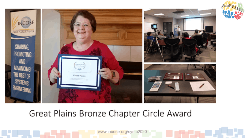
Bronze Circle Award Winners: Atlanta and Great Plains Chapter
Silver circle awards for 2019 include Cleveland-Northern Ohio, Denmark, Finger Lakes (which is in upstate New York), Hampton Roads (which is in Southern Virginia), Huntsville, Italia, North Texas, Southern Maryland, and Wasatch (which is in Utah).

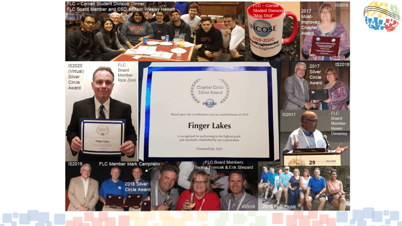


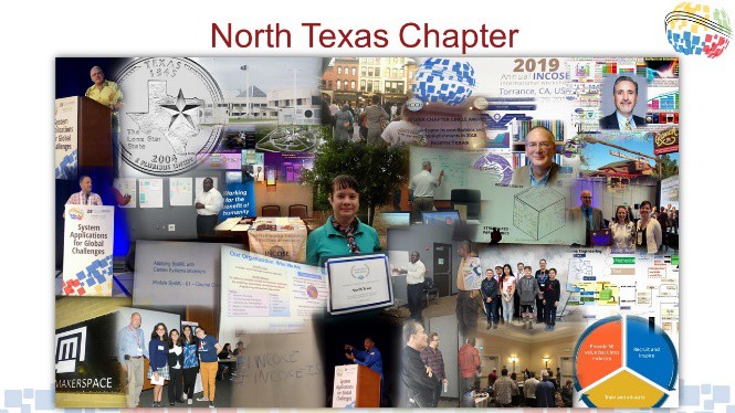
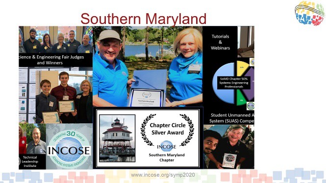
![]()
Silver Circle Award Winners: Denmark, Finger Lakes, Hampton Roads, Huntsville, Italia, North Texas, Southern Maryland, and Wasatch
The Gold Circle awards acknowledge very high standards of consistent achievement across all the Circle Award categories. The Gold Circle Award winning chapters this this year are India, Israel, and the Washington Metro Area.
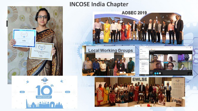
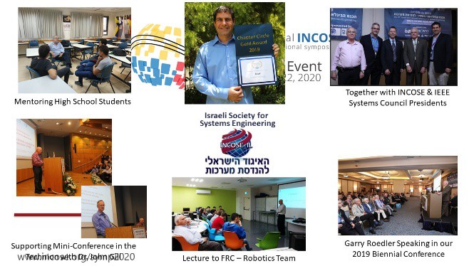
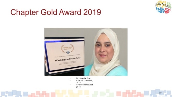
Gold Circle Award Winners: India, Israel, and Washington Metro Area
The highest level of Circle Award is the Platinum level. The Platinum Circle Award recognizes chapters that are really knocking it out of the park across all scoring categories. When you look at the Circle Awards Score Sheet, you’ll quickly see that the only way to win at this level is to perform excellently across all categories, including Officer Training, Chapter Planning, Events, Communications, Membership, Technical Engagement, Outreach & Collaboration, INCOSE Support, Operations, and Local Recognition. This year’s winners for the Platinum Circle Award are Chesapeake, Chicagoland, Enchantment (which is in New Mexico), Los Angeles, North Star (which serves the Minnesota, Wisconsin, and nearby areas), and San Diego.
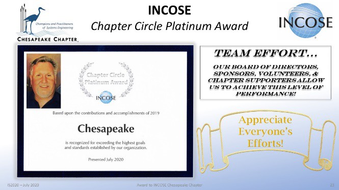
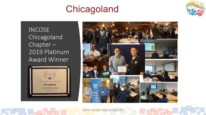
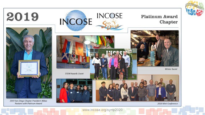
Platinum Circle Award Winners: Chesapeake, Chicagoland, Enchantment, Los Angeles, North Star, and San Diego
In addition to the recognition that Chapters receive for achieving a certain level of performance, the Circle Awards include two special awards: The Director’s Award for the most improved chapter and the President’s Award for the most outstanding chapter.
This year the Director’s Award for the most improved Chapter goes to India. India had an outstanding year, including organizing a large conference, and conducting many local events, webinars, and a workshop for Empowering Women Leaders in Systems Engineering (EWLSE).
The President’s Award, which recognizes the Chapter providing the most singular outstanding service to its membership, was awarded to the Chesapeake Chapter. We congratulate the Chesapeake Chapter for its continued success. Chesapeake has always been an outstanding Chapter, and continues to perform at an amazing level. One example of the outstanding services that the Chesapeake Chapter provides is that each summer, the Chapter sponsors an event at which they invite all the Systems Engineering Professionals (SEPs) in the region and recognize newly certified SEPs.
President’s Award Winner: Chesapeake
While not part of the Circle Awards, each year the Chapter Presidents have the ability to nominate another chapter for the Good Neighbor award, which recognizes Chapters that have gone above and beyond and are reaching out to help another Chapter succeed. For the Americas, we have two winners of the Good Neighbor Award: North Star and Chicagoland, who are being recognized for their service to support the restart of the Heartland Chapter. For Europe, Middle East, and Africa, the Good Neighbor Award goes to Spain.


Good Neighbor Award Winners – Chicagoland and North Star (Americas), Spain (EMEA)
The Circle Awards acknowledge Chapters for their efforts in delivering great services to members and stakeholders and facilitating yearly planning.
Congratulations to all of the winners!
4.2 Relying on Innovation – Site Reliability Engineering (SRE)
“SRE enables development teams to deploy faster, while using any failures to improve the overall health of the system.”
10 August 2020
Source: Bluenotes.anz.com
Innovation is incremental or radical improvements to solve customer problems. And what do customers want, arguably more than anything else? Reliability. They want products and services that deliver on service level agreements. So, it stands to reason reliability is an important prerequisite to innovation. Unfortunately, reliability is not all that easy to achieve. In highly competitive markets where service is key differentiator, there is one practice in particular growing in popularity around the world: site reliability engineering (SRE).
What is it?
“Some things benefit from shocks; they thrive and grow when exposed to volatility, randomness, disorder, and stressors and love adventure, risk, and uncertainty. Yet, in spite of the ubiquity of the phenomenon, there is no word for the exact opposite of fragile. Let us call it antifragile.
Antifragility is beyond resilience or robustness. The resilient resists shocks and stays the same; the antifragile gets better.”
– Nassim Nicholas Taleb
Stemming from Nassim Nicholas Taleb’s concept of “antifragility”, at its core, SRE involves creating systems that learn from the errors and outages that inevitably arise. It helps turn massive, complex and fragile enterprise systems into “antifragile” ones that can meet dynamic challenges.
There is confusion around what SRE means in practice, similar to when DevOps first arrived on the scene. It’s perhaps best described by Ben Treynor, the Senior Vice President overseeing technical operations at Google – and originator of the term – who famously said SRE is “what happens when you ask a software engineer to design an operations team”.
One key issue SRE exists to solve is organizational silos, particularly between development and operations teams. A site reliability engineer’s job is to balance the development of new features while ensuring production systems run smoothly and reliably. SRE enables development teams to deploy faster, while using any failures to improve the overall health of the system.
Another key issue is value add metrics. You manage what you measure. So careful consideration is given to service level indicators (SLIs), metrics used to measure service performance, such as latency or error rate. This is vitally important as it forces the team to consider how to measure performance in a way that directly correlates to customer service level agreements (SLAs).
Increasing popularity
ANZ, Atlassian and, of course, Google, are just some of the businesses in Australia that have embraced SRE. While still a nascent field, SRE is rapidly increasing in popularity in enterprise organizations with many dipping their toes in the SRE pool.
There are several key principles of SRE that make it so effective.
First, SRE is driven by an appreciation for using errors and the metrics those errors produce to relentlessly improve the health of IT systems. It uses data to assess and report on the reliability and availability of systems at every stage of the development cycle to determine if changes are hurting or helping the business.
At the end of the day, business leaders care about SLAs with the customer, while technologists are all about SLIs. SRE forges a valuable link between these two, translating a site reliability engineer’s work into something that not only the business can understand but is also extremely valuable to ensuring SLAs are met. SLIs and SLAs are linked by service level objectives (SLOs), which are measurements of the performance of some aspect of the application, service or platform.
The IT infrastructure library (ITIL) framework and IT service management (ITSM) have struggled to find their place in the modern world of cloud computing and a DevOps culture. What many still fail to understand is that ITIL and most importantly ITSM, are at the heart and core of SRE practices.
Not without challenges
While adoption of SRE is growing in Australia, organizations that succeed at it are few and far between. There are several reasons for this.
The first is because SRE requires cultural and organizational transformation before it can be adopted successfully. This might include the formation of cross-functional teams to break down silos, the transition to a cloud operating model and the need for different skills within the business such as engineers who understand the full lifecycle of software development and deployment.
This is easier said than done. Australia has a significant shortage of technology talent, with the Australian Computer Society estimating an additional 100,000 workers will be needed by 2024.
The unfortunate reality is Australia bleeds home-grown tech talent to markets like the US where the opportunities in the industry are immense, with the cream of the crop that remain in the country often opting to work for tech giants like Google, Microsoft and Facebook.
I experienced the pitfalls of this firsthand while executive manager for operations for the advanced analytics and automated decisioning area at a big four bank in Australia (not ANZ!). Software developers and operations engineers have very unique skill sets. It’s incredibly difficult to transform software developers to be more operations-minded, and operations engineers to be more development-minded.
Then there’s the challenge of executive buy-in. Even if business leaders understand SRE, many are taken aback by the cost of introducing more automation and managing legacy infrastructure with years of capitalized costs, especially as many are grappling with the economic fallout from COVID-19.
Finally, there’s a clear divide between adoption and successful adoption. In my experience, a lot of companies are reading SRE handbooks and going out on their own. As a result, they’re not successfully implementing SRE practices, which then leads to not getting executive buy-in to continue down this path.
Core business need
If World War III broke out and you wanted to check the internet was still operational, chances are you’d turn to Google. Why? Because Google is reliable. The tech giant realized early on the prerequisite to success and innovation is reliability. And look where it’s gotten the business.
In business IT, there are a million different ways things can go wrong. Enterprises need to be thinking less like a business-business and more like a tech-business because, in a market of fragile competition, SRE is increasingly becoming a key differentiator.
The author, Michael Ewald, is Director of Engineering and Consulting for APAC at Contino
4.3 National Science Foundation (USA) Invests $104 Million to Launch Four New Engineering Research Centers

The National Science Foundation (USA) has announced awards totaling $104 million to create four new Engineering Research Centers (ERCs). The new centers, each with several leading American research universities collaborating as partners, will receive $26 million each for an initial five-year period. They will focus on:
Preserving biological systems, including cells, tissues, organs and whole organisms;
Designing a sustainable infrastructure for electrified vehicles;
Creating new technologies to build the capacity of the quantum internet; and
Advancing precision agriculture by promoting food, energy and water security and minimizing resource use and environmental impacts of agricultural practices.
4.4 These Four Skills can make the World Better after COVID-19
by
Alumni of the 5th Edition of the Master in Strategic Foresight
Universitå Degli Studi Di Trento

- To handle the aftermath of COVID-19 and tackle the world’s biggest issues, we need to change the way we make decisions and become more knowledgeable about the future;
- A systemic analysis of the impact of COVID-19 in Italy highlights four skills required to face our complex world: future literacy, anticipation, systems thinking and strategic foresight are increasingly essential skills.
The pandemic is first and foremost a human tragedy, but it is also shaking the pillars on which our society is based.
This shock to the planet has built an expectation of big changes that will lead us to a different and hopefully better world. But how should we get ready for these changes? Where should we intervene and with which priorities? What are the opportunities that we must seize and the risks to mitigate?
In order for the hope of a better world to move beyond rhetorical optimism, we must be able to answer these questions. We must change the way we make decisions and become more knowledgeable about the future. Conventional approaches are no longer sufficient; new skills are needed.
But what are these new skills? I (author) and seven friends, all alumni of the Università di Trento’s Strategic Foresight MA degree, decided to use our expertise and the power of our collective intelligence to build a systemic analysis of the impact of COVID-19 in Italy. It was a challenging team exercise conducted remotely as we were all confined at home. The results of this analysis allowed us to picture the outlines of this phenomena and explain which new skills are needed to face this complexity and how to practice them.
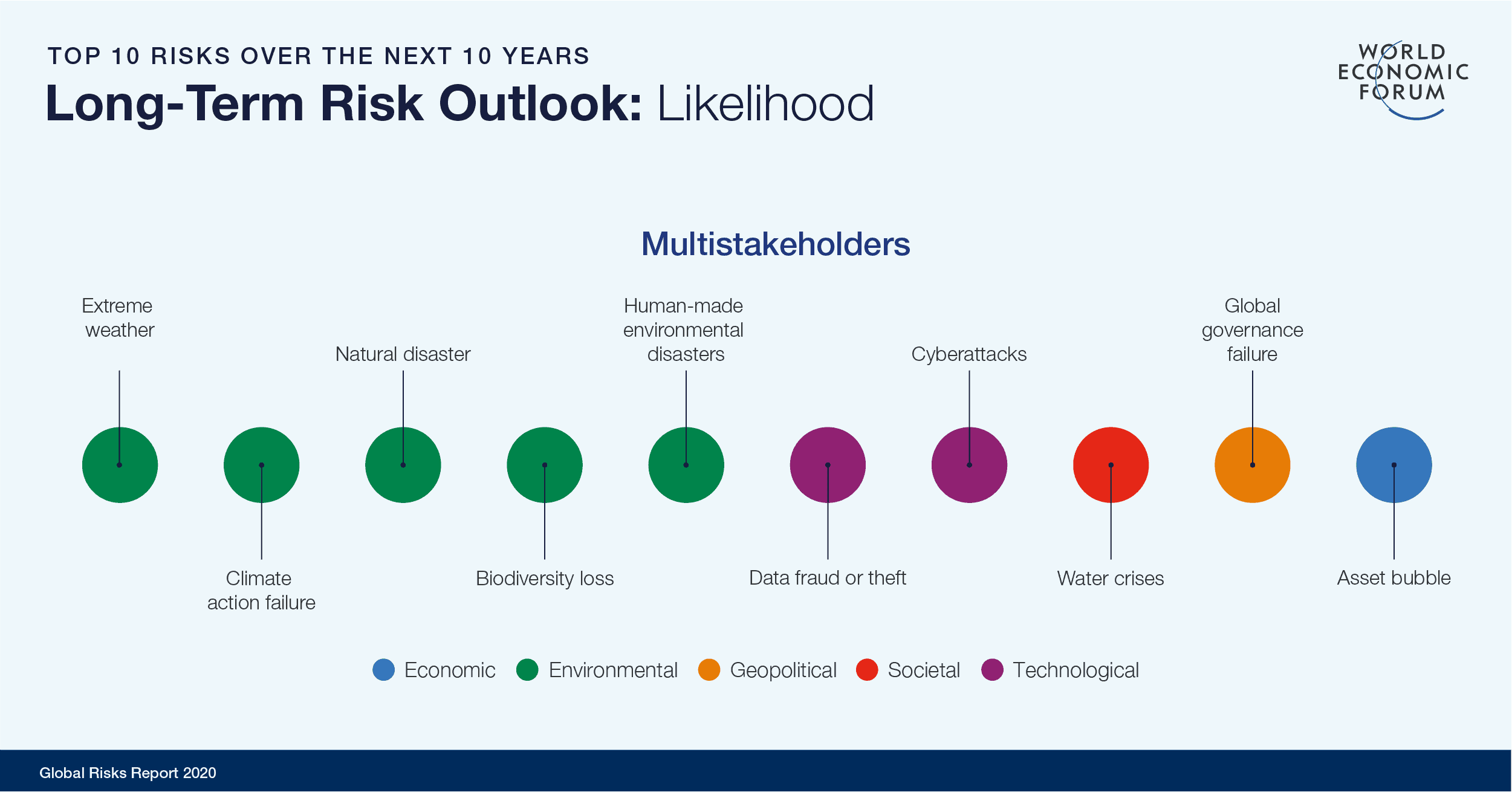
The Global Risks Report 2020
Image: World Economic Forum
Skill 1: Future Literacy
In general terms, literacy is simply the ability to read and write, although it may be intended with a broader and more insightful meaning. The significant increase of literacy across many countries in the last two centuries together with the push of industrial revolutions has enabled a dramatic leap forward for civilization.
Now, however, we are living in a new era where the world is changing faster than ever and any change may have huge global consequences because we are increasingly connected to each other.
Perhaps it is time our society takes another step forward to cope with this new challenge, becoming a more “future literate” society. This is the skill that allows people to better imagine and make sense of the future. It’s important because it is images of the future that drive our expectations, disappointments and willingness to invest or change.
UNESCO is building future literacy globally with local actors in more than 20 countries who organize Future Labs in schools and communities. The goal is to demonstrate that imagining the future is something that’s accessible to everybody and that this capacity to imagine can be improved.
In December 2019 in Paris, UNESCO held the first Global Futures Literacy Design Forum with 28 different laboratories and people from all over the world. In Brazil, the recently launched #freethefuture movement is also pushing future literacy.
The question here is not to think of the future as an add-on; it should be integrated, like reading and writing, with what we do and what we think.
Skill 2: Systems Thinking
Almost all the challenges presented by the effects of COVID-19 relate to “systems”. Essentially a system consists of three things: a scope or function, parts and relationships. In a system the effect of interventions may appear distant in space and time.
Systems thinking is a mindset to think, communicate and learn about systems to make the full patterns clearer, improve and share the understanding of problems and see how to face them effectively.
In our exercise, through a method named “Futures Wheel”, we built a systemic picture of the COVID-19 pandemic in Italy, exploring its impact on different areas: social, technological, economic, environmental and political. This was the magnifying glass which allowed us to spot the strategic themes that need to be faced.
Skill 3: Anticipation
To explain this concept, we should reflect on a couple of things: in the present, there are signals of the future; and these signals are of something that is not yet evident but which has the potential to become empirical evidence if circumstances permit. Therefore, today there are futures in progress even if they are not clearly visible for most of us.
The anticipation skill requires us to learn how to recognize these possible futures and to use this augmented consciousness to shape our decisions and actions in the present.
This in practice means modifying our habits and behaviors to be better prepared for a continuously changing world.
Skill 4: Strategic Foresight
The disruptive changes in front of us will require choices and decisions and these will influence how the future world will evolve.
But how do we set our helm to first survive and then, hopefully, take advantage of the opportunities in this rough sea of change? This is a big challenge that requires a new strategic thinking attitude for governments, businesses, organizations and people to better understand change and the future, as we will all be living and working in a future world that’s different from today in significant ways.
Strategic foresight and more generally “Futures Studies” are the disciplines that have broadened to an exploration of alternative futures and deepened to investigate the worldviews that underlie possible, plausible, probable and preferred futures.
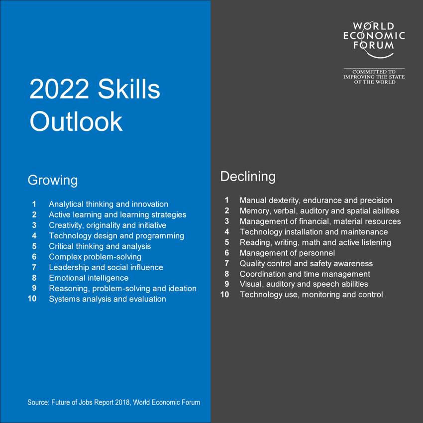
What skills will be in demand in 2022?
Image: Future of Jobs Report 2018, World Economic Forum
Moving from the assumption that the future will be a continuity of the present toward a better understanding of changes and multiplicity of the future will allow us to develop future-proof strategies that anticipate the consequences of alternative futures.
Ultimately, what we need is a cultural leap from a reactive approach to an anticipatory one. But we believe that this will only be possible if we manage to embed the competencies mentioned above into the skill sets of leaders, policy-makers, teachers and every individual.
Today, we may grab the great chance for a breakthrough which could bring us to a better world, a more inclusive one with a sustainable economic system, an increased maturity of our society and more conscious electors. A world where countries cooperate to make people safer, happier and healthier and to treat them as equals.
Download the Article here
4.5 An INCOSE Team is Addressing Heuristics
An INCOSE Team provided an initial progress report to the INCOSE Fellows at the virtual INCOSE International Symposium 2020. Feedback was requested and provided that will guide continuing efforts to shape future plans, especially issues for resolution in moving ahead. A “Foundation Document” has been developed by the Heuristics Team. Current intentions for the efforts of the Team include:
- A set of heuristics, readily available to all practicing systems engineers.
- Regularly referenced by individual systems engineers and non-systems engineers, updated and maintained, as relevant, by INCOSE.
- Complementing the SE Principles (under development by another FuSE WG).
- Supporting the challenges identified by INCOSE FuSE Future SE Heuristics team program.
- Constructed using plain, well understood, English so that both systems engineers and non-systems engineers can easily understand.
The focus has been on heuristics which address newer SE challenges such as complex adaptive systems (in order to not duplicate c’s efforts).
Please provide your feedback to dorothy.mckinney@icloud.com
4.6 IT Modernization is Evolving. It’s Time to Take another Look
Over half a century ago mainframe COBOL helped send men to the moon. Since then it has been used to develop and operate a myriad of government systems. It is so prevalent that currently, 75% of the world’s financial transactions are processed though COBOL systems, according to Chris Ostrander, principal at Deloitte Consulting LLP. Many organizations in the public and private sector have tried to modernize their COBOL systems and failed, while others have hesitated to even attempt it, as it runs the heart of their business. The current global pandemic has caused COBOL to again dominate headlines given the sudden surge of demand for access to the services it enables. How can federal government agencies, still working with the once-state-of-the-art language of COBOL, use inspiration from Neil Armstrong, to take one small step towards modernization, one giant leap toward next generation systems?
Thinking Differently About Modernization
“The technologies and approaches people think they know have evolved,” said Scott Buchholz, managing director and chief technology officer for Government and Public Services at Deloitte Consulting LLP. “People who have been down the journey once might want to take another look.”
In decades past, systems modernization projects often started by gathering user requirements based on their understanding of current processes and operations. Technology modernization specialists, like Scott, would create bespoke upgrades based solely on the requirements provided, and, once modernized, hand the new system back to users for testing. But users kept finding problems. It inevitably turned out that the users who had been providing the requirements did not have a full view of how the system worked, and successfully redeveloping the system actually required an understanding of all individual parts, along with a larger holistic view of how the parts worked together.
Similar to NASA realizing that COBOL, originally a necessity for launch, needed to progress into the future, CIOs also began realizing their IT systems strategies needed to make significant technological leaps, possibly leaving COBOL behind. In the last decade alone, IT Modernization trends have included:
- Understanding legacy system functionality using automated tools
- Speeding up development and system integration with Low Code Platforms
- Using Cloud to standardize platforms and reduce time to market
Helping understand legacy system functionality with automated tools
The risk of legacy modernization project failure often increases if there is not a complete understanding of scope, scale, and details of the legacy functionality they are attempting to replace.
“You can think about most legacy systems like the attic in my grandmother’s old barn – a dangerous treasure trove with sharp, rusty objects everywhere,” Buchholz said. “Picking anything up meant picking up a pile of stuff, and nobody really knew what was underneath.”
Increasingly powerful code and data analysis tools automate a large portion of a formerly manual process to understand a system’s business logic and the data it uses, providing valuable information into a strategic approach for the organization to modernize while still functioning with business-as-usual.
Speeding up development and system integration with Low Code Platforms
For years, government agencies like NASA had a saying, “slow COBOL is still better than no COBOL.” Recently though, NASA and other organizations began to look at how legacy mainframes that once got them to the moon could now be transformed through automated tools. Tools such as low code platforms could accelerate processes, while at the same time reducing costs to get the new functionality up and running. Updating a myriad of interfaces to a legacy system happens to be something low-code systems excel at, as they can quickly build APIs and replace piles of file-based legacy interfaces.
“These platforms already contain a lot of the underlying processes, workflow and data collection that make building things like case management systems much quicker and easier,” Ostrander said. “And so in some cases, when people know what the system’s doing, or if they can just reinvent the way they’re working, it’s easier to start with some of these more modern platforms that accelerate the process, because they already have a lot of the functionality built in.”
Landing in the Cloud
Finally, while many public sector agencies have IT infrastructure facing unprecedented surges, through deep insights, moving core applications to the cloud can improve operations through availability, reliability, and resiliency. A new Gartner survey predicts that worldwide spending on IT services will decrease 7% this year, even as businesses rely more heavily on technologies and people to support operations. As budget pressures increase—and many analysts believe they will— adoption of cloud computing is likely to accelerate.
Moreover, moving systems to the cloud can enable government organizations to take advantage of ongoing advances and investments being made by the major cloud providers in areas ranging from machine learning and emerging technologies to areas like security, stability, and scalability.
Taking another look at modernization
Application modernization and migration is more important than ever for government systems. Modernizing can create efficiencies that help to lower costs and build flexible, agile IT environments. Then modernized applications can be migrated to the cloud for additional efficiencies and reliability, potentially reducing costs, enhancing scalability, and lowering operational spending—and that alone can help agencies adapt in the near term and thrive in the long term. So, as Armstrong might say, when it comes to modernization today, the eagle has landed.
Source: Federal News Network
4.7 NIST Publishes Proposed Principles for “Explainable” AI Systems
The National Institute of Standards and Technology (NIST) (USA) published a draft report, Four Principles of Explainable Artificial Intelligence (Draft NISTIR 8312) in August 2020. The Report suggests four principles for explainable artificial intelligence (AI) that comprise the 82 fundamental properties for explainable AI systems. They were developed to encompass the multidisciplinary nature of explainable AI, including the fields of computer science, engineering, and psychology. This assessment provides insights to the challenges of designing explainable AI systems.
The draft publication is available free of charge from: https://doi.org/10.6028/NIST.IR.8312-draft
4.8 INCOSE Western States Regional Conference
The INCOSE Western States (USA) Regional Conference (WSRC) was begun in 2018 to become an annual regional-level INCOSE conference for the INCOSE chapters of the western United States (USA). WSRC was modeled after the Regional Mini-Conference 2016 and the many successful Great Lakes Regional Conferences (GLRC). WSRC provides a high quality source of education and networking among and beyond INCOSE membership. The first WSRC in 2018 was attended by 120 people from 16 states with four SE PDD locations.
The WSRC is hosted by one chapter from among the Western United States INCOSE chapters region of the America’s Sector of INCOSE with participation from the other western states chapters. The 11 chapters are shown below.

Held in September each year, WSRC is strategically set in-between INCOSE’s two main international events (the International Symposium (IS2019) in the summer and the International Workshop (IW2020) in the winter). Lower cost and closer to the region’s members, the WSRC is a more intimate conference than the annual INCOSE IS. At the previous WSRC, many attendees were from the Western states area, but a significant percentage attended from other US regions.
The WSRC is 3 days in length, including pre- and/or post-event workshops, meetings, and activities. The core program is typically 2 days long, followed by optional tutorials and workshops. The program typically includes technical presentations, keynote speakers, INCOSE Working Groups, and chapter leader meetings, INCOSE Systems Engineering Professional (CSEP/ASEP) exams, sponsors, exhibitors, banquet, networking, tours, and social activities.
The 3rd annual Western States Regional Conference was held on September 22-24, 2020 with the theme: Celebrates the Sound of Systems Engineering! It was sponsored by the Seattle Metro Chapter of INCOSE.
5.1 IEEE SMC Technical Committee on Model-Based Systems Engineering (TC-MBSE)
The IEEE SMC Technical Committee on Model-Based Systems Engineering (TC-MBSE) was formed to foster and promote formal modeling approaches, languages, and methods that enable complex socio-technical systems engineering. The committee pursues various thrusts within the complex, socio-technical systems engineering rubric, including potential synergies among modeling paradigms, related translations and transformations, and methodologies, methods, processes, and tools, and modeling and meta-modeling languages and techniques. The TC supports organization of conferences, learning materials, best practices, tutorials, sessions, webinars, special issues, and other educational resources related to MBSE. We intend to make these resources accessible to systems engineers, with a view to encourage them to adopt and use state-of-the-art systems engineering methods to support and advance formal, yet intuitive development and evolution of complex socio-technical systems and systems of systems. The TC is involved in international standardization efforts and will serve as a source of professional knowledge on state-of-the-art best practices and on emerging trends in MBSE, with the objective of becoming a center of excellence in MBSE and related concerns.
The leaders of TC-MBSE are presently Azad M. Madni, TC Chair (University of Southern California); Michael Sievers, TC Co-Chair (NASA Jet Propulsion Laboratory), Joseph D’Ambrosio, TC Co-Chair (General Motors); Robert Minnichelli, TC Co-Chair (The Aerospace Corporation); and Professor Dan Erwin of USC, TC Co-Chair (University of Southern California).
More Information:
5.2 Establishing a Systems Engineering Organization
This presentation provides the challenges, considerations and measures of success when forming an SE organization. A must-read for all those considering starting up their own SE-related organization.
6. News on Software ToolS Supporting
Systems Engineering
6.1 Siemens and IBM Deliver Service Lifecycle Management Solution
Expanding on their long-term partnership, Siemens and IBM (NYSE: IBM) announce the availability of a new solution designed to optimize the Service Lifecycle Management (SLM) of assets by dynamically connecting real-world maintenance activities and asset performance back to design decisions and field modifications. This new solution establishes an end-to-end digital thread between equipment manufacturers and the owner/operators of that equipment by leveraging elements of the Xcelerator portfolio from Siemens Digital Industries Software and IBM Maximo®.
“The combined capabilities of IBM and Siemens can help companies create and manage a closed-loop, end-to-end digital twin that breaks down traditional silos to service innovation and revenue generation,” said Peter Bilello, President & CEO of industry research and consulting firm CIMdata. “Only by closing the loop between product design and development decisions, accurate product configurations and service operations, can companies hope to run a profitable and effective product-as-a-service business model.”
The integration of asset management and product lifecycle management (PLM) technology can help owner/operators to stay up to date. The solution also enables OEMs to receive critical data about asset performance, maintenance and failures in the field. Leveraging IoT technology, manufacturers can gain insights on wear and tear, operating conditions, parts failures, and other patterns that lead to design or manufacturing updates. This data can be used to help manufacturers lower maintenance costs, reduce risks, and improve asset resiliency.
For additional information please click here
6.2 SAIC Digital Engineering Validation Tool
This free system model validation tool guides modeling consistency to reduce errors, aid analyses, and improve quality.
Intended for system modelers, engineers, and users, this tool improves the quality and functionality of your system models using state-of-the-art validation techniques developed by SAIC.
What is it? The tool provides a set of validation rules and customizations. It consists of:
- SAIC Digital Engineering (DE) Profile (validation rules and customizations)
- 168 Validation Rules (both language and style) for Dassault Systemes/No Magic’s MagicDraw and Cameo Enterprise Architecture, including 19 new/modified rules.
- 112 of the rules are also available for IBM Rational Rhapsody, including 52 new/modified rules.
- Customizations (including methods to connect deeply-nested ports).
- Model-Based Style Guide (with detailed examples and rationale).
- Example System Model (based upon the Ranger lunar probes).
- Explanatory Videos.
Intended to guide model development where multiple options are available, the tool ensures that a team of modelers always makes the same choice, creating model consistency. Version 1.6 includes 19 new or modified rules and new to this release is an initial version of a profile that provides support for managing classification and data rights within the model.
What is the benefit? Use of validation rules in this tool should have an immediate and measurable impact on model quality. Style guides and language semantics are automatically enforced. This enables reviews of system content using analysis tools rather than human reviews, reducing review time from weeks to minutes for large system models. Also, the customizations provided allow synchronization between the parts that make a system architecture (structure) and the functions they perform (behavior).
Most past attempts to manage element-level properties of this sort have focused on the use of stereotypes and tags; SAIC’s approach uses relationships between elements and restriction sources (such as classification guides or contracts) as the basis for derived properties for classification and data rights. The relationship between the restriction source and the element or property is what specifies the level of restriction. The model automatically computes the appropriate restriction level for a given element or property and is able to dynamically mark any diagram on which the element or property appears. An explanatory video demonstrates the use of restriction sources, restriction relationships, and dynamic adornment.
Download the tool below. The download package includes the Rhapsody and MagicDraw profiles that contain the validation suite and customizations, Excel files listing all of the rules for each tool, instructions, introductory videos, and additional summary content files.
Download the validation tool here
From Data to Viz
“From Data to Viz” enables you to determine the most appropriate graph for your data. It links to the code to build it and lists common caveats you should avoid. Select from six types of data, and use the provided decision tree to guide you toward your graphic possibilities. This tree leads to twenty formats representing the most common dataset types. For each, an example of analysis based on real-life data is provided using the programming language. An overview of 39 graph types is provided at this website.
From Data to Viz Website
Complex Systems
Complex Systems is the original journal devoted to the science, mathematics, and engineering of systems with simple components but complex overall behavior. The full archives from 1987 to the present is available on this Website. This includes hundreds of published papers encompassing three decades of leading-edge systems research, available for free download.
7. Systems Engineering Publications
7.1 Data-Driven Science and Engineering: Machine Learning, Dynamical Systems, and Control
by
Steven L. Brunton and J. Nathan Kutz
From the Amazon.com Webpage:
Data-driven discovery is revolutionizing the modeling, prediction, and control of complex systems. This textbook brings together machine learning, engineering mathematics, and mathematical physics to integrate modeling and control of dynamical systems with modern methods in data science. It highlights many of the recent advances in scientific computing that enable data-driven methods to be applied to a diverse range of complex systems, such as turbulence, the brain, climate, epidemiology, finance, robotics, and autonomy. Aimed at advanced undergraduate and beginning graduate students in the engineering and physical sciences, the text presents a range of topics and methods from introductory to state of the art.
Publisher: Cambridge University Press; 1 edition (February 28, 2019)
Format: eTextbook, Hardcover
ISBN-13: 978-1108422093
ISBN-10: 1108422098
7.2 INCOSE’s Leading Indicators of Systems Engineering Effectiveness Guide
A leading indicator is a measure for evaluating the effectiveness of how a specific activity is applied on a project in a manner that provides information about impacts that are likely to affect the system performance objectives. A leading indicator may be an individual measure, or a collection of measures and associated analysis that are predictive of future systems engineering performance before the system is fully realized. Systems engineering performance itself could be an indicator of future project execution and system performance. Leading indicators aid leadership in delivering value to customers and end users, while assisting in taking interventions and actions to avoid rework and wasted effort.
Leading indicators support the effective management of systems engineering by providing visibility into expected project performance and potential future states. Visibility into the future state of a project should be an integral part of a measurement process. Additionally, without the use of leading indicators, it is difficult for leadership to establish the likelihood of delivering a complex system within the project constraints such as scope, schedule, quality and budget.
The Guide provides descriptions of eighteen leading indicators. Each description provides a rationale that justifies the value of the indicator, describes the decision insight it offers, and specifies how to measure and calculate it. In addition, there are sample graphics intended to illustrate the use of the indicator.
The Guide is available free to members of INCOSE at the INCOSE Store.
7.3 Systems Analysis and Design
by
From the Amazon.com Webpage:
This book provides a practical, streamlined approach to information systems development that focuses on the latest developments with Tilley’s twelfth edition and MindTap digital resources. Real examples clearly demonstrate both traditional and emerging approaches to systems analysis and design, including object-oriented and agile methods. You also study cloud computing and mobile applications; this edition presents an easy-to-follow approach to systems analysis and design. Meaningful projects, insightful assignments, and both online and printed exercises emphasize the critical thinking and IT skills that are most important in today’s dynamic, business-related environment. New MindTap ConceptClip videos and a new online continuing case demonstrate important concepts.
Publisher: Cengage Learning; 12th edition (July 19, 2019)
Format: Hardcover
ISBN-13: 978-0357117811
ISBN-10: 0357117816
7.4. System Design Interview – An Insider’s Guide (2nd Ed.): Step by Step Guide, Tips, and 15 System Design Interview Questions with Detailed Solutions
by
Alex Xu

From the Amazon.com Website:
The system design interview is considered by many to be the most complex and most difficult technical job interview. Those questions are intimidating, but don’t worry. It’s just that nobody has taken the time to prepare you systematically.
We take the time.
We go slowly.
We draw lots of diagrams and use lots of examples.
You’ll learn step-by-step, one question at a time.
Don’t miss out.
What’s inside?
- An insider’s take on what interviewers really look for and why.
- A 4-step framework for solving any system design interview question.
- 15 real system design interview questions with detailed solutions.
- 188 diagrams to visually explain how different systems work.
Table of Contents
Chapter 1: Scale From Zero To Millions Of Users
Chapter 2: Back-of-the-envelope Estimation
Chapter 3: A Framework For System Design Interviews
Chapter 4: Design A Rate Limiter
Chapter 5: Design Consistent Hashing
Chapter 6: Design A Key-value Store
Chapter 7: Design A Unique Id Generator In Distributed Systems
Chapter 8: Design A URL Shortener
Chapter 9: Design A Web Crawler
Chapter 10: Design A Notification System
Chapter 11: Design A News Feed System
Chapter 12: Design A Chat System
Chapter 13: Design A Search Autocomplete System
Chapter 14: Design YouTube
Chapter 15: Design Google Drive
Chapter 16: The Learning Continues
Sold by: Amazon.com Services LLC (Published June 10, 2020)
Format: Kindle, Paperback
ASIN: B08B3FWYBX
More Information
7.5 Systems Engineering, Systems Thinking, and Learning:
A Case Study in Space Industry
by

From the Amazon.com Website:
This book focuses on systems engineering, systems thinking, and how that thinking can be learned in practice. It describes a novel analytical framework, based on activity theory for understanding how systems thinking evolves and how it can be improved to support multidisciplinary teamwork in the context of system development and systems engineering. This method, developed using data collected over four years from three different small space systems engineering organizations, can be applied in a wide variety of work activities in the context of engineering design and beyond in order to monitor and analyze multidisciplinary interactions in working teams over time. In addition, the book presents a practical strategy called WAVES (Work Activity for an Evolution of Systems engineering and thinking), which fosters the practical learning of systems thinking, with the aim of improving process development in different industries. The book provides an excellent resource for researchers and practitioners interested in systems thinking and in solutions to support its evolution. Beyond its contribution to a better understanding of systems engineering and systems thinking and how it can be learned in real-world contexts, it also introduces a suitable analysis framework that helps bridge the gap between the latest social science research and engineering research.
Publisher: Springer; 2014 edition (December 19, 2013)
Format: Paperback, Hardcover
ISBN-10: 331903894X
ISBN-13: 978-3319038940
7.6 An Introduction to Complex Systems Science and Its
Applications
by
Alexander F. Siegenfeld and Yaneer Bar-Yam
Abstract
The standard assumptions that underlie many conceptual and quantitative frameworks do not hold for many complex physical, biological, and social systems. Complex systems science clarifies when and why such assumptions fail and provides alternative frameworks for understanding the properties of complex systems. This review introduces some of the basic principles of complex systems science, including complexity profiles, the tradeoff between efficiency and adaptability, the necessity of matching the complexity of systems to that of their environments, multiscale analysis, and evolutionary processes. The focus is on the general properties of systems as opposed to the modeling of specific dynamics; rather than provide a comprehensive review, we pedagogically describe a conceptual and analytic approach for understanding and interacting with the complex systems of our world. This paper assumes only a high school mathematical and scientific background so that it may be usable by academics in all fields, decision-makers in industry, government, and philanthropy, and anyone who is interested in systems and society.
Editor’s Note: This article is published in a journal named Complexity. The purpose of Complexity is to report important advances in the scientific study of complex systems. Complex systems are characterized by interactions between their components that produce new information — present in neither the initial nor boundary conditions — which limit their predictability. Given the amount of information processing required to study complexity, the use of computers has been central to complex systems research.
This Open Access journal publishes high-quality original research, as well as rigorous review articles, across a broad range of disciplines. Studies can have a theoretical, methodological, or practical focus. However, submissions must always provide a significant contribution to complex systems.
Concepts relevant to Complexity include:
- Adaptability, robustness, and resilience.
- Complex networks.
- Criticality.
- Evolution and emergent behavior.
- Nonlinear dynamics.
- Pattern formation.
- Self-organization.
Methods used within the scientific study of complex systems frequently include:
- Agent-based modeling.
- Analytical methods.
- Cellular automata.
- Computational methods.
- Data science.
- Game theory.
- Machine learning.
- Statistical mechanics.
Applications of complex systems may be related to the following disciplines, among others:
- Computational social science.
- Digital epidemiology.
- Ecology.
- Economics.
- Engineering.
- Socio-technical systems.
- Statistical linguistics.
- Systems biology.
- Urban systems.
Work that considers the above methods or applications, but which is not applied to the study of complex systems will be considered out of scope. For the avoidance of doubt, ‘complex’ in the context of this journal should not be considered merely as a synonym for difficult or complicated.
This journal is published by Hindawi as part of a publishing collaboration with John Wiley & Sons, Inc. It is a fully Open Access journal produced under the Hindawi and Wiley brands.
More Information concerning the Complexity Journal
7.7 System Dynamics Review
Volume 36, Number 2
April-June 2020
Main Articles
Assessing the efficacy of group model building workshops in an applied setting through purposive text analysis by Nicholas Valcourt, Jeffery Walters, Amy Javernick-Will, and Karl Linden
Understanding model behavior using the Loops that Matter method by William Schoenberg, Pål Davidsen, and Bob Eberlein Open Access
The Lake Urmia vignette: a tool to assess understanding of complexity in socio‐environmental systems by Kirsten Davis, Navid Ghaffarzadegan, Jacob Grohs, Dustin Grote, Nivousha Hosseinichimeh, David Knight, Hesam Mahmoudi, and Konstantinos Triantis
Notes and Insights
EQUILIBRIUM game: a virtual field trip through a complex system by Christian Neuwirth Open Access
Members receive full access to all past and present journal articles by logging in to the Society site, visiting the System Dynamics Review page, and pressing the Members Only Access button.
For full System Dynamics Review Access, join the society today.
7.8 Performance-Based Earned Value
by
Paul J. Solomon and Ralph R. Young Main Articles

From the Amazon.com Website:
Performance-Based Earned Value uniquely shows project managers how to effectively integrate technical, schedule, and cost objectives by improving earned value management (EVM) practices. Providing innovative guidelines, methods, examples, and templates consistent with capability models and standards, this book approaches EVM from a practical level with understandable techniques that are applicable to the management of any project. Its uniqueness is that the book integrates Project Quality, Cost, and Schedule control all in one method. Also, it is the only book that includes excerpts from the PMI®’s Project Management Body of Knowledge (PMBOK®), Capability Maturity Model Integrated (CMMI), the EVM System standard, systems engineering standards, federal acquisition regulations, and Department of Defense guides.
Clear and unambiguous instructions explain how to incorporate EVM with key systems engineering, software engineering, and project management processes such as establishing the technical or quality baseline, requirements management, using product metrics, and meeting success criteria for technical reviews. Detailed information is included on linking product requirements, project work products, the project plan, and the Performance Measurement Baseline (PMB), as well as correlating technical performance measures (TPM) with EVM. The book provides straightforward instructions concerning how to use EVM on a simple project, such as building a house, and on complex projects, such as high-risk IT and engineering development projects.
Performance-Based Earned Value allows both novices and experienced project managers, including project managers of suppliers and customers in the commercial and government sectors; software and systems engineering process improvement leaders; CMMI appraisers; Project Management Institute (PMI) members; and Institute of Electrical and Electronics Engineers (IEEE) Computer Society members to:
- Incorporate product requirements and planned quality into the PMB.
- Conduct an Integrated Baseline Review.
- Analyze performance reports.
- Perform independent assessments and predictive analysis.
- Ensure that key TPMs are selected, monitored, and reported.
- Identify the right success criteria for technical reviews.
- Develop techniques for monitoring and controlling supplier performance.
- Integrate risk management with EVM.
- Comply with government acquisition policies and regulations
Written by Paul Solomon and Ralph Young, internationally recognized industry experts, Performance-Based Earned Value is constructed from guidance in standards and capability models for EVM, systems engineering, software engineering, and project management. It is the complete guide to EVM, invaluable in helping students prepare for the PMI®-Project Management Professional (PMP)® exam with practical examples and templates to facilitate understanding, and in guiding project professionals in the private and public sectors to use EVM on complex projects. (PMI, PMBOK, PMP, and Project Management Professional are registered marks of the Project Management Institute, Inc.)
From the Foreword to the book, by Eleanor Haupt, Past President, Project Management Institute, College of Performance Management: “Solomon and Young make the strong case that EVM has not kept pace with the increasing emphasis on systems engineering, product quality, risk management, and cycle time reduction that all project managers now face. Indeed, while EVM has always claimed that it integrates work scope, schedule, and budget into the so-called “Iron Triangle”, experience shows us that true integration of product scope and achieving the desired product quality have not been fully integrated with EVM. Solomon and Young have not only advanced the practice of EVM; they have achieved what many have only dreamed of: proving the worth of EVM to the technical community.”
Format: Paperback
Publisher: IEEE Computer Society and John Wiley
ISBN-10: 0471721883
ISBN-13: 978-0471721888
8.1 Leading Engineering & Computer Science Programs 2020
‘Times they are a-changin’ and the only way to survive is by keeping up with them. As Moore’s law dictates in the computer world, we are witnessing exponential leaps forward in innovation in technology, and now more than ever, there is a greater need for skilled Engineers and Computer Science professionals to lead the vanguard of change. Not only are the career trajectories for those in the engineering and computer science sector financially rewarding and rapidly evolving, but even in these uncertain times they come with the promise of job fulfillment and financial stability.
The unexpended surge in virtual working has also boosted the demand for Engineers and Computer Science professionals as they are known active problem solvers, with a propensity to design forward thinking solutions. Therefore, earning a degree from a leading Engineering or Computer Science program opens doors to opportunities in fields like renewable energy, software development, the expanding world of Artificial Intelligence, construction management, cyber security, and others.
Trinity College Dublin, at the University of Dublin, is a leading European research university, the highest ranked in Ireland, with a global reputation for excellence in teaching, research and innovation.
King’s College London, situated in the heart of London on the bank of the river Thames, has a long and proud history in Engineering and Computer Science.
The Computer Science Department at Kent State University (USA) offers one of the most comprehensive choices of academic degrees in computer science in the country, offering two options for a Bachelor’s degree, two options for a Master’s degree, and a full PhD program.
Florida Polytechnic University (USA) is a small, selective public university dedicated exclusively to the core, essential STEM disciplines. Situated between Tampa and Orlando, it is in the heart of central Florida, and is just a short drive to some of the World’s best amusement parks, beaches, and tech companies. But, more importantly, its innovative, project-based curriculum has a strong record of producing highly qualified and motivated graduates in some of the nation’s most in-demand fields. The result is a growing workforce ready to address today’s needs while solving tomorrow’s problems.
Source: Newsweek
8.2 New Chair of Washington State University Encourages Discoveries in Biological Systems Engineering
As the new chair of Washington State University’s (USA) Department of Biological Systems Engineering (BSE), Manuel Garcia-Pérez is excited to lead faculty and students as they make discoveries for a healthy environment, renewable energy, productive and sustainable agriculture, and safe and nutritious foods. BSE faculty perform research in four primary areas: agricultural automation engineering; bioenergy and bioproducts engineering; food engineering; and land, air, water resources, and environmental engineering. As chair, Garcia-Pérez wants to increase the department’s positive impacts on Washington State, as well as the nation and the world, while increasing its relevance to citizens.
More Information
8.3 Engineering Hands-on Experience in a Time of Remote Learning
by
Sissi De Flaviis
Carlton University
Ottawa, Ontario Canada
Following the unexpected shift to online learning this spring, multiple academic units within Carleton University’s Faculty of Engineering and Design began developing enhanced strategies for remote education to ensure “hands-on” experiential learning remains a key element of studying online.
During Carleton’s 2020 summer term, both the Department of Electronics and Department of Systems and Computer Engineering launched unique remote learning initiatives that enable students to experience authentic lab sessions from home.
Within the Department of Electronics, students in select summer courses can now remotely access tools and equipment required to complete lab work online. After logging on to a secure Carleton server from home, students are granted access to specialized software which they can use to run simulations and interact with on-campus lab hardware in real-time.
From the server, students can connect to a lab computer which becomes their personal workstation during lab hours, meaning no other student can access their circuit design. Each station also includes a Raspberry Pi programming board, along with a webcam that allows students to view feedback in real-time. Additional webcams also enable students to see the broader lab environment.
During lab hours, a technician can view the state of every instrument and answer questions from students as they progress through their exercises. Students are also provided with extended lab access hours compared to a typical semester, along with in-depth tutorial videos.
“We’re looking to provide an experience as close as possible to what students would receive during in-person labs,” says Department of Electronics Chair, Niall Tait. “We haven’t watered down the content or altered course standards – we’re simply developing new ways of delivering the material.”
While remote access is helping to emphasize online experiential learning in some courses, others involve hands-on labs that require students to physically interact with the equipment itself.
With that in mind, the Department of Systems and Computer Engineering has piloted an alternative approach – shipping specialized hardware kits to students enrolled in select summer courses that contain each of the elements needed to complete lab work from home.
Acting Department Administrator Jenna McConnell says the home lab kits have helped to provide students with extended hands-on experience while studying remotely. “Normally, students would only have access to the equipment during their labs on campus,” says McConnell. “Now, every student has their own kit to work with at home, meaning they’re getting a lot more time with the equipment.”
During remote lab hours, students can access teaching assistance, professors or technicians through email or desktop sharing technologies. Courses have also been adjusted to an asynchronous format, meaning students can learn at their own pace.
Kevin Fox, a third-year software engineering student, is one of the students who has benefited from this approach. “This course was actually well designed to kind of retrofit for the kind of situation we’re in,” says Fox. “Having the course (not) be taught at specific times, but on your own time, makes it easier for me to learn, and also having the lab kit to play around with for the entire course makes it a lot easier.”
Each kit includes components ranging from $150 to $350 depending on course requirements. Students are also provided with prepaid shipping labels and boxes so they can return the kits at no cost once their course is complete.
Both departments, among others within the Faculty of Engineering and Design, are continuing to develop alternative remote learning solutions for Carleton’s fall semester. “We understand that transitioning to online learning has been a major shift for students,” says McConnell. “It completely changes how they study and interact with the university community, but we want students to know that we continue to be here to support them as they adjust to learning from home.”
Carlton University Systems and Computer Engineering Department
9. SOme Systems Engineering-Relevant Websites
Next Generation Science Standards (USA)
American states have previously used the National Science Education Standards from the National Research Council (NRC) and Benchmarks for Science Literacy from the American Association for the Advancement of Science (AAAS) to guide the development of their current state science standards. While these two documents have proven to be both high quality and durable, they are around 15 years old. Needless to say, major advances have since taken place in the world of science and in our understanding of how students learn science effectively. The time is right to take a fresh look and develop Next Generation Science Standards.
10.1 IEEE Software & Systems Engineering Standards Committee
The IEEE Software & Systems Engineering Standards Committee (S2ESC) is chartered by the IEEE Computer Society Standards Activities Board to codify the norms of professional software engineering practices into standards, including the standardization of processes, products, resources, notations, methods, nomenclatures, techniques, and solutions for the engineering of software and systems dependent on software.
S2ESC promotes the use of software engineering standards among clients, practitioners, and educators. S2ESC harmonizes national and international software engineering standards development and promotes the discipline and professionalization of software engineering. S2ESC also promotes the coordination with other IEEE initiatives.
10.2 Application of Systems Engineering Standards
Lead Authors: Bud Lawson, Heidi Davidz; Contributing Author: Garry Roedler
This article, from the SEBoK v. 2.2, released 15 May 2020, provides a good overview of systems engineering standards; their utilization; the potential standards influence of organization and project processes (developed by Gary Roedler); the topics of certification, conformance, and compliance; tailoring of standards; and relevant references.
Primary Reference:
Roedler, G. 2010. “An Overview of ISO/IEC/IEEE 15288, System Life Cycle Processes.” Proceedings of the 4th Asian Pacific Council on Systems Engineering (APCOSE) Conference, 4-6 October 2010, Keelung, Taiwan.
11. Some definitions to close on
11.1 Enterprise architecture
- Enterprise architecture (EA) is “a well-defined practice for conducting enterprise analysis, design, planning, and implementation, using a comprehensive approach at all times, for the successful development and execution of strategy. Enterprise architecture applies architecture principles and practices to guide organizations through the business, information, process, and technology changes necessary to execute their strategies. These practices utilize the various aspects of an enterprise to identify, motivate, and achieve these changes.”
Source: https://en.wikipedia.org/wiki/Enterprise_architecture
- “Enterprise architecture (EA) is a comprehensive operational framework that explores all of an organizations functional areas while defining how technology benefits and serves the organization’s overall mission. The technological aspect of EA defines the hardware, operating systems, programming and networking solutions a business employs and how those may be used to achieve its current and future objectives.”
Source: https://www.techopedia.com/
11.2 Heuristic (noun)
- A heuristic technique, or a heuristic is any approach to problem solving or self-discovery that employs a practical method that is not guaranteed to be optimal, perfect, or rational, but is nevertheless sufficient for reaching an immediate, short-term goal or approximation. Where finding an optimal solution is impossible or impractical, heuristic methods can be used to speed up the process of finding a satisfactory solution. Heuristics can be mental shortcuts that ease the cognitive load of making a decision.
- Source: https://en.wikipedia.org/wiki/Heuristic
- Heuristics are a problem-solving method that uses shortcuts to produce good-enough solutions given a limited time frame or deadline. Heuristics are a flexibility technique for quick decisions, particularly when working with complex data. Decisions made using an heuristic approach may not necessarily be optimal. Heuristic is derived from the Greek word meaning “to discover”
Source: https://www.investopedia.com/terms/h/heuristics.asp
-
- Reliability
- The degree to which the result of a measurement, calculation, or specification can be depended on to be accurate.
Source: Oxford English Dictionary
- Reliability is defined as the probability that a product, system, or service will perform its intended function adequately for a specified period of time, or will operate in a defined environment without failure.
Source: https://asq.org/quality-resources/reliability
-
- Chord Diagram
- A chord diagram represents flows or connections between several entities (called nodes). Each entity is represented by a fragment on the outer part of the circular layout. Then, arcs are drawn between each entities. The size of the arc is proportional to the importance of the flow.
Here is an example displaying the number of people migrating from one country to another. Data used comes from this scientific publication from Gui J. Abel.
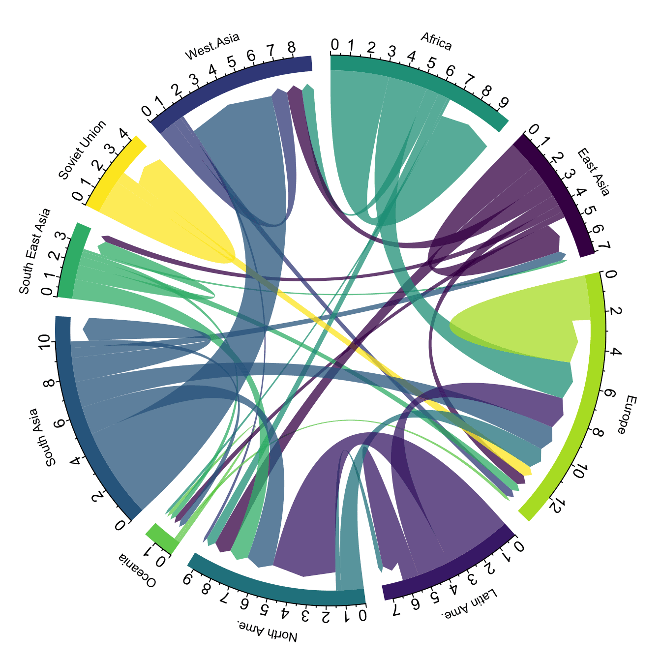
Note: this plot is made using the circlize library, and very strongly inspired from the Migest package from Gui J. Abel. Read more about this story here.
Source: www.data-to-viz.com
For more information on systems engineering related conferences and meetings, please go to our website.
The featured event for this edition is:
39th International Conference on Conceptual Modeling
November 3-6, 2020, Vienna, Austria (Hosted Virtually)
The world is being reconstructed through software and data. Conceptual models seem mandatory to cope with this gigantic transformation that is unprecedented in the history of humankind. Not only do they build a solid foundation for designing software systems, they also foster the empowerment of users and help us to develop images of possible future worlds. However, recent developments in AI challenge this pivotal role of conceptual models. Some AI proponents go so far as to predict the end of conceptual modeling, for an ostensibly convincing reason: machine learning will enable automated software construction, both faster and at much lower costs. These contradictory assessments make it especially exciting to reflect upon the foundations of conceptual modeling and the limitations of inductive approaches to software creation.
The ER conference has been the leading conference on conceptual modeling for many years. In continuation of this tradition, ER 2020 is dedicated to providing a forum for discussing the present and future role of conceptual modeling with regard to enabling and managing change.
13.1 Update to the PPI Map
PPI adds another 5 locations to its training and personnel map: Darmstadt, Hawaii, Santiago, La Serena and Portland, MN. Join PPI in the crusade to make a world a better place through systems engineering.
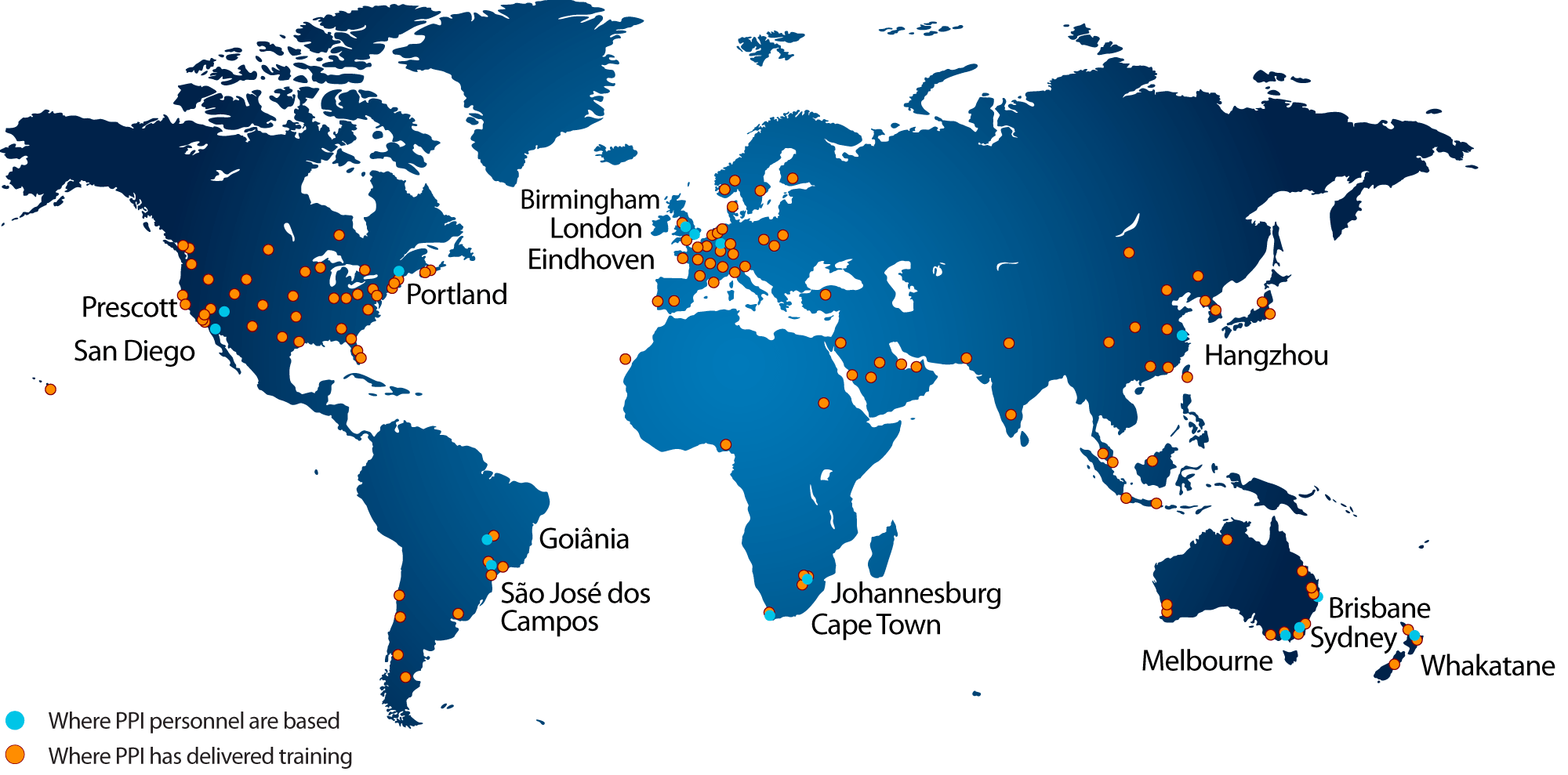
13.2 CTI Successfully Conducts First Ever INCOSE SEP Exam Prep Workshop in India
Over 12-16 October 2020, CTI Managing Director René King facilitated CTI’s first ISEP Workshop to Indian delegates. The workshop, just like CTI’s standard ISEP courses, was dedicated to accelerating the journey to SEP certification for all who participated, via an immersive journey through the INCOSE Systems Engineering Handbook V4. The workshop was hosted from 6pm to 9.30pm Indian Standard Time, from Monday to Friday and was a truncated version of CTI’s standard ISEP course which takes place over four full working days. The Asia-Oceania region boasts about 10% of the total number of SEPs worldwide.
As of October 2020, there are 3731 SEPs in the world, according to INCOSE. CTI is proud to have played a role in the journey of many of those SEPs, and hopes to see that number grow substantially over the coming years, for the betterment of systems engineering practice and engineering at large.
To register for an upcoming course, visit the INCOSE SEP Exam Prep Schedule.
For a full public PPI Live-Online™ training course schedule, please visit https://www.ppi-int.com/ppi-live-online/
For a full public PPI training course schedule, please visit https://www.ppi-int.com/course-schedule/
To enquire about corporate training delivered worldwide, please visit ppi-int.com/corporate-training/
For a full public CTI Live-Online™ INCOSE SEP Exam Preparation course schedule, please visit https://certificationtraining-int.com/incose-sep-exam-prep-course/
To enquire about CTI Live-Online™ INCOSE SEP Exam Preparation Training for your organization, please visit https://certificationtraining-int.com/on-site-training/
15. Upcoming PPI Participation in Professional Conferences
PPI will be participating physically in the following upcoming events. We support the events that we are sponsoring, and look forward to meeting old friends and making new friends at the events at which we will be exhibiting.
The INCOSE International Workshop 2021
Date: 29 – 31 January, 2021
Location: Virtual Event
The INCOSE International Conference 2021
Date: 16 – 22 July, 2021
Location: Honolulu, USA
Kind regards from the PPI SyEN team:
Robert Halligan, Editor-in-Chief, email: rhalligan@ppi-int.com
Ralph Young, Editor, email: ryoung@ppi-int.com
René King, Managing Editor, email: rking@ppi-int.com
Project Performance International
2 Parkgate Drive, Ringwood, Vic 3134 Australia
Tel: +61 3 9876 7345
Tel Brasil: +55 12 9 9780 3490
Tel UK: +44 20 3608 6754
Tel USA: +1 888 772 5174
Tel China: +86 188 5117 2867
Web: www.ppi-int.com
Email: contact@ppi-int.com
Copyright 2012-2020 Project Performance (Australia) Pty Ltd, trading as
Project Performance International
Tell us what you think of PPI SyEN. Email us at syen@ppi-int.info.
- Burns, L.: “Complex systems characteristics in the context of Systems Engineering,” Paper presented to NASA Systems Engineering Research Consortium, The University of Alabama in Huntsville, Huntsville, AL, February 2016. ↑