IN THIS EDITION
1. Quotations to Open On
2. Feature Articles
2.1 A Requirement Evaluation Metric for Microsatellite Missions by Marcelo Essado
2.2 Requirements for the Business Aircraft of the Future by Ronaldo Gutierrez
3. Additional Articles
3.1 Reuse in Requirement Management for Rail Projects by Aurangzeb Awal
3.2 INCOSE Americas Sector Activities by Tony Williams
4. Systems Engineering News
4.1 Johns Hopkins Whiting School of Engineering’s Mapping Tool Tracks Coronavirus Outbreak in Real Time
4.2 The Coronavirus: What You Can Do to Help in Simple Terms
4.3 Message from INCOSE President Regarding COVID-19
4.4 IEEE Adopts New Diversity Statement
4.5 Mapping Potholes by Phone
4.6 Using Panarchy to Change a Complex System
4.7 MITRE (USA) Unveils Laboratory Focused on Autonomous Technology
4.8 How Can We Combat Climate Change?
4.9 Order of the Engineer Celebrates 50th Anniversary
4.10 Standards Development: ISO24641 Methods and Tools for Model-Based Systems
5. Featured Organizations
5.1 MITRE
5.2 American Society of Agricultural and Biological Engineers
5.3 Caspian Engineers Society
6. News on Software Tools Supporting Systems Engineering
6.1 The REUSE Company Maps out INCOSE 2019 Rules with SE Suites Metrics
6.2 New Web Interface for Requirements Management ALM Solution
6.3 Leverage Standardized Encryption and Licensing for Modelica Libraries
7. Systems Engineering Publications
7.1 Diversity in Systems Engineering INSIGHT Available
7.2 Illuminating the world – the Choice of the Era to Rise above the Atmosphere
7.3 An Elegant Puzzle: Systems of Engineering Management
7.4 Personal Information Security & Systems Architecture: Techniques for Personally Identifiable Information Management in a Business
7.5 Visual Models for Software Requirements – Developer Best Practices
7.6 Software Requirements – Developer Best Practices (3rd Ed)
7.7 DevOps: A Software Architect’s Perspective
8. Education and Academia
8.1 CIMdata and SMS ThinkTank Announce New Systems Modeling & Simulation Certificate Program
8.2 The Roux Institute of Northeastern University
9. Some Systems Engineering-Relevant Websites
10. Standards and Guides
10.1 ISO/IEC/IEEE 29148:2018 Systems and software engineering — Life cycle processes — Requirements engineering
10.2 The New International System of Units (SI): Quantum Metrology and Quantum Standards
10.3 The IEEE Software & Systems Engineering Standards Committee (S2ESC)
11. Some Definitions to Close On
11.1 DevOps
11.2 Stakeholder
11.3 Multi-Factor Authentication (MFA)
12. Conferences and Meetings
12.1 27th International Conference on Systems Engineering [25 – 27 August, 2020 – Las Vegas, NV (USA)]
13. PPI and CTI News
14. PPI and CTI Events
15. Upcoming PPI Participation in Professional Conferences
1. Quotations to Open On
“Of course, we want to be agile. That doesn’t mean proceeding in ignorance of what is already known!”
Robert John Halligan
“I have no special talents. I am only passionately curious.”
Albert Einstein
“With the right mindset, what is each of us capable of?”
Wim Hof
2. Feature Articles
2.1 A Requirement Evaluation Metric for Microsatellite Missions
by
Marcelo Essado
EMSISTI Space Systems & Technology
Email: marcelo.essado@emsisti.com.br
Abstract
Available data demonstrates that defective requirements are a dominant cause of cost and schedule problems on space programs. This article presents results obtained from the study of a Requirement Evaluation Metric applied on a small technological microsatellite. The requirement evaluation metric is a structured methodology for measuring the quality of requirements, individually and collectively, by means of ten individual quality metrics. The paper describes the satellite mission, the Requirement Evaluation Metric used, and how it was applied. In addition, the requirements engineering process is shown in terms of the problem statement. The main contribution of this study is the establishment of a Requirement Evaluation Metric on a systematic approach to refine a critical satellite requirements operation for space applications, called Conformance and Fault Injection for Requirement Refinement (COFI-ref).
Copyright © 2020 by Marcelo Essado. All rights reserved.
- Introduction
It is known that the software development process is conceptually an abstract form of model transformation. It starts from a stakeholder model requirements analysis and continues through the system design model11, 12. The success or failure of such transformation depends mainly on the initial model that captures the user needs. The same process occurs to acquire the user concerns for a space mission operation. Advanced satellite systems require new approaches not only in the area of the satellite itself but also in the field of operations2, 3, 4. This paper presents a Requirement Evaluation Metric applied in the early phases of a technological microsatellite requirements as part of the Verification and Validation (V&V) plan. The evaluation metric used, called Requirements Structural Model, was presented for the first time by Robert J. Halligan10. The goals of the Program are: (a) generation of technological innovations for the aerospace sector; (b) strengthening of national industry; (c) dissemination of knowledge; and (d) training of human resources. This task is performed through conceptualization, design, and development of small satellites and applied research related to the national interests. The COFI-ref (Conformance and Fault Injection for Requirement Refinement) approach is based on a testing methodology called COFI (Conformance and Fault Injection). As part of the ISVV (Independent Software Verification and Validation) process, the results with the application of the COFI methodology have surprised the mission management, because many errors were found1, 2. However, the errors were found only in the latter phases. Thus, a variation of COFI, the COFI-ref was co-developed by the author, to be applied in early phases of a technological microsatellite as part of the mission requirements refinement. With this opportunity, it was possible to demonstrate the effectiveness of the designer’s attention to incomplete, ambiguous, and incorrect requirements that occur during the software development process, and to operations definitions. Finally, the Requirement Evaluation Metric was applied during the COFI-ref in order to measure the requirement refinement provided by this approach.
- Microsatellite Mission Concept
The System Engineering Team is responsible to produce the needed documents at the system-level, and through a formal review delivery, the respective documents to the V&V Team, as the starting point of the refinement process, part of the COFI-ref approach depicted later. The Document Requirements Definition (DRD) is the input for the refinement process.
The microsatellite mission is related to an environmental data collection system, and it can be applied to agriculture and animal creation control and monitoring. Figure 1 shows the concept of the space and ground segments.
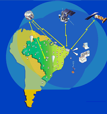
Figure 1: Small Satellites for Environmental Data Collection, Agriculture, and Animal Creation Control and Monitoring (Source: http://sinda.crn.inpe.br/PCD/SITE/novo/site/index.php)
This section describes the part of the DRD that contextualizes the problem domain. The mission cycle comprehends the following phases:
- Assembly, Integration, and Test Phase (AITP);
- Launch Readiness Phase (LRP);
- Pre-launch Phase (PLP);
- Launch and Early Orbit Phase (LEOP);
- Commissioning Phase (CP);
- Operational Phase (OP); and
- Decommissioning Phase.
As part of the Mission Description Document the Microsatellite has 8 operational modes:
- Launch Mode;
- Survival Mode;
- Testing Mode;
- Alignment Mode;
- Payload Mode;
- Experimental Mode;
- Operational Mode; and
- Propulsion Mode.
Figure 2 shows the operational modes and the relationship with Mission Phases. For example, the Launch and Survival Modes is activated in Launch and Early Orbit Phase as well Testing Mode will be activated in the Commissioning Phase, and so on.
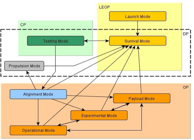
Figure 2: Operation Modes and Mission Phases activation
The Operation Modes are described below in order to better understand the requirement evaluation approach.
- Launch Mode – During the launch, the s/c (spacecraft) stays in launch mode. It fulfills the launch provider requirements: there is no electric power supply for all subsystems and all mechanisms are securely locked.
- Survival mode – After ejection, the s/c changes into the survival mode. In this mode, the attitude of the s/c and its spin rate is undefined. In this mode all payloads (operational and experimental) are turned off. In this mode the task of the s/c is to keep a positive energy budget over one orbit and to ensure its ability to communicate well. In the case of failure or malfunction that affects the whole s/c, it switches into the survival mode automatically, independent of the current mode.
- Testing mode – From the survival mode, the s/c switches into the testing mode. This mode tests all the subsystems and payloads before passing the s/c to the customer. The testing mode provides all the functions of the survival mode, and in this mode the first telecom and data will be received. After this mode, the s/c can change to the alignment mode or the payload mode. Starting from this mode, it also can be decommissioned.
- Alignment mode – The alignment mode is for de-tumbling the s/c and aligning it to specified orientations in the flight coordinate system. It is an intermediate mode from the Testing mode to the Payload mode, the Experimental mode, the Operational mode, or the Propulsion mode.
- Operational mode – In this mode, the experimental payload is turned off and just the operational payload is working, in addition to the subsystems.
- Propulsion mode – The Propulsion Subsystem is used for de-orbiting and therefore belongs to the Disposal Phase.
- Payload mode – In this mode, achieved from Alignment mode by ground command, all satellite subsystems including the payload, but excluding the possible propulsion system, are in their final operating configuration. The mission technological data is being collected and transmitted to Earth during visible passes.
- Experimental mode – In this mode, besides the subsystems, just the experimental payloads are working. This mode provides time to do experiments and to test, for example, the new onboard computer.
- COFI-ref Approach
The COFI testing methodology1, 2, 14 consists of a systematic way to create test cases for reactive systems. The system to be tested is modeled in Mealy machines. In COFI the system behavior is partially represented in state models where transitions represent inputs and outputs of the interfaces. The main steps of the COFI-ref approach are:
- DRD Acquisition,
- Identification,
- State-Based Modeling, and
- Requirement Refinement.
For COFI Methodology the steps are Identification, State-Based Modeling, and Automatic Test Case Generation where steps 2 and 3 were reused on COFI-ref.
The DRD (Document Requirements Definition) is the input of the COFI-ref. In the first step, the team in charge of the system specification, prior to a project review, provides the DRD for the COFI-ref team. This is what we call “DRD Acquisition”. The second and third steps were extracted from the standard COFI methodology. The tasks involved in the second step, Identification, are:
- Identify the services that a user recognizes;
- Identify hardware faults that can occur (and that system shall resist);
- Identify the events (inputs) and reactions (outputs) of the system.
For step 3, we have to create partial models based on Finite State Machines. The tasks involved are to define, for each Service previously created:
- Normal Operation Mode;
- Specified Exception;
- Sneak Paths; and
- Fault Tolerant.
For the last step, the Requirement Refinement represents the refinement itself requiring the execution tasks:
- State Models analysis, based on its transitions;
- Question elaboration; and
- Requirements modification.
For details of the COFI-ref approach and results, see previous works13, 14.
- Requirement Evaluation Metric
Requirements quality, in order to satisfy the user needs and system performance, should follow the same criteria no matter the area or description being written about. That is, the requirements must, in their expression, exhibit certain attributes as quality factors10, 13. Those quality factors can be classified and are defined as follows:
- Correctness: refers to an absence of errors in the statement of the requirement;
- Completeness: refers to the quality that the requirement contains all of the information that satisfies constraints and conditions to enable its implementation and verifying process;
- Consistency: requires that the requirement not be in conflict with any other, nor an element of its own structure;
- Clarity: requires that the requirement be readily available and understandable without semantic analysis;
- Non-ambiguity: requires that there is only one semantic interpretation of the requirement;
- Connectivity: refers to the property whereby all of the terms within other requirements are adequately linked in terms of words and definitions;
- Singularity: refers to the property that the requirement cannot sensibly be expressed as two or more requirements having different meanings, like verbs or objects;
- Testability: refers to the existence of a finite and objective process with which to verify that the requirement has been satisfied;
- Modifiability: requires that any change in the requirement can be made completely and consistently in order to obey the previous criteria; and
- Feasibility: requires that a requirement be able to be satisfied within natural physical phenomena and that it applies to the project.
The Requirement Evaluation Metric is based on those criteria, once it is possible to establish a measurement to characterize the quality and quantify the requirements. The metric is called Requirement Structural Model and it was developed by Robert J. Halligan10. Requirements are most commonly expressed as natural language statements, although graphical and formal mathematical requirements languages are widely used in many types of system modeling. The author indicates that for natural language types of expression, requirements quality metrics may be developed through the parsing of each requirement statement into the elements of a structural model of a template. Table 1 shows one example of our technological microsatellite mission system requirement parsed into the template. This procedure was used in all system requirements evaluated by the COFI-ref approach13.
Original Requirement:
Alignment mode – The alignment mode is for de-tumbling the spacecraft and aligning it to specified orientations in the flight coordinate system. It is an intermediate mode from the Testing mode to the Payload mode, the Experimental mode, the Operational mode, or the Propulsion mode.
Table 1 (A): Requirement Structural Template
|
Element |
Text |
|
Actor |
The alignment mode |
|
Conditions for Action |
|
|
Action |
Is for detumbling |
|
Constraints of Action |
|
|
Object of Action |
the spacecraft |
|
Refinement/Source of Object |
|
|
Refinement/Destination of Action |
to specified attitude in the flight coordinate system. |
|
Other |
It is an intermediate mode from the Testing mode to the Payload mode, the Experimental mode, the Operational mode, or the Propulsion mode. |
Table 1 (B): Requirement Structural Template
|
Element |
Text |
|
Actor |
The alignment mode |
|
Conditions for Action |
|
|
Action |
Is for aligning |
|
Constraints of Action |
|
|
Object of Action |
it (the spacecraft) |
|
Refinement/Source of Object |
|
|
Refinement/Destination of Action |
to specified orientations in the flight coordinate system. |
|
Other |
It is an intermediate mode from the Testing mode to the Payload mode, the Experimental mode, the Operational mode, or the Propulsion mode. |
The author says that a strong requirement shall have each applicable element of the requirement (presented in Table 1), and the requirement overall, satisfying each of the quality factors described earlier. This ideal provides a basis of the development of requirements quality metrics. The basis for the development of requirement quality metrics is defined below:
IRQ – Individual Requirement Quality
This metric is applicable for a single requirement and has to be numbered between 0 and 1, where 1 represents a ‘perfect’ requirement and 0 (zero) a totally defective one. The metric is developed through a classification and the parsed version of the requirement, following the following steps:
- To determine which of the possible seven elements of the structure are applicable and assigning value of 1 to each applicable element;
- To assess each element of the parsed requirement against the quality factor criteria, and scoring each applicable element as 1 (satisfactory) or 0 (unsatisfactory). An element may be unsatisfactory because it is missing, or because it is defective in some other way;
- To calculate the metric by dividing the sum of the applicable element values into the sum of the element scores.
IQF1 – IQF10 – Individual Quality Metrics
Ten individual quality factors correspond to the ten requirement quality factors as follows:
IQF1 – Correctness;
IQF2 – Completeness;
IQF3 – Consistency;
IQF4 – Clarity;
IQF5 – Non-Ambiguity;
IQF6 – Connectivity;
IQF7 – Singularity;
IQF8 – Testability;
IQF9 – Modifiability;
IQF10 – Feasibility.
These metrics assume, for an individual requirement a value on the unit interval [0,1] depending on whether the requirement overall has a defect of type 0 (zero) or not (1). The application of this metric follows the following steps:
- To classify the requirement statement according the eight elements presented in Table 1 earlier;
- To assign, for each of the elements identified on the previous step, 1 if the statement presents the element or 0 (zero) if not;
- To analyze each of elements identified against the ten quality factors and score the requirement to 1 if its correct and 0 (zero) if not;
- To evaluate each element identified on step (a) against the ten quality factors and score to 1 if it is satisfactory or 0 (zero) if not;
- To calculate the Individual Requirement Quality for each requirement dividing the sum of the elements with the sum of the score.
Requirements which have been omitted may be accounted for by estimating an omission ratio for each requirement that is present. The omission ratio is the number of new requirements that would be created if all possible areas of omission suggested by the requirement that is present were pursued to resolution. The omission ratio must be constructed such as to support aggregation of requirements having different omission ratios.
The quality metrics for a set of requirements correspond to, and are produced from, the individual metrics, as follows (for n requirements):
RQ – Requirements Quality
Equation (1)
QF1 – Correctness
Equation (2)
QF2 – Completeness
Equation (3)
Where:
- n is the total of requirements evaluated;
- QF2 can be negative, once take into account the omission ratio;
- QF3 to QF10 are derived as for QF1.
Table 2 illustrates the construction of the Requirement Structural Model based on parsing of the original requirement statement presented earlier.
Table 2 (A): Construction of Requirement Quality Metrics.
|
Element |
Text |
Applicability |
Score |
Metric Name |
Metric Value |
|
Actor |
The alignment mode |
1 |
1 |
IQF1 |
0 |
|
Conditions for Action |
0 |
0 |
IQF2 |
1 |
|
|
Action |
is for de-tumbling |
1 |
1 |
IQF3 |
0 |
|
Constraints of Action |
0 |
IQF4 |
0 |
||
|
Object of Action |
the spacecraft |
1 |
0 |
IQF5 |
1 |
|
Refinement/Source of Object |
0 |
1 |
IQF6 |
1 |
|
|
Refinement/Destination of Action |
to specified attitude in the flight coordinate system. |
0 |
0 |
IQF7 |
0 |
|
Other |
from the Testing mode to the Payload mode, Experimental mode, the Operational mode or the Propulsion mode. |
– |
– |
IQF8 |
1 |
|
SUM |
3 |
3 |
IQF9 |
0 |
|
|
Metric IRQ |
1,00 |
IQF10 |
1 |
||
|
Omission Ratio |
1 |
SUM |
5 |
||
Table 2 (B): Construction of Requirement Quality Metrics.
|
Element |
Text |
Applicability |
Score |
Metric Name |
Metric Value |
|
Actor |
The alignment mode |
1 |
1 |
IQF1 |
0 |
|
Conditions for Action |
1 |
0 |
IQF2 |
1 |
|
|
Action |
is for aligning. |
1 |
1 |
IQF3 |
0 |
|
Constraints of Action |
1 |
IQF4 |
0 |
||
|
Object of Action |
spacecraft |
0 |
0 |
IQF5 |
1 |
|
Refinement/Source of Object |
1 |
1 |
IQF6 |
1 |
|
|
Refinement/Destination of Action |
to specified orientations in the flight coordinate system. |
0 |
0 |
IQF7 |
0 |
|
Other |
from the Testing mode to the Payload mode, Experimental mode, the Operational mode or the Propulsion mode. |
– |
– |
IQF8 |
1 |
|
SUM |
5 |
3 |
IQF9 |
0 |
|
|
Metric IRQ |
0,60 |
IQF10 |
1 |
||
|
Omission Ratio |
1 |
SUM |
5 |
||
The following section presents the results obtained applying the Requirement Structural Model to the technological Microsatellite system requirements.
- Application of Requirement Quality Metrics
The Requirement Structural Model was applied to system requirements during the earlier phases of the Mission Requirements Definition. This procedure was used in a way to measure the quality of the COFI-ref refinement approach.
This section shows the results that were achieved applying the Requirement Structural Model to the Document Requirement Definition (DRD) version 1.0, and then to version 1.1, right after the COFI-ref approach.
Table 3 presents the results obtained by applying the Requirement Structural Model to each version of the DRD. The first and second columns are the quality factors acronym and its name. The third and fourth columns are the mean obtained for each version of the DRD calculated using Equation (1), derived above.
Table 3: Requirement Structural Model results
|
Acronym |
QFs |
Mean (RQ) |
|
|
DRD 1.0 |
DRD 1.1 |
||
|
QF1 |
Correctness |
0 |
0,58 |
|
QF2 |
Completeness |
-1,27 |
0,32 |
|
QF3 |
Consistency |
0,27 |
0,77 |
|
QF4 |
Clarity |
0,33 |
0,81 |
|
QF5 |
Non-Ambiguity |
0,67 |
0,97 |
|
QF6 |
Connectivity |
0,73 |
0,9 |
|
QF7 |
Singularity |
0,27 |
0,58 |
|
QF8 |
Testability |
0,87 |
0,77 |
|
QF9 |
Modifiability |
0,4 |
0,55 |
|
QF10 |
Feasibility |
0,53 |
0,9 |
With these results we can deduce:
- That there is a considerable increase in the quality factors value between the DRD versions;
- The success of applying the Requirement Quality Metrics.
To better understand the results, a discussion of each quality factor is needed as follows:
QF1 – Correctness
This attribute evaluates the absence of errors in the statement of requirement, in terms of all quality factors and/or grammatical ones: that is, the DRD 1.0 shows that the set of requirements was incorrect while the new version, DRD 1.1, have a considerable improvement.
QF2 – Completeness
This attribute evaluates if the requirement satisfies all of the information to enable the condition of its implementation and verifying process. For DRD version 1.0, the negative value obtained has its origin in omission ratio. In other words, in this version of DRD there were some requirements that are not complete, generating a high score of omission ratio, which did not happen on DRD version 1.1.
QF3 – Consistency
This attribute evaluates if the requirement is not in conflict with any other, nor an element of its own structure. The result shows that COFI-ref approach was able to identify precisely the elements in the requirement statement.
QF4 – Clarity
This attribute evaluates if the requirement is understandable in terms of semantic analysis. The result shows that COF-ref approach could improve the requirement statement. This was possible once some of the DRD 1.0 requirements have been divided into smaller ones.
QF5 – Non-Ambiguity
This attribute evaluates if the requirement is only one semantic interpretation. The result shows that the increment of 0.3 was possible because of QF4, once one requirement statement on DRD 1.0 generates two or more requirements.
QF6 – Connectivity
This attribute evaluates if all terms within other requirements are adequately linked. The increased value of the result was possible because after COFI-ref approach, the requirements were better classified into the eight elements, as shown is Table 1.
QF7 – Singularity
This attribute evaluates the property of the requirement to be expressed in two or more requirements with different meanings. The increase in its value shows that the requirement statement can be more accurately classified into the eight elements, as shown is Table 1.
QF8 – Testability
This attribute evaluates if the requirement can be properly verified. This is a significant result, once the COFI-ref approach is part of a Verification & Validation technique. The value obtained on DRD 1.0 is higher than DRD 1.1 because of two factors: (a) new requirements were created in this last version, and (b) some expression like “to be defined” was elaborated.
QF9 – Modifiability
This attribute evaluates that requirement can be made completely and consistently, in accordance with the previous quality factor. The increase in value of DRD 1.1 was not higher because of the same factors presented on QF8.
QF10 – Feasibility
This attribute evaluates if the requirement is able to be satisfied within physical phenomena and applies to the project. The improvement on DRD 1.1 shows that this attribute is directly proportional to the understanding of the requirement in terms of all quality factors.
Figure 3 presents the evolution of system requirements between DRD versions. The negative value on DRD 1.0 was calculated using Equation (3), which considers the sum of omission ratio. Through this point of view, we can clearly conclude that DRD 1.1 remained in the unitary interval [0,1], showing that COFI-ref approach improves the quality of system requirements, according to the Requirement Structural Mode.
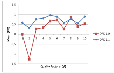
Figure 3: System Requirements evolution through Requirement Quality Metric used.
- Conclusions
This article has provided the results obtained by applying a Requirement Evaluation Model to system requirements of a technological microsatellite.
It was shown that the Requirement Structural Model can be easily applied to evaluate requirements qualities; also, it can be extended to all phases of a system life-cycle. In addition, the COFI-ref approach has been successfully applied to refine requirements using formal language13. The refinement is based on the grammar of the language that it is applied. Many authors describe the refinement through some mathematical formalism. However, one of the COFI-ref approach concerns is hidden in the mathematical formalism and guarantees that these properties still be followed by the use of Finite State Machines.
The cost of implementing these metrics is suitable – according to Halligan10 a reasonable cost for implementing metrics is approximately two percent of the cost of the total requirements engineering effort.
The lessons learned indicate that the more the system analyst is trained to achieve additional effectiveness, the better the results obtained by COFI-ref. In other words, the analyst must have at least an intermediate knowledge concerning the approach and techniques such as formal methods, automata theory, analysis, and system development. Requirements management benefits substantially from the use of computer-based tools which facilitate, in particular, efficient text handling, rigorous requirements allocation, and the creation and maintenance of peer and parent-child relationships for requirements traceability purposes. Halligan10 has shown that metrics prove to be most easily calculated when a CASE environment is used for those other aspects of requirements management.
Acknowledgements
The author is grateful to the Brazilian Space Agency (AEB), Brazilian National Institute for Space Research (INPE), Dr. Ana Maria Ambrosio from INPE and EMSISTI Space Systems & Technology for their support.
References
1 Ambrosio, A. M.; Martins, E.; Vijaykumar, N.L.; de Carvalho, S.V. “A Conformance Testing Process for Space Applications Software Services.” JACIC – Aerospace Computing, Information, and Communication, Vol.3, N.4, pp.146-158. USA: American Institute of Aeronautics and Astronautics (AIAA), April 2006.
2 Ambrosio, A. M.; Mattiello-Francisco, M. F.; Martins E. “An Independent Software Verification and Validation Process for Space Applications.” In: CONFERENCE ON SPACE OPERATIONS 9. (SPACEOPS 2008), 2008, Hidelberg. Proceedings… 2008. p. 9. CD-ROM. (INPE-15303-PRE/10112).
3 Best Practices Working Group of the Space Operations and Support Technical Committee (SOSTC) of the American Institute of Aeronautics and Astronautics. “Satellite Mission Operations Best Practices.” AIAA Space Operations and Support Technical Committee (SOSTC). April, 2003
4 ECSS-E-10 Part 1B, Space Engineering – System Engineering – Part 1: Requirements and Process. 18 November 2004.
5 ECSS-E-40 Part 2B, Space Engineering – Software – Part 2: Document requirements definitions (DRDs). 31 March 2005.
6 ECSS-E-70 Part2A, Space Engineering – Ground systems and operations – Part 2: Document Requirements Definitions (DRDs), 2 April 2001.
7 ECSS-E-ST-70-11C, Space Engineering – Space segment operability. 31 July 2008.
8 ECSS-M-ST-10C, Space Project Management – Project Planning and implementation. Revision 1, 6 March 2009.
9 Essado, M, et. al. Montagem, Integração e Teste das Interfaces Eletrônicas de Controle e Comunicação de Dados de um Microssatélite Nacional. ISBN: SIGE (Simpósio de Aplicações Operacionais em Áreas de Defesa), 24 a 26 SET de 2019.
10 Halligan, R. “Requirements Metrics: The Basis of Informed Requirements Engineering Management.” In: COMPLEX SYSTEMS ENGINEERING AND ASSESSMENT TECHNOLOGY WORKSHOP, Proceedings of the Naval Surface Warfare Center, Dahlgren, Virginia, 1993.
11 IBM Corporation. “Get It Right the First Time: Writing Better Requirements.” 2008.
12 IEEE Std. 830-1998. “IEEE Recommended Practice for Software Requirements Specifications.” IEEE Computer Society, 1990.
13 Morais, M. H. E. Sistemas Espaciais: Refinamento de Requisitos em Missões de Satélites. Novas Edições Acadêmicas, 123 páginas, ISBN-10: 978-3639837841, Julho de 2015.
14 Morais, M. H. E, Ambrosio, A. M., “A new model-based approach for analysis and refinement of requirement specification to space operations”. SpaceOps 2010 Conference, 2010, Huntsville. SpaceOps 2010 Conference, 2010.
15 Pontes, R. P.; Morais, M. H. E.; Veras, P. C.; Ambrosio, A. M.; Villani E. “Model-based Refinement of Requirement Specification: A Comparison of two V&V Approaches.” COBEM, International Congress of Mechanical Engineering, November 15-20, 2009, Gramado, RS, Brazil.
About the Author
 Marcelo Essado has been working with space systems more than 15 years. He is author of the book “Sistemas Espaciais: Refinamento de Requisitos em Missões de Satélites” ed. NEA, 132 pages, ISBN-13: 978-3639837841 (Space Systems: Requirement Refinement in Satellite Missions) and several technical and scientific papers. He has founded two startups, is director of EMSISTI Space Systems & Technology, and a member of the directory board of the Brazilian Civil Aerospace Association. He has served as a reviewer for the Brazilian Rocket and Satellite Universities Competition. Marcelo is a speaker, advisor, and educator with experience concerning space system engineering, artificial intelligence applied for decision driven, digital image processing and control, and business development. He also has been involved in developing social and educational projects.
2.2 Requirements for the Business Aircraft of the Future
by
Independent Researcher
Email: ronaldo.gutierrez@mail.concordia.com
The purpose of the article is to elicit a complete set of requirements for the business aircraft of the future. The complete set of requirements is vast, covering several aspects of the aircraft and its context. The article employs guidance from the international standard ISO/IEC/IEEE 29148:2018 to elicit the complete set of requirements. The complete set of requirements includes 57 stakeholder requirements and 101 system requirements. The complete set of requirements provides the foundation to: 1) facilitate the conversation in the systems engineering community concerning eliciting complete sets of requirements in the aerospace sector using traditional text-based requirements; 2) utilize the set of requirements to practice the attributes and characteristics of well-formed sets of requirements specified in the standard; and 3) use the set of requirements as a baseline to understand the scope of Model Based Systems Engineering (MBSE) in the elicitation of a complete set of requirements in the aerospace sector.
Editor’s Note: The standard referenced in this article is featured in the Standards section of this issue of PPI SyEN.
Copyright © 2020 by Ronaldo Gutierrez. All rights reserved.
Introduction
People have mobilized around the world since ancient civilizations. The United Nations Department of Economic and Social Affairs (2018) states that 55% of the world’s population lives in urban areas today, and the organization expects the proportion to increase to 68% by 2050. This trend has increased emissions, noise, and congestion in urban areas; thereby, reducing the quality of life or well-being of cities’ inhabitants. Sustainable mobility is a solution to alleviate the challenge of congestion, emissions, and noise in day-to-day transportation of people in the smart cities of the near future.
People have used land, air, and water means to move effectively and efficiently in and between cities. Thus, land, air, and water composed the whole mobility system. As the capacity of land and water transportation has become saturated, innovations in air mobility can decrease the stress of emissions, noise, and congestion. Studies in air mobility solutions suggest that a niche market of people (e.g., top management, other managers, and technical/sales/service staff) in each city is willing to travel quickly, safely, securely, sustainably, comfortably, and connectedly in their day-to-day journeys (National Business Aviation Association, 2014); so, they need a new kind of business aircraft. This business aircraft must fly safely, securely, and sustainably within smart cities and near airports in order to provide all the possible trips that the niche market needs to perform without interrupting its daily work and productivity.
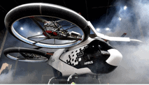
The lack of runways inside cities leads to the adoption of vertical take-off and landing (VTOL) aircrafts using heliports or other landing pads (e.g., vertiports) as the preferred alternative to travel compared to traditional aircraft (Nichols & Dyment, 2019). In addition, an increased demand of flight for the next 10-20 years is forecast (Meredith, 2019). This demand puts at risk the ability to recruit pilots; thus, an autonomous unmanned aircraft is a feasible solution to enable air trips in cities. Connection with the environment improves the aircraft automation capability in order to assure the safe and pleasant trips of people. An electric power system reduces emission and noise in cities during the trips. Therefore, the business aircraft of the future is an e-VTOL vehicle that must fly safely, securely, and sustainably, within cities and near airports. For example, we can imagine the aircraft flying in the context of operation in Figure 1.
Wrong requirements lead to significant delays and cost overruns in megaprojects (Flyvbjerg, 2014), for example, imagine the development of the clean sheet design for the e-VTOL business aircraft of the future. Requirements engineering as a research area and a significant practice competency in systems engineering is maturing, but it is not easily accessible to entrants to the profession (Wheatcraft, 2019). To enable the participation of entrants and perhaps to foster their collaboration with matured systems engineers, this article elicits a complete set of requirements for the aircraft of the future; such a meaningful megaproject for 2020 and beyond that has called the attention of the International Civil Aviation Organization (ICAO) (2019a) and the National Research Council Canada (2019).
The article is organized as follows:
- Section 2 defines the scope of the context of operation to elicit a complete set of requirements for the aircraft of the future.
- Section 3 defines the meaning and context of the complete set of requirements.
- Section 4 overviews the methodology to elicit set of complete requirements.
- Section 5 employs the methodology to state the elicited complete set of requirements.
- Section 6 briefly compares the employed methodology against others.
- Section 7 summarizes and concludes the article.
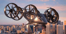
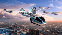
Figure 1: Context of operation: smart city (ciena, 2019), airport (Joint Planning and Development Office, 2007), smart city near airport (Joint Planning and Development Office, 2010), and e-VTOL Nexus (Bell flight, 2019a).
Context of Operation
Figure 1 describes the context of operation for the aircraft. The major elements in the context of operation are the smart city, the smart airport, the path from the city to the airport or vice-versa, and the aircraft. The remainder of this section describes each element with the purpose of creating a background to understand the requirements. The context of operation is the source to elicit the complete set of requirements.
Smart Airports
The aircraft shall transport passengers and cargo from/to airports. Systems engineers need to understand the role and evolution of airports to define safety, security, and sustainability (S3). Airports are the nexus at which passengers transfer between air and surface modes of travel. As a system, an airport comprises the 3 sub-systems in Figure 2: urban access/egress, landside, and airside. Urban access/egress moves passengers and cargo to and from airports (bottom of Figure 2). Landside prepares passengers and cargo for air transportation (middle of Figure 2). Airside oversees the physical movement of aircraft at airports (top of Figure 2).
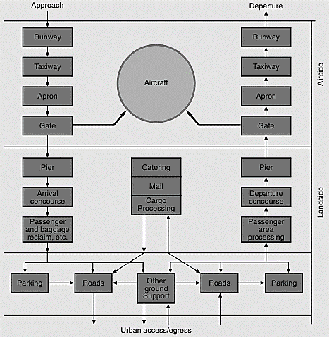
Figure 2: The airport system (MacKinnon, Sowden, Russell, and Stewart, 2004, p. 100)
The International Air Transport Association (IATA, 2015) has envisioned the airport of the future. The airport of the future brings together and coordinates in the airport space 10 areas: 1) airport infrastructure design, 2) security, 3) passenger, 4) cargo, 5) ground operations, 6) baggage, 7) financial systems, 8) information and technology, 9) safety and flight operations, and 10) environment.
A smart airport facilitates making a reality the airport of the future. As a result, a smart airport enables the 10 areas in the airport of the future. The smart airport intends to cover the entire airport space to provide a seamless end-to-end journey for passengers, baggage, cargo, and aircrafts (IATA, 2019). To achieve this goal, the initiative for a smart airport must work together with the principal organizations in Figure 3.
This article does not investigate any existing regulation concerning flying near an airport or a smart airport, but it does try to highlight the importance of such regulations. The article expresses the notion that the management of safety comes from the definition of risk areas. For example, bird strike accidents in the past have led regulators to define hazardous areas near airports in order to avoid the reoccurrence of the incidents. Lessons learned from this example can be extrapolated for safety relative to the context of new aircraft flying near smart airports. Flying near smart airports shall respect and interoperate with the initiatives in the 10 areas, while also ensuring safety in the air transportation system. Flying near smart airport is a necessary capability for the business aircraft of the future, as it enables the necessary flow of passengers and cargo between smart cities to conduct business.
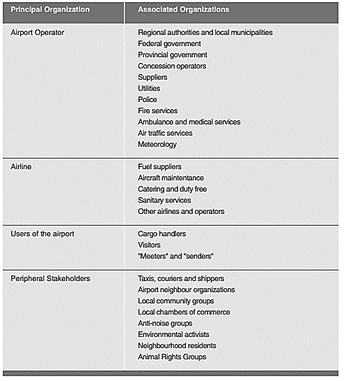
Figure 3: Examples of organizations affected by the operation of a large airport (MacKinnon et al., 2004, p. 101)
Smart Cities
It is not possible to define S3 of a transportation system without understanding the role and evolution of cities. Cities are places where a large number of people live and work. In addition, cities are hubs of government, commerce, and transportation. At the turn of the year 2000, there were 371 cities with 1 million inhabitants or more worldwide. By 2018, the number of cities with at least 1 million inhabitants had grown to 548, and in 2030, a projected 706 cities will have at least 1 million residents. The biggest cities in the world are often called megacities. These cities have more than 10 million inhabitants. Globally, the number of megacities is projected to rise from 33 in 2018 to 43 in 2030. The data are summarized Figure 4.
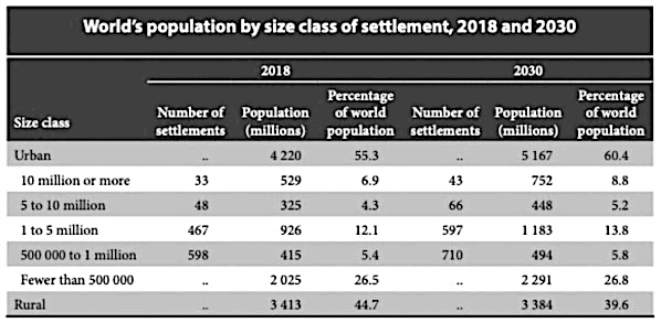
Figure 4: World’s population by size class of settlement, 2018 and 2030 (United Nations, 2018)
The purpose of a city is to provide the infrastructure necessary for people to live and work. The transportation system, buildings & housing, public space & recreation, power, communications, natural environment (e.g., air, soil, and rivers), water, food, sewage/waste, and government (e.g., governance, police, hospitals, and other bodies) compose the infrastructure. The infrastructure embodies the anatomy of the city. The infrastructure shall provide the capacity to serve the needs of the forecasted growing population. Smart cities try to optimize the use of the infrastructure intelligently.
Smart cities are associated with the fourth industrial revolution trend (Schwab, 2016). The term smart refers to digitization, enabled by cutting-edge technologies. As a result, smart cities refer to highly digitized cities equipped with cutting-edge technologies. According to Schwarz-Herion (2020), the cutting-edge technologies for modern cities are: 1) algorithms, 2) artificial intelligence, 3) autonomous vehicles, 4) big data, 5) blockchain, 6) CCTV (closed-circuit television) surveillance, 7) cloud computing, 8) drones, 9) 5G, 10) the internet of things (IoT), 11) LED light bulbs, 12) robots, 13) sensors, 14) smart grid, 15) smart meters, and 16) wearable devices.
The cutting-edge technology in smart cities seeks to improve the well-being of people. The improvement must be evident in the 3 pillars that affect our day-to-day journeys. These pillars are 1) economy, 2) environment, and 3) society and culture. Smiciklas, Prokop, Stano, and Sang (2017) define specific key performance indicators for smart cities.
Smart cities have the interactions of the (IoT), robotics, and people. Today, there are more connected devices (aka IoT) in the world than people coming in infinite forms, such as smart building technologies intended to monitor and manage energy usage, and connected cars expected to anticipate and avoid collisions (World Economic Forum, 2018, p. 18). By 2020, the number of IoT devices is forecasted to exceed 20 billion, enabled by continued technological advances and the plummeting costs of computing, storage, and connectivity. The IoT provides the ability of being accessed and controlled remotely, but it also has vulnerability to cyberattacks and the potential for security breaches that could cause serious harm in the ecosystem. The S3 of the aircraft is also vulnerable to such attacks.
Flying within smart cities means becoming part of their transportation system. An aircraft as part of the transportation city shall provide mobility demands for people and cargo. As a result, the operations of the aircrafts flying in smart cities shall align with the purpose of the city. Defining the meaning of such alignment is part of requirements engineering, which should respect the 3 pillars: 1) economy, 2) environment, and 3) society and culture. This article does not intend to fully understand the alignment. However, the successful business aircraft of the future must satisfy the need to align with the purpose of the served cities as system engineers evolve the design process.
Business Aircraft of the Future
It is not possible to define S3 of a transportation system without understanding the role of business aviation, the evolution of aircrafts and their technologies, and the organizational abilities to create the aircrafts. A business aircraft supports the activities in the business aviation sector. The sector concerns transport passengers or goods as an aid to the conduct of their business (International Business Aviation Council, 2019). Business-aircraft operations offer businesses the convenience of flexible scheduling and access to small airports (MacKinnon et al., 2004, p. 90).
The business aircraft of the future is an e-VTOL vehicle, which stands for electrical vertical takeoff and landing. The electrical component can power the aircraft in full (all electric) or complement a hybrid electric propulsion system with other types of engines (e.g., gas turbine) to provide the operation of the aircraft (Hardeman, 2020). Different engine types have powered aircrafts during history of civil aviation. Aircraft power plants were exclusively internal-combustion piston engines until the 1930s (MacKinnon et al., 2004, p. 75). Piston engines are categorized by cylinder configurations into radial engines and horizontally opposed engines (MacKinnon et al., 2004, p. 78). During the 30s, gas-turbine engines were developed, offering greater power while being lighter, more efficient and requiring less maintenance than piston engines (MacKinnon et al., 2004, p. 75). Gas turbine engines are categorized into turbojets, turbofans, turboprops, and turboshafts (MacKinnon et al., 2004, p. 78). Economic and environmental pressures have influenced gas-turbine efficiency developments since these engines first entered commercial operations: 1) reducing fuel consumption and environmental impacts, 2) thrust-to-weight ratios, 3) durability (including ability to cope with foreign-object ingestion, 4) controlling engine-operating parameters, 5) reducing noise-emission levels, and 6) reducing exhaust emissions (MacKinnon et al., 2004, p. 80). The electrical power system in an e-VTOL aircraft is probably the next generation propulsion system for the aircrafts of the future. Thus, this explains why the business aircraft of the future is an e-VTOL.
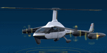
An e-VTOL business aircraft supports the smart traffic initiative to meet the sustainable goals expected from the smart cities of the future (Schwarz-Herion, 2020). The world e-VTOL aircraft directory that started in 2016 lists more than 220 products classified as vectored thrust (86), lift + cruise (30), Wingless – multicopter – (52), hover bikes/personal flying devices (41), and electric rotorcraft (17). Table 1 expands the classes of e-VTOL aircrafts and defines the classes of e-VTOL aircrafts with respective examples.
According to ICAO (2019b), e-VTOL aircrafts will be in service during the period 2020-2025. ICAO defines that e-VTOL aircrafts are expected to have seat capacities from 1 to 5, MTOWs between 450 and 2200 kg, and projected flight ranges from 16 to 300 km. These aircrafts could also consider electrical and hybrid power systems technologies. According to ICAO, these technologies have been researched for general aviation/recreational aircrafts, traditional sized business and regional aircrafts, and large commercial aircrafts.
The e-VTOL aircraft connects to its environment. The meaning of a connected e-VTOL can be inferred from the definition of a connected vehicle. A connected vehicle is a vehicle capable of safe, interoperable networked wireless communication between other vehicles, the infrastructure, and passengers’ personal communication devices to enable crash prevention and safety, mobility, and environmental benefits (Turnbull et al., 2017, p. 49). Hence, a connected e-VTOL business aircraft is an aircraft capable of safe, interoperable networked wireless communication between other aircrafts, the infrastructure (e.g., satellites, the air traffic management system, aircraft health systems monitoring, and inflight passenger business experience), and passengers’ personal communication devices (e.g., laptops and cellphones) to enable crash prevention and safety, mobility, and environmental benefits. Aerospace industry leaders such as Airbus (2019), Boeing (García, 2015), Honeywell (2019), and Southwest Airlines (Peterson, N/A) have acknowledged the role of connectivity in the future aircraft.
Table 1: e-VTOL: classes, definitions, and examples, constructed from The Electric VTOL News™ (2019b)
|
Class |
Definition |
Example |
Name |
|
Vectored thrust |
An e-VTOL aircraft that uses any of its thrusters for lift and cruise. |
|
Bell Nexus |
|
Lift + Cruise |
Completely independent thrusters used for cruise vs. for lift without any thrust vectoring. |
|
EmbraerX DreamMaker |
|
Wingless |
No thruster for cruise – only for lift. |
|
City-Airbus |
|
Hover bikes/personal flying devices |
The following single-person e-VTOL aircraft are considered to be in the general class of hover bikes or personal flying devices with the primary differentiation being that the pilot sits on a saddle or is standing, or something similar. All are multicopter-type wingless configurations. |
|
EosFlight |
|
Electric rotorcraft |
An e-VTOL aircraft that utilizes a helicopter frame. |
|
Jaunt Air Mobility |

Besides being connected to its environment, the e-VTOL aircraft must be autonomous to cope with the risk of pilot shortages. ICAO has defined an autonomous e-VTOL aircraft as an unmanned aircraft that does not allow pilot intervention in the management of the flight (National Research Council, 2014, p. 16). A fully autonomous aircraft would be able to operate independently within civil airspace, interacting with air traffic controllers and other pilots just as human pilots were on board and in command (National Research Council, 2014, p. 13). The National Research Council (NRC) indicates that an autonomous aircraft is the next evolution of current automatic systems such as autopilots and remotely piloted (non-autonomous) unmanned aircrafts. The electric VTOL News™ (2019a) lists 61 autonomous e-VTOL aircrafts.
An autonomous aircraft implies the ability of the system (often a machine) to perform tasks that involve dynamically executing a decision cycle in much the same fashion as a human (National Research Council, 2014, p. 14). The NRC suggests that there are different ways to represent the decision cycle, and the OODA loop is one of them. The loop stands for observe, orient, decide, and act. A description of actions in the loop are presented in Table 2. The loop can repeat several times in a second, for example 30 decision cycles per second. Interpreting the discussion by the NRC, autonomous aircrafts have the capability to accomplish a complete mission, which implies the autonomy of lower-level functions (e.g., using flight by wire control systems for stabilization and maneuvering the aircraft).
Table 2: OODA Loop: observe, orient, decide, and act, adapted from National Research Council (2014, p. 15)
|
OODA |
Description |
|
Observe |
The autonomous aircraft observes by sensing or acquiring information about the environment from other relevant sources. |
|
Orient |
After observing, the autonomous aircraft orients itself toward the task at hand. As a result, orientation infers a number of functions that can encompass information fusion, contextual interpretation, the integration of learned behaviors, and even inferences about future events. In the robotics community, this capability is known as perception. |
|
Decide |
The autonomous aircraft decides based on the task objectives and the results of observe and orient. |
|
Act |
The autonomous aircraft after making the decision is capable of implementing an appropriate action that accomplishes the task. Once the action is complete, the cycle repeats as the system observes the consequences of the action and the changes in the environment caused by other factors. |
A connected and autonomous aircraft integrates the capabilities of an autonomous vehicle and connectivity. The purpose of the integration is to make aviation safer, more secure, more sustainable, and easier to manage. This article does not provide the needed technologies and quantification of the previous capabilities, as systems engineers must evolve them as the design process evolves.
Global partnerships between organizations are at the core of bringing to life an autonomous and connected e-VTOL business aircraft. For instance, Bell Nexus is the result of engaging partners from across the globe, including Safran to build a hybrid-electric propulsion system; Thales to produce the flight control computers; Moog to make the actuation systems; EPS to innovate a battery system; and Garmin to provide the so-called nervous system to tie them all together (Bell flight, 2019b, p. 17). Rolls-Royce is looking for partnerships with airframers and electrical system providers to help commercialize its e-VTOL vehicle (Howard, 2018). Porsche and Boeing announced their joint exploration for the premium urban air mobility market (Vornehm, 2019). New competitors such as Larry Page – Google Cofounder – are also coming to make e-VTOL aircrafts a reality (Harris, 2018). As a result, creating the aircraft of the future is not the task of either traditional airframers, automotive manufacturers, or disruptive IT players; but rather the result of their potential collaboration to bring expertise from different actors.
The business aircraft of the future is the final element that conforms the context of operation to elicit a set of complete requirements. Section 3 defines the meaning of a complete set of requirements and its context.
Set of Complete Requirements
This section explains the meaning of the set of complete requirements and its context.
A complete set of requirements provides all of the stakeholders’ needs, and the associated constraints and conditions concerning the measurable qualitative or quantitative attribute that the system of interest (e.g., the aircraft of the future) must meet. When a system of interest satisfies a complete set of requirements, it means that all the stakeholders’ needs are met; therefore, a project is successful when it meets the needs and their associated elicited requirements.
The complete set of requirements for the aircraft of the future covers several entities and the relationships among them. These entities are stakeholders, smart airports, smart cities, the aircraft, and its life cycle. The stakeholders, smart airports, smart cities, and the aircraft were discussed in the previous section. The life cycle of the aircraft covers from conception to retirement. In particular, the concept stage, development, production, utilization, support (maintenance), and retirement define the life cycle of the aircraft. Given the entities, the complete set of requirements also includes the interactions between the entities. The interactions are defined by 10 classes: 1) Stakeholder – Stakeholder, 2) Stakeholder – Smart Airport, 3) Stakeholder – Smart City, 4) Stakeholder – Aircraft, 5) Stakeholder – Concept stage, 6) Stakeholder – Development, 7) Stakeholder – Production, 8) Stakeholder – Utilization, 9) Stakeholder – Support, and 10) Stakeholder – Retirement. The classes define the complete problem space to elicit the set of complete requirements for the aircraft of the future, starting from the most important view in any new product development project (stakeholders).
Now that the meaning of the set of complete requirements and its context has been introduced, the next question to answer is how to elicit the requirements. Section 4 presents the methodology to elicit a set of complete requirements, which answers the question how to elicit the requirements.
Methodology: ConOps, OpsCon, and Requirements
This article elicits a complete set of requirements following the guidance by the international standard ISO/IEC/IEEE 29148 (2018). Based on the interpretation of the standard, the methodology in Figure 5 is implemented in the article. According to Figure 5, a methodology to elicit the set of complete requirements shall consider the ConOps (i.e., Concept of Operations), the OpsCon (i.e., Operational Concept), and the requirements. They together provide confidence to organizations that their new products are the right solutions to satisfy the needs and expectations of the stakeholders.
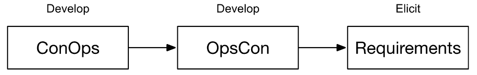
Figure 5: High level methodology to elicit the set of complete requirements
Top management (leaders) in an organization create the ConOps (INCOSE, 2015, p. 51). A ConOps can be implicit in the strategic plan of an organization. ISO/IEC/IEEE (2018) associates the ConOps with the business or mission analysis process. Therefore, developing the ConOps leads to defining the business or mission opportunity, characterizing the solution space, and determining potential solutions that could address a problem or take advantage of an opportunity.
The OpsCon follows the development of the ConOps for the potential solution. ISO/IEC/IEEE 29148 (2018) associates the OpsCon to the stakeholders’ needs and requirements definition process. Hence, developing the OpsCon results in the definition of the stakeholder requirements for a system that can provide the capabilities needed by users and other stakeholders in a defined environment.
The elicitation of the set of complete requirements follows the development of the ConOps and the OpsCon. ISO/IEC/IEEE (2018) associates the elicitation of the set of complete requirements to the system requirements definition process. Thus, eliciting the set of complete requirements results in the transformation of the stakeholder, user-oriented view of desired capabilities into a technical view of a solution that meets the operational needs of the user.
In synthesis, the activities in the previous three processes must be executed in order to elicit a complete set of requirements. Table 3 defines the activities for each process. ISO/IEC/IEEE (2018) provides further guidance about expected outcomes for each process and tasks for each activity.
Table : Detailed methodology to elicit the set of complete requirements: processes and activities constructed from (ISO/IEC/IEEE, 2018)
|
Process |
Activities |
|
Business or mission analysis process |
1. Prepare for business or mission analysis 2. Define the problem or opportunity space 3. Characterize the solution space 4. Evaluate alternative solution classes 5. Manage the business or mission analysis |
|
Stakeholder needs and requirements definition process |
1. Prepare for stakeholder needs and requirements definition 2. Define stakeholder needs 3. Develop the operational concept and other life cycle concepts 4. Transform stakeholder needs into stakeholder requirements 5. Analyze stakeholder requirements 6. Manage the stakeholder needs and requirements definition |
|
System requirements definition process |
1. Prepare for system requirements definition 2. Define system requirements 3. Analyze system requirements 4. Manage system requirements |
Set of Complete Requirements for the Business Aircraft of the Future
The purpose of this section is to elicit the set of complete requirements for the business aircraft of the future. To achieve this goal, the section introduces three outputs: 1) the developed ConOps, 2) the developed OpsCon, and 3) the elicited set of complete requirements. The remainder of the section provides each output.
The developed ConOps: business or mission analysis process
The developed ConOps addresses each activity for the business or mission analysis process in Table 3. Thus, the activities are expanded in the remaining of the section.
Prepare for business or mission analysis
Bringing to market a new e-VTOL business aircraft is a risky project with expected profitable products and services. The new aircraft must be more competitive than existing mobility solutions (e.g., helicopters, cars, public transportation and new solutions) in cities. In addition, the new aircraft must provide expected levels of safety, security, and sustainability for the envisioned smart cities of the future. The new aircraft must result in faster journeys and comfortable experiences than competing products within smart cities, from smart cities to smart airports, from smart airports to smart cities and near smart airports in order to delight its customers. The comfortable experiences arise from an easy autonomous flying (e.g., minimum training required), connection to all business support (e.g., internet, speakers, screens, drinks, goods compartment) during the journeys, and a quiet and a spacious high-end interior. Charging the aircraft must not interrupt the comfortable experiences. The saved time and comfort for customers shall translate to profit for the developing organizations and partners.
Define the problem or opportunity space
The aircraft shall be aesthetically appealing to customers driving luxurious (sport) cars (e.g., Bugatti Divo, Aston Martin Rapide A, Audi R8 performance series, Lamborghini Aventador series, Rolls-Royce Phantom, Bentley Mulsanne, BMW i8 Roadster, Tesla Roadster Founder Edition, Mercedes-Benz AMG One and Ferrari SF90 Stradale) affected by congestion and noisy helicopters in their day-to-day city journeys and trips from airports to cities or vice versa. The aircraft shall provide superior performances (e.g., range and speed), comfort for up to 4 passengers, cargo compartments, and faster journeys than these vehicles without compromising safety, security and sustainability in the transportation system.
The acquisition, operational, and maintenance costs of the aircraft should not be lower than luxurious cars but not higher than existing aircrafts. Potential investors expect the business aircraft of the future to yield the highest positive net present value (NPV) forecasted into a life cycle of 10 years, the highest return on investment (ROI) rate, the highest internal rate of return (IRR), the highest profitability index (PI) and the shortest payback period. In short, the business aircraft of the future must generate the greatest possible value to shareholders and investors using the latest technologies.
The aircraft must be electric and possess autonomous technologies to transport safely, securely, and sustainably the passengers and their cargo. The aircraft solution must consider the possibility of providing access to a priority flight path as a service. The systems engineering team must coordinate with regulators to create those services.
The systems engineering team must certify the aircraft faster than helicopters and traditional airplanes. The manufacture of the aircraft must compare to the cost and production timelines of luxurious cars. The aircraft shall enter into service by 2025, so manufacturing shall start by 2023. The aircraft must be maintained and charged without disrupting the daily operations of its customers longer than competing vehicles.
The aircraft shall be named The Disruptor. The Disruptor is the result of an explicit unnoticed combination between art, science, and technology. The Disruptor is all about providing pleasant emotions to the unique personalities of the customers. The form of The Disruptor arises after refining all the necessary functions to guarantee pleasant emotions to its customers. The Disruptor will embrace the principles of a circular economy (ICAO, 2019c, pp. 275-278) during its life and at retirement.
Characterize the solution space
The solution space of the aircraft must anticipate all the life cycle stages to be competitive. The stages include concept, development, production, utilization, support, and retirement. The systems engineering team must identify and consider all the stakeholders. The concept stage must prioritize all the stakeholders willing to share risk with experienced systems engineering execution and superior technological capabilities in autonomy and navigation, connectivity and interoperability, aerodynamics, materials, structure and fuselage, luxurious interiors and comfort, entertainment and business support, power systems (all-electric, electric and gas turbines, or other), electrical system, health management systems, manufacturing systems, certification, training services, and service infrastructures. The concept stage must define the selected partners, technologies, its design process and certification plan, a visual prototype of the e-VTOL business aircraft, and a simulated effective and efficient manufacturing system, operation, support, and retirement.
Evaluate alternative solution classes
The systems engineering team must provide evidence of the evaluation of multiple alternatives. The evaluation of each alternative must consider multiple criteria. Mandatory criteria are acquisition and operational costs, return on investment, safety, security, sustainability, range, speed, superior comfort, usability, saved time, manufacturability, and maintainability. Relevant stakeholders must agree and sign the approval of the evaluation method to rate each criterion, synthesize the evaluation process for each alternative and corresponding solution classes, and the decision-making process to choose a winning alternative. The evaluation of alternatives is applicable to all the life cycle stages.
Manage the business or mission analysis
The development of the ConOps or the business or mission analysis process implies iterations and recursions. As system engineers refine the concept stage, the descriptions in the previous sections can change. The activity of managing the business or mission analysis process demands that system engineers trace each refinement and change, and provide the key information items that they select as baselines as the result of the evaluation of alternatives. The iterations and recursions leading to refinements are beyond the scope of the article; however, readers interested in obtaining guidance in the activity can refer to the international standard (ISO/IEC/IEEE, 2018).
The developed OpsCon: stakeholder needs and requirements definition process
The developed OpsCon addresses each activity for the stakeholder needs and requirements definition process in Table 3. The activities are expanded in the remaining of the section.
Prepare for stakeholder needs and requirements definition
There are several stakeholders that have an interest in the e-VTOL business aircraft throughout its life cycle. System engineers can initiate the list of stakeholders by considering airport operators, airlines, users of the airport, and peripheral stakeholders, defined as principal organizations in Figure 3. System engineers can complete the list of stakeholders by considering other stakeholders discussed by Moir and Seabridge (2013, pp. 2, 8). The article doesn’t provide a complete list of stakeholders; nonetheless, it points out the great number of stakeholders that have an interest in the e-VTOL business aircraft. System engineers should establish the stakeholders’ intentions through consensus, so that the consented intentions become a common set of acceptable requirements. Methodologies and software tools record and manage this activity in order to validate that the aircraft satisfy the intention of the stakeholders.
Define stakeholder needs
The stakeholder needs for the e-VTOL business aircraft come from the context of use. The main context of use of the aircraft is flying within smart cities and near smart airports. System engineers associate other contexts of use to the life cycle stages that characterized the solution space. Passengers are the principal users in the main context of use of the aircraft. Through an app, passengers schedule a pick-up to the closest location. Passengers expect to embark the aircraft as quickly as getting on a competing vehicle. Passengers embark the aircraft at any time with any mood. Passengers complete the trip at the shortest possible time, but faster than any other vehicles. During the trip, passengers have a drink, listen to music, read, make a call, watch movies, transfer files, or just get relaxed in the aircraft. Passengers expect superior comfort, a pleasant trip to the destination, and to disembark the aircraft with a mood of joy and optimism. This is the journey of passengers travelling alone. The journey of passengers travelling with guests shall also be depicted. This is also the case for the journeys of the remaining stakeholders in their respective contexts of use. Complete needs come from all stakeholders and all contexts of use.
Develop the operational concept
System engineers need operational concepts for the concept, development, production, utilization, support, and retirement stages. Operational concepts provide scenarios for each stage and also for continuity between stages (e.g., from utilization to support and vice versa). Using the context of use as part of the utilization operational concept of the e-VTOL business aircraft, it all starts with the desire to transport a passenger and its cargo. Passengers who can use a smartphone, tablet or laptop, shall be able to schedule a flight and fly the aircraft anywhere in less than 30 minutes. Notoriously, system engineers can create a set of scenarios to understand the operation of the aircraft at four locations: the smart airport, from the smart airport to the smart city, in the smart city, and from the smart city to the airport. While flying in the locations (e.g., refer to Figure 1), passengers expect the aircraft to navigate and interoperate with any enabling system (e.g., air traffic control, telecommunication systems, regulations, other aircrafts, landing pads, connectivity services, and power grids). Several types of accidents could happen in the locations: customers’ injury through aircraft malfunction, collision with the ground, collision with an object, and general disintegration of the aircraft. An abrupt maneuver due to sensor failure or altered sensor readings is a type of aircraft malfunction that can injure customers. Loss of control, mechatronics failure, or the natural environment can cause a collision with the ground. Other objects in the air (e.g., aircrafts and birds) or other objects on the ground (e.g., other aircraft, people, and vehicles) can collide with the aircraft. Structure overload or fire/explosion in the electrical system can disintegrate the aircraft. Those accidents can occur when the aircraft serves its customers at the four locations. Accordingly, requirements must be written to mitigate the risk of the accidents such that passengers experience superior comfort and quicker rides compared to other vehicles in the industry, a pleasant trip to the destination, and disembarking with a mood of joy and optimism.
Transform stakeholder needs into stakeholder requirements
Stakeholder needs have been expressed since the business or mission analysis process. The needs are converted stakeholders’ requirements in this section. The stakeholder requirements are then allocated into a 10 classification of requirements. The employed classifications and allocated requirements are: Stakeholder – Stakeholder (10), Stakeholders – Smart Airport (3), Stakeholders – Smart Cities (4), Stakeholder – Aircraft (16), Stakeholder – Concept stage (4), Stakeholder – Development (5), Stakeholder – Production (5), Stakeholder – Utilization (6), Stakeholder – Support (3), and stakeholder – retirement (1). Each requirement in the classification is given a notation. The resulting stakeholder requirements are 57.
Stakeholder – Stakeholder (SS)
SS1 – Investors expect a profitable project, yielding the highest possible NPV in 10 years, ROI rate, IRR, PI, and the shortest payback period.
SS2 – Investors and acquirers expect that the acquisition and operational costs of the aircraft are lower than luxurious cars but not higher than existing aircrafts.
SS3 – Financial investors expect to provide capital & accept risk in order to gain a share of the expected profits.
SS4 – Knowledge, OEM, and supply chain investors expect to provide systems engineering execution experience, and superior technological capabilities in autonomy and navigation, connectivity and interoperability, aerodynamics, materials, structure and fuselage, luxurious interiors and comfort, entertainment and business support, power systems (all-electric, electric and gas turbines, or other), electrical systems, health management systems, manufacturing systems, certification, training services, and service infrastructures.
SS5 – Investors expect to create a team[1], conformed of business developers, systems engineers, and technical capabilities champions to lead the life cycle of the project.
SS6 – Investors and regulators expect the team to ensure that the aircraft and its technologies will satisfy all safety, security, and sustainability concerns from passengers, airport operators, airlines, users of the airport, city dwellers, investors, and others affected parties during the life of the aircraft.
SS7 – Investors expect that the team and regulators work together to provide access to a priority flight path as a service.
SS8 – Investors, the team, regulators and interested parties expect to agree and sign approval of the evaluation method to rate each criterion, synthesize the evaluation process for each alternative and corresponding solution classes, and the decision-making process to choose a winning alternative.
SS9 – Investors and related stakeholders expect the team to communicate to them the evaluation of multiple alternatives with respect to acquisition, operational, and maintenance costs, return on investment, safety, security, sustainability, range, speed, superior comfort, usability, saved time, manufacturability, and maintainability for all life cycle stages.
SS10 – Investors expect the team to employ methodologies and software tools to record and manage the establishment of stakeholders’ intentions into a common set of acceptable requirements, so that the validation that the aircraft satisfies the intentions of the stakeholders can be checked during the life cycle of the project.
Stakeholders – Smart Airport (SSA)
SSA1 – Passengers expect a pleasant and fast journey near smart airports, from smart airports to smart cities, and from smart cities to airports compared to rival solutions.
SSA2 – Passengers and its cargo expect to interoperate with smart airport space ten areas no less convenient than competing solutions when they are near the smart airport, leaving from the smart airport to the smart city, and arriving to the smart airport from the smart city.
SSA3 – Passengers, airport operators, airlines, users of the airport, city dwellers, investors, and others affected parties expect a safe, secure, and sustainable air transportation system to support the operations of the smart airports (see Figure 2).
Stakeholder – Smart City (SSC)
SSC1 – Passengers expect a pleasant and fast journey in smart cities, from smart cities to smart airports, and from smart airports to smart cities compared to rival solutions.
SSC2 – Passengers and its cargo expect to interoperate with the cutting-edge technologies of smart cities no less convenient than competing solutions when they are in the smart city, leaving from the smart city to the smart airport, and arriving to the smart city from the smart airport.
SSC3 – Passengers, city managers, airlines, city dwellers, investors, and others affected parties expect to comply with regulations for the serviced smart cities when the aircraft is in the smart city, leaving from the smart city to the smart airport, and arriving to the smart city from the smart airport.
SSC4 – Passengers, city managers, airlines, city dwellers, investors, and others affected parties expect a safe, secure, and sustainable transportation system to support the operations of the smart city: economy, environment, and society and culture.
Stakeholder – Aircraft (SA)
SA1 – Passengers, investors, the team, and the rest of affected stakeholders expect that the e-VTOL aircraft is autonomous, connected, safe, secure, and sustainable during all phases of flight (refer to Figure 6).
|
Preflight inspection |
Before engine start |
Engine start |
Before taxi |
Before takeoff |
After takeoff |
Cruise |
Descent |
Before landing |
After landing |
Engine shutdown and securing |
|
Preflight |
Flight |
Postflight |
||||||||
Figure 6: Phases of flight and their corresponding sub-phases, as interpreted from the U.S. Department of Transportation: Federal Aviation Administration (2012)
SA2 – Passengers expect the aircraft to have goods storage and seat capacity up to 4 passengers.
SA3 – Passengers expect a flight range from 16 to 300 km, to be further investigated depending on the locations to service.
SA4 – Passengers expect the aircraft to provide quicker journeys than competing vehicles.
SA5 – Passengers expect the aircraft to provide comfortable experiences during the phase of flight to delight customers.
SA6 – Passengers expect minimum training to fly the aircraft (e.g., a passenger who can use a smartphone, tablet or laptop, shall be able to fly the aircraft anywhere in less than 30 minutes).
SA7 – Regulators expect MTOW (maximum takeoff weight) between 450 and 2200 kg.
SA8 – Investors expect the team to propose an aircraft that is aesthetically appealing to potential customers driving luxurious (sport) cars (e.g., Bugatti Divo, Aston Martin Rapide A, Audi R8 performance series, Lamborghini Aventador series, Rolls-Royce Phantom, Bentley Mulsanne, BMW i8 Roadster, Tesla Roadster Founder Edition, Mercedes-Benz AMG One and Ferrari SF90 Stradale) affected by congestion and noisy helicopters in their day-to-day city journeys and trips from airports to cities or vice versa.
SA9 – Investors and the team expect the aircraft to bear the name The Disruptor.
SA10 – Investors and the team expect that the aircraft has an explicit unnoticed combination between art, science, and technology.
SA11 – Investors and the team expect the aircraft to provide pleasant emotions to the unique personalities of the customers.
SA12 – Investors and the team expect that aircraft embrace the principles of a circular economy during its life.
SA13 – Passengers schedule the pick-ups by the aircraft to the closest locations through an app.
SA14 – Passengers expect to embark the aircraft as quickly as getting on a competing vehicle during the 24 hours of a day with any mood.
SA15 – Passengers expect to have drinks, listen to music, read, call, watch movies, transfer files, or just get relaxed in the aircraft during the trip.
SA16 – Passengers expect superior comfort, a pleasant trip to the destination, and to disembark the aircraft with a mood of joy and optimism, so that they use the trip to remember the unique and valuable person they are without any inconvenience.
Stakeholder – Concept stage (SC)
SC1 – Investors and the team expect that the form of the aircraft arises after refining all the necessary functions to guarantee pleasant emotions to its customers.
SC2 – Investors and the team expect superior technological capabilities in autonomy and navigation, connectivity and interoperability, aerodynamics, materials, structure and fuselage, luxurious interiors and comfort, entertainment and business support, power systems (all-electric, electric and gas turbines, or other), electrical system, health management systems, manufacturing systems, certification, training services, and service infrastructures compared to rival solutions.
SC3 – Investors and the team expect during the concept stage to define the selected partners, technologies, its design process and certification plan; and create a visual prototype of the e-VTOL business aircraft, and a simulated effective and efficient manufacturing system, operation, support, and retirement.
SC4 – Investors and the team expect that the aircraft follows the principles of the circular economy during the concept stage.
Stakeholder – Development (SD)
SD1 – Investors expect that the aircraft enters into service by 2025.
SD2 – Investors expect that the team and regulators certify the aircraft faster than helicopters and traditional airplanes.
SD3 – Investors and the team expect that the aircraft follows the principles of the circular economy during development.
SD4 – Regulators expect the team to evaluate the consequence on passengers of potential accidents (customer injury through aircraft malfunction, collision with the ground, collision with an object, and general disintegration of the aircraft) at four locations during the phases of flight: the smart airport, from the smart airport to the smart city, in the smart city, and from the smart city to the smart airport.
SD5 – Investors expect the team to mitigate the risk of accidents such that passengers experience superior comfort and quicker rides compared to rival vehicles, a pleasant trip to the destination, and disembark the aircraft with a mood of joy and optimism.
Stakeholder – Production (SP)
SP1 – Investors expect that manufacturing of the aircraft starts by 2023.
SP2 – Investors expect that manufacturing of the aircraft scales up by 2025 at the aircraft entry into service such that the planned NPV, ROI rate, IRR, PI, and the payback period are met.
SP3 – Investors and the team expect that manufacturing of the aircraft must compare to the cost and production timelines of luxurious cars.
SP4 – Investors and the team expect that manufacturing delivers certified aircrafts.
SP5 – Investors and the team expect that the aircraft follows the principles of the circular economy during production.
Stakeholder – Utilization (SU)
SU1 – Passengers expect the aircraft is available when demanded.
SU2 – Acquirers and investors expect that the aircraft charges without disrupting the daily operations of its customers longer than competing vehicles.
SU3 – Investors and the team expect that the aircraft follows the principles of the circular economy during utilization.
SU4 – Passengers expect the aircraft to navigate and interoperate with any enabling system (e.g., air traffic control, telecommunication systems, regulations, other aircrafts, landing pads, connectivity services, and power grids) at four locations during the phases of flight: the smart airport, from the smart airport to the smart city, in the smart city, and from the smart city to the airport.
SU5 – Passengers, regulators, and affected stakeholders expect that the aircraft fly safely, securely, and sustainably during the phases of flight in smart cities, from the smart cities to the smart airport, and from the smart airports to the smart cities.
SU6 – Acquirers and investors expect that the costs of utilizing the aircraft compare to the costs of operating rival vehicles.
Stakeholder – Support (SSu)
SSu1 – Acquirers and investors expect that the aircraft is maintained without disrupting the daily operations of its customers.
SSu2 – Acquirers and investors expect that the aircraft is maintained with similar costs as competing vehicles.
SSu3 – Investors and the team expect that the aircraft follows the principles of the circular economy during support.
Stakeholder – Retirement (SR)
SR1 – Investors and the team expect that the aircraft follows the principles of the circular economy during retirement.
Analyze stakeholder requirements
The analysis of stakeholder requirements is a significant activity in the requirements engineering activity. In particular, this activity intends to study the feasibility, affordability, and the proper composition of the set of requirements as suggested in the standard. System engineers need one more iteration to convert the stakeholder requirements into qualifiable and quantifiable requirements, employing units and ranges (tolerances) as needed to avoid ambiguity. If system engineers fail to do this activity right, there is high probability that the project will delay, exceed costs, or stop in the future. However, the activity is beyond the scope of the article. Readers seeking guidance about the activity can refer to the standard.
Manage the stakeholder needs and requirements definition
The activity “transform stakeholder needs into stakeholder requirements” contains the last version of stakeholder requirement. This activity intends to control changes in the last version of requirements as the project progresses. The article does not cover such changes as they arise when system engineers evolve the design process. Readers seeking guidance about the activity can refer to the standard.
The elicited set of complete requirements: system requirements definition process
The elicited set of complete requirements address each activity for the system requirements definition process in Table 3. Thus, the activities are expanded in the remaining of the section.
Prepare for system requirements definition
The aircraft and the enabling systems along life of the aircraft are the systems of interest in the article; and the customer, cargo, smart cities, and smart airports are its environment. The main function of the aircraft is to provide people and their cargo an autonomous, connected, safe, secure, and sustainable flight within smart cities and smart airports along the aircraft movements. The operation of the aircraft starts by picking-up customers and/or cargo. If the operation starts in a smart city, the aircraft shall be able to interact with the customer through an application to be ready for embarking the customer and/or cargo at the nearest/selected pick-up location.
Assuming that the aircraft is not at the pick-up location when called, it shall fly from its current location to the pick-up one. To achieve this movement, the aircraft shall be able to communicate with other aircrafts in the smart city, comply with air traffic control rules, and have a feasible fly plan that can execute autonomously, safely, securely, and sustainably. Before the movement starts, the aircraft shall conduct the sub-phases during the preflight phase. The aircraft shall be capable of receiving any service expectations from the customer and adapt accordingly, for example, provide the desire temperature, light intensity, music ready to listen, ability to operate and share business files, etc. At this point, customers assume that the aircraft is charged enough (if it is all electric), which implies that the aircraft is able to interface with its source of power at the needed charging speed and without stressing the power source. When the aircraft arrives at the pick-up location, it shall be able to fit in the landing pad and to comply with any applicable regulations (e.g., maximum weight). If the landing pads are shareable with other aircrafts, the aircraft shall have a priority reservation mechanism in order to avoid making the customer to wait. The aircraft shall be able to manage all the necessary information sharing with the air traffic control network to access its priority reservation service.
Once the aircraft arrives at a pick-up location, customers shall be capable of loading any shape of cargo (e.g., rounded, squared, soft, solid, etc.) in the aircraft while also complying with the regulations. Customers shall load the aircraft as fast as loading the compartments of a car. When the aircraft embarks the customer, it shall read its moods. The aircraft shall adapt all its interior components to provide a pleasant and comfortable trip to the customer, so that the customer feels joy and optimism at disembarking. If the needed adaptation of the interior components contradicts the selected settings by the customer, the aircraft shall suggest and explain to the customer the needed adaptations so that the customer can understand the rationale of the suggestion and have the opportunity to accept changes to the settings. At this point, the aircraft shall be capable of complying with all preflight regulations.
The aircraft shall perform autonomously the flight phases faster than any other competing vehicle, but it shall also comply with all regulations and be connected with other aircrafts. The aircraft shall comply with all regulations when flying within smart cities, from a smart city to a smart airport, and from a smart airport to a smart city. The aircraft shall be able to manage possible stops from the embarking location to the final destination. During the flight phase, customers change their moods, get relaxed, and receive any required service (e.g., transfer files or watching movies) at the same speed as at home or at office. If the disembarking pad is shareable, the aircraft shall manage autonomously the reservation such that customers do not wait.
At disembarking, the customer may opt to share the agenda from its phone, laptop, or other devices with the aircraft such that it can schedule intelligently charging of its battery and conduct any maintenance task in order to be always available to the customer. Customers expect the aircraft to comply with any regulations with the landing pad at disembarking and to ensure that it is adequate to the customer needs. The aircraft shall end its operation by executing autonomously the sub-phases of the postflight phase.
The team shall demonstrate that there are enabling systems capable of supporting the operations of the aircraft at its boundaries with the customer, cargo, smart cities, and smart airports during the phases of flight. The team shall identify the interfaces between the aircraft and each boundary during the phases of flight in order to support the operations of the aircraft. In addition, the team shall define the interface properties and constraints (mechanical, electrical, mass, thermal, data, and procedural flows) in the next iterations of the requirements engineering task. The next iteration implies to define the functions at each boundary (e.g., aircraft cargo, aircraft-customer, aircraft-smart airport, aircraft-smart city) and respective performance for each phase of flight, such that the expected behavior of the aircraft (i.e., to fly safely, securely, and sustainably; but also, the team shall express the meaning of faster than any competing vehicle) in qualitative and quantitative terms at each boundary and at a whole.
Define system requirements (SySR)
The main function of the aircraft is to provide people and their cargo an autonomous, connected, safe, secure, and sustainable flight within smart cities, from smart cites to smart airports, from smart airports to smart cities, and near smart airports. To achieve this function, this section discusses the technologies that conform the aircraft and life cycle stages of the aircraft.
To achieve the major function of the aircraft, a navigation system and an automated flight control system of the aircraft shall execute the OODA loop (see Table 2) to direct the aircraft as intended by its passengers and regulators. The automated flight control system shall also communicate with other aircrafts, traffic control, and any other enabling system to fly. The health monitoring systems and power management system of the aircraft shall also feed their statuses to the automated flight control system so that the aircraft is capable to predict and assure that it will perform safely, securely, and sustainably its trip for the needed range.
The landing gear of the aircraft shall permit landing and take-off from all the possible locations in the smart cities of interest and smart airports in the trips. The airframe and its materials of the aircraft shall guarantee that it will resist all the encountered weather conditions, payloads, and loads during the trips; but they also facilitate flying with the lowest possible energy.
The interior components of the aircraft shall remain quiet and stable during the phases of flight so that the passengers experience a similar comfort as competing vehicles. The interior components shall read the mood of the passenger beginning with the pre-flight phase if demanded, so that the interior of the aircraft adapts automatically to change the mood.
The electrical system shall power all the electronics (navigation systems, automated flight control system, telecommunication devices, business multimedia, HVAC systems, internal and external lights, etc.) in the aircraft, such that the aircraft can fly safely, securely, and sustainably; but it also services the expectations of the customer. A battery or any other sustainable source of energy system shall supply the power to the electrical system and create the aerodynamic forces needed to fly the aircraft safely, securely, and sustainably.
The supply chain and manufacturing systems shall deliver aircrafts as fast and not more expensively than competing vehicles. The supply chain, manufacturing systems, and service centers shall be ready to make the aircraft available as needed for the customers when it is in service. The maintenance of the aircraft shall be as quick and expensive as for competing vehicles. Training for the aircraft maintenance personal shall not exceed the cost and time as for competing vehicles. Agreements shall be in place to retire the aircraft in accordance with the principles of the circular economy.
The team shall save the design, its development, its manufacturing blueprint, maintenance plan, and operation records of the aircraft for the whole life of the aircraft and beyond. The team shall also justify the remaining storage time beyond the life of the aircraft by a cost-benefit analysis and comply with any regulation. The life cycle cost of the aircraft shall be lower than competing vehicles, such that the aircraft has the right acquisition, operation, insurance, financial, and maintenance costs for the target acquirers.
System requirements arise from the main function of the aircraft, and they align with the stakeholder requirements and the functional boundaries. The remainder of this section aligns them using the classification employed for stakeholder requirements. The employed stakeholder requirements classifications, the 57 elicited stakeholder requirements, and the 101 allocated system requirements[2] are listed below. Table 4 to 13 break down the 101 system requirements respect to each stakeholder requirements class.
Stakeholder – Stakeholder (SS)
The class Stakeholder – Stakeholder elicited 10 stakeholder requirements. For these requirements, 11 system requirements were allocated (refer to Table 4). The allocated system requirements are detailed below.
Table 4: Allocation of system requirements into stakeholder requirements: Stakeholder – Stakeholder
|
Stakeholder – Stakeholder (SSA) |
SS1 |
SS2 |
SS3 |
SS4 |
SS5 |
SS6 |
SS7 |
SS8 |
SS9 |
SS10 |
|
System requirements |
1 |
1 |
1 |
2 |
1 |
1 |
1 |
1 |
1 |
1 |
SS1 – Investors expect a profitable project, yielding the highest possible NPV in 10 years, ROI rate, IRR, PI, and the shortest payback period.
- SS1 – SySR1 – The life cycle cost of the aircraft shall be lower than competing vehicles, such that the aircraft has the right acquisition, operation, insurance, financial, and maintenance costs for the target acquirers.
SS2 – Investors and acquirers expect that the acquisition and operational costs of the aircraft are lower than luxurious cars, but not higher than existing aircrafts.
- SS2 – SySR1 – The same as requirement SS1 – SySR1.
SS3 – Financial investors expect to provide capital and accept risk in order to gain a share of the expected profits.
- SS3 – SySR1 – The project shall deliver a variety of products (e.g., technology transfer to other industries), services (e.g., priority reservation mechanism), and systems (a differentiated aircraft) with de-risked revenues and profits.
- See also requirement SS1 – SySR1.
SS4 – Knowledge, OEM, and supply chain investors expect to provide systems engineering execution experience, and superior technological capabilities in autonomy and navigation, connectivity and interoperability, aerodynamics, materials, structure and fuselage, luxurious interiors and comfort, entertainment and business support, power systems (all-electric, electric and gas turbines, or other), electrical systems, health management systems, manufacturing systems, certification, training services, and service infrastructures.
- SS4 – SySR1 – Investors shall have systems engineering execution experience in aerospace or related industries.
- Investors shall have experience with MBSE to apply formal modeling to support system requirements, design, analysis, verification, and validation activities in aerospace or related industries.
- Investors shall have experience with traditional document-centric systems engineering in aerospace or related industries.
- SS4 – SySR2 – Investors shall have superior technological capabilities compared to rival products (e.g., cars, helicopters, airplanes, spacecrafts, and boats) in autonomy and navigation, connectivity and interoperability, aerodynamics, materials, structure and fuselage, luxurious interiors and comfort, entertainment and business support, power systems (all-electric, electric and gas turbines, or other), electrical systems, health management systems, manufacturing systems, certification, training services, and service infrastructures.
SS5 – Investors expect to create a team, conformed of business developers, systems engineers, and technical capabilities champions to lead the life cycle of the project.
- SS5 – SySR1 – Investors shall create a team, conformed of business developers, systems engineers, and technical capabilities champions to lead the life cycle of the project.
SS6 – Investors and regulators expect the team to ensure that the aircraft and its technologies will satisfy all safety, security, and sustainability concerns from passengers, airport operators, airlines, users of the airport, city dwellers, investors, and others affected parties during the life of the aircraft.
- SS6 – SySR1 – The team shall plan integration, verification, and validation to ensure that the aircraft and its technologies will satisfy all safety, security, and sustainability concerns from passengers, airport operators, airlines, users of the airport, city dwellers, investors, and others affected parties during the life of the aircraft.
SS7 – Investors expect that the team and regulators work together to provide access to a priority flight path as a service.
- SS7 – SySR1 – The team and regulators shall work together to provide access to a priority flight path as a service.
SS8 – Investors, the team, regulators and interested parties expect to agree and sign approval of the evaluation method to rate each criterion, synthesize the evaluation process for each alternative and corresponding solution classes, and the decision-making process to choose a winning alternative.
- SS8 – SySR1 – Investors, the team, regulators, and interested parties shall agree and sign approval of the evaluation method to rate each criterion, synthesize the evaluation process for each alternative and corresponding solution classes, and the decision-making process to choose a winning alternative.
- Investors, the team, regulators and interested parties shall consider as alternatives the complete aircraft, specific technologies (e.g., power systems, aerodynamics, and automatic flight control system), development strategy, manufacturing systems, certification, supply chain, services (operation, maintenance, and retirement), insurance, marketing and acquisition business models, and financing mechanism.
SS9 – Investors and related stakeholders expect the team to inform them of the evaluation of multiple alternatives respect to acquisition, operational, and maintenance costs, return on investment, safety, security, sustainability, range, speed, superior comfort, usability, saved time, manufacturability, and maintainability for all life cycle stages.
- SS9 – SySR1 – The team shall communicate the evaluation of multiple alternatives with respect to acquisition and operational costs, return on investment, safety, security, sustainability, range, speed, superior comfort, usability, saved time, manufacturability, and maintainability for all life cycle stages to the investors and related stakeholders.
SS10 – Investors expect the team to employ methodologies and software tools to record and manage the establishment of stakeholders’ intentions into a common set of acceptable requirements, so that the aircraft satisfies the intentions of the stakeholders and can be checked during the life cycle of the project.
- SS10 – SySR1 – The team shall employ methodologies and software tools to record and manage the establishment of stakeholders’ intentions into a common set of acceptable requirements, so that the validation that the aircraft satisfies the intentions of the stakeholders can be checked during the life cycle of the project.
- See also requirement SS4 – SySR1.
Stakeholders – Smart Airport (SSA)
The class Stakeholder – Smart Airport elicited 3 stakeholder requirements. For these requirements, four system requirements were allocated (refer to Table 5). The allocated system requirements are detailed below.
Table : Allocation of system requirements into stakeholder requirements: Stakeholders – Smart Airport
|
Stakeholders – Smart Airport (SSA) |
SSA1 |
SSA2 |
SSA3 |
|
System requirements |
2 |
1 |
1 |
SSA1 – Passengers expect a pleasant and fast journey near smart airports, from smart airports to smart cities, and from smart cities to airports compared to rival solutions.
- SSA1 – SysR1 – The aircraft shall comply with any demand from infrastructures and regulations in order to apply priority reservation mechanisms for landing pads near smart airports, from smart airports to smart cities, and from smart cities to smart airports, so that landing and taking-off do not delay the trip times and the journey is faster than compared rival solutions.
- SSA1 – SysR2 – The aircraft shall comply with any agreements from the team and regulators in order to use a priority flight path as a service, if requested by customers, when flying near smart airports, from smart airports to smart cities, and from smart cities to airports; so that the journey is faster than compared rival solutions.
SSA2 – Passengers and its cargo expect to interoperate with the smart airport space 10 areas no less convenient than competing solutions when they are near the smart airport, leaving from the smart airport to the smart city, and arriving to the smart airport from the smart city.
- SSA2 – SysR1 – The aircraft or its enabling systems shall enable the passengers and cargo to clear any regulation respect to the smart airport space 10 areas (refer to Section 2.1) in order to avoid delays in entering, staying, and leaving the smart airport proximity; so that the journey is faster than compared rival solutions.
SSA3 – Passengers, airport operators, airlines, users of the airport, city dwellers, investors, and others affected parties expect a safe, secure, and sustainable air transportation system to support the operations of the smart airports (e.g., Figure 2).
- SSA3 – SysR1 – The team shall demonstrate along the life cycle of the aircraft (i.e., concept stage, development, production, utilization, support, and retirement) to potential passengers, airport operators, airlines, users of the airport, city dwellers, investors, and others affected parties that the aircraft flies safely, securely, and sustainably in order to comply with all directives of a sustainable air transportation system in the operations of the smart aircraft.
Stakeholder – Smart City (SSC)
The class Stakeholder – Smart City elicited four stakeholder requirements. For these requirements, six system requirements were allocated (refer to Table 6). The allocated system requirements are detailed below.
Table 6: Allocation of system requirements into stakeholder requirements: Stakeholders – Smart City
|
Stakeholders – Smart City (SSC) |
SSC1 |
SSC2 |
SSC3 |
SSC4 |
|
System requirements |
2 |
2 |
1 |
1 |
SSC1 – Passengers expect a pleasant and fast journey in smart cities, from smart cities to smart airports, and from smart airports to smart cities compared to rival solutions.
- SSC1 – SysR1 – The aircraft shall comply with any demand from infrastructures and regulations in order to apply priority reservation mechanisms for landing pads in smart cities, from smart airports to smart cities, and from smart cities to smart airports, so that landing and taking-off do not delay the trip times and the journey is faster than compared rival solutions.
- SSC1 – SysR2 – The aircraft shall comply with any agreements from the team and regulators in order to use a priority flight path as a service, if requested by customers, when flying in smart cities, from smart airports to smart cities, and from smart cities to airports; so that the journey is faster than compared rival solutions.
SSC2 – Passengers and its cargo expect to interoperate with the cutting-edge technologies of smart cities no less convenient than competing solutions when they are in the smart city, leaving from the smart city to the smart airport, and arriving to the smart city from the smart airport.
- SSC2 – SysR1 – The aircraft or its enabling systems shall enable the passengers and cargo to interoperate with cutting-edge technologies in smart cities (refer to Section 2.2) in order to avoid delays; so that the journey is faster than compared rival solutions.
- SSC2 – SysR2 – The aircraft or its enabling systems shall enable the passengers and cargo to interoperate with cutting-edge technologies in smart cities (refer to Section 2.2) and provide a pleasant experience in the trip no less convenient than competing solutions.
SSC3 – Passengers, city managers, airlines, city dwellers, investors, and others affected parties expect to comply with regulations for the serviced smart cities when the aircraft is in the smart city, leaving from the smart city to the smart airport, and arriving to the smart city from the smart airport.
- SSC3 – SysR1 – The team shall demonstrate along the life cycle of the aircraft (i.e., concept stage, development, production, utilization, support, and retirement) to potential passengers, city managers, airlines, city dwellers, investors, and others affected parties that the aircraft complies with regulations for the serviced smart cities so that the aircraft flies safely, securely, and sustainably in the smart city, leaving from the smart city to the smart airport, and arriving to the smart city from the smart airport.
SSC4 – Passengers, city managers, airlines, city dwellers, investors, and others affected parties expect a safe, secure, and sustainable transportation system to support the operations of the smart city: economy, environment, and society and culture.
- SSC4 – SysR1 – The team shall demonstrate along the life cycle of the aircraft (i.e., concept stage, development, production, utilization, support, and retirement) to potential passengers, city managers, airlines, city dwellers, investors, and others affected parties that the aircraft flies safely, securely, and sustainably in order to comply with all directives of a sustainable transportation system to support the operations of the smart city: economy, environment, and society and culture.
Stakeholder – Aircraft (SA)
The class Stakeholder – Aircraft elicited eight stakeholder requirements. For these requirements, 29 system requirements were allocated (refer to Table 7). The allocated system requirements are detailed below.
Table 7: Allocation of system requirements into stakeholder requirements: Stakeholders – Aircraft
|
Stakeholders – Aircraft (SA) |
SA1 |
SA2 |
SA3 |
SA4 |
SA5 |
SA6 |
SA7 |
SA8 |
|
System requirements |
4 |
2 |
1 |
4 |
1 |
1 |
1 |
1 |
|
Stakeholders – Aircraft (SA) |
SA9 |
SA10 |
SA11 |
SA12 |
SA13 |
SA14 |
SA15 |
SA16 |
|
System requirements |
1 |
1 |
1 |
1 |
1 |
3 |
1 |
5 |
SA1 – Passengers, investors, the team, and the rest of affected stakeholders expect that the e-VTOL aircraft is autonomous, connected, safe, secure, and sustainable during all phases of flight (refer to Figure 6).
- SA1 – SysR1 – The aircraft shall be able to communicate with other aircrafts in the smart city, from the smart city to the smart airport, and from the smart airport to the smart city during the phases of flight, comply with air traffic control rules, and have a feasible fly plan that can execute autonomously, safely, securely, and sustainably.
- SA1 – SysR2 – The aircraft shall conduct the sub-phases during the preflight phase before the flight phase starts.
- SA1 – SysR3 – The aircraft shall conduct the sub-phases during the flight phase before the post-flight phase starts.
- SA1 – SysR4 – The aircraft shall conduct the sub-phases during the postflight phase after completing the flight phase and customers do no longer request the aircraft for service.
SA2 – Passengers expect the aircraft to have goods storage and seat capacity up to 4 passengers.
- SA2 – SysR1 – The aircraft shall be capable of loading any shape of cargo (e.g., rounded, squared, soft, solid, etc.) at the pick-up locations, while it also complies with applicable regulations.
- SA2 – SysR2 – The aircraft shall provide seat capacity up to 4 passengers.
SA3 – Passengers expect a flight range from 16 to 300 km, to be further investigated depending on the locations to service.
- SA3 – SySR1 – The aircraft shall have enough electrical energy or an alternative energy source to fly safely, securely, and sustainably a flight range from 16 to 300 km.
SA4 – Passengers expect the aircraft to provide quicker journeys than competing vehicles.
- SA4 – SySR1 – The aircraft shall fly autonomously from its current location to the pick-up one when called and it is not at the pick-up location.
- SA4 – SySR2 – Passengers shall load the aircraft as fast as loading the compartments (e.g., the trunk) of a car.
- SA4 – SySR3 – The aircraft shall perform autonomously all the flight phases faster than any other competing vehicle, but it shall also comply with all regulations and be connected with other aircrafts.
- SA4 – SySR4 – The aircraft shall manage autonomously a priority reservation mechanism such that customers do not wait at embarking, flying, and disembarking.
SA5 – Passengers expect the aircraft to provide comfortable experiences during the phase of flight to delight customers.
- SA5 – SysR1 – The aircraft shall be capable of receiving any service expectations from the customer and adapt accordingly, for example, provide the desire temperature, light intensity, music ready to listen, ability to operate and share business files, etc.
SA6 – Passengers expect minimum training to fly the aircraft (e.g., a passenger who can use a smartphone, tablet or laptop, shall be able to be trained to fly the aircraft anywhere in less than 30 minutes).
- SA6 – SysR1 – The team shall demonstrate to potential passengers that it takes less than 30 minutes to train a person who can use a smartphone, tablet, or laptop to fly safely the aircraft to anywhere.
SA7 – Regulators expect MTOW (maximum takeoff weight) between 450 and 2200 kg.
- SA7 – SySR1 – The aircraft shall comply with any applicable regulations (e.g., MTOW) at pick-up locations.
SA8 – Investors expect the team to propose an aircraft that is aesthetically appealing to potential customers driving luxurious (sport) cars (e.g., Bugatti Divo, Aston Martin Rapide A, Audi R8 performance series, Lamborghini Aventador series, Rolls-Royce Phantom, Bentley Mulsanne, BMW i8 Roadster, Tesla Roadster Founder Edition, Mercedes-Benz AMG One and Ferrari SF90 Stradale) affected by congestion and noisy helicopters in their day-to-day city journeys and trips from airports to cities or vice versa.
- SA8 – SySR1 – The team shall propose and demonstrate that the aircraft is aesthetically appealing to potential customers driving luxurious (sport) cars (e.g., Bugatti Divo, Aston Martin Rapide A, Audi R8 performance series, Lamborghini Aventador series, Rolls-Royce Phantom, Bentley Mulsanne, BMW i8 Roadster, Tesla Roadster Founder Edition, Mercedes-Benz AMG One and Ferrari SF90 Stradale) affected by congestion and noisy helicopters in their day-to-day city journeys and trips from airports to cities or vice versa.
SA9 – Investors and the team expect the aircraft to bear the name The Disruptor.
- SA9 – SySR1 – The aircraft shall bear the name The Disruptor.
SA10 – Investors and the team expect that the aircraft has an explicit unnoticed combination between art, science, and technology.
- SA10 – SySR1 – The team shall demonstrate to investors that the aircraft combines art, science, and technology.
SA11 – Investors and the team expect the aircraft to provide pleasant emotions to the unique personalities of the customers.
- SA11 – SySR1 – The team shall demonstrate to investors that aircraft provide pleasant emotions to the unique personalities of the customers (e.g., passengers, regulators, maintainers, and disposers).
SA12 – Investors and the team expect that aircraft embrace the principles of a circular economy during its life.
- SA12 – SySR1 – The team shall demonstrate to investors that the aircraft embrace the principles of a circular economy during its life (concept stage, development, production, utilization, maintenance, and retirement).
SA13 – Passengers through an app schedule the pick-ups by the aircraft to the closest locations.
- SA13 – SySR1 – The aircraft shall be able to interact with the customer through an application to be ready for embarking the customer and/or cargo at the nearest/selected pick-up location.
SA14 – Passengers expect to embark the aircraft as quickly as getting on a competing vehicle during the 24 hours of a day with any mood.
- SA14 – SySR1 – The aircraft shall be available at demand during the 24 hours of a day.
- SA14 – SySR2 – The team shall demonstrate that aircraft can be embarked as quickly as getting on a competing vehicle at any time of the day.
- SA14 – SySR3 – The aircraft shall read and adapt to all possible passengers’ moods at embarking.
SA15 – Passengers expect to have drinks, listen to music, read, call, watch movies, transfer files, or just get relaxed in the aircraft during the trip.
- SA15 – SySR1 – Passengers expect to change the aircraft’s moods, get relaxed, and receive any required service (e.g., transfer files or watching movies) at the same speed as at home or office during the flight phase.
SA16 – Passengers expect superior comfort, a pleasant trip to the destination, and to disembark the aircraft with a mood of joy and optimism.
- SA16 – SySR1 – The aircraft (e.g., a face-recognition system, and an intelligent behavior detection system) shall identify the mood of customers while scheduling a trip or embarking the aircraft.
- SA16 – SySR2 – The interior components of the aircraft shall read the mood of the passenger while scheduling a trip or embarking, so that the interior of the aircraft adapts automatically to change any initial mood into a mood of joy and optimism at disembarking with the ultimate goal of reminding a passenger the unique valuable person s/he is without any inconvenience.
- SA16 – SySR3 – The aircraft shall allow the customer to control the desire settings for the interior component.
- SA16 – SySR4 – The aircraft shall suggest and explain to the customer the ideal interior component settings when they contradict with the selected ones by the customer, so that the customer can understand the rationale of the suggestion and s/he accepts to change the settings to obtain a pleasant and comfortable trip that guarantees a disembarking mood of joy and optimism.
- SA16 – SySR4 – The interior components of the aircraft shall remain quiet and stable during the phases of flight so that the passengers experience more pleasant and comfortable trips than competing vehicles.
- SA16 – SySR5 – The aircraft shall be able to manage possible stops from the embarking location to the final destination.
Stakeholder – Concept stage (SC)
The class Stakeholder – Concept stage elicited four stakeholder requirements. For these requirements, seven system requirements were allocated (refer to Table 8). The allocated system requirements are detailed below.
Table 8: Allocation of system requirements into stakeholder requirements: Stakeholders – Concept stage
|
Stakeholders – Concept stage (SC) |
SC1 |
SC2 |
SC3 |
SC4 |
|
System requirements |
1 |
1 |
3 |
2 |
SC1 – Investors and the team expect that the form of the aircraft arises after refining all the necessary functions to guarantee pleasant emotions to its customers.
- SC1 – SySR1 – The team shall demonstrate to investors that the form of the aircraft arose after refining all the necessary functions to guarantee pleasant emotions to its customers during the phases of flight within smart cities, from smart cities to smart airports, from smart airports to smart cities, and near smart airports.
SC2 – Investors and the team expect superior technological capabilities in autonomy and navigation, connectivity and interoperability, aerodynamics, materials, structure and fuselage, luxurious interiors and comfort, entertainment and business support, power systems (all-electric, electric and gas turbines, or other), electrical system, health management systems, manufacturing systems, certification, training services, and service infrastructures compared to rival solutions.
- SC2 – SySR1 – The team shall demonstrate to investors that the aircraft provides superior but feasible technological capabilities in autonomy and navigation, connectivity and interoperability, aerodynamics, materials, structure and fuselage, luxurious interiors and comfort, entertainment and business support, power systems (all-electric, electric and gas turbines, or other), electrical system, health management systems, manufacturing systems, certification, training services, and service infrastructures compared to rival solutions.
SC3 – Investors and the team expect during the concept stage to define the selected partners, technologies, its design process and certification plan; and create a visual prototype of the e-VTOL business aircraft, and a simulated effective and efficient manufacturing system, operation, support, and retirement.
- SC3 – SySR1 – The team shall save the design, its development, its manufacturing blueprint, certification plan and verification methods, maintenance plan, and operation records of the aircraft for the whole life of the aircraft and beyond. The team shall also justify the remaining storage time beyond the life of the aircraft by a cost-benefit analysis and comply with any regulation.
- SC3 – SySR2 – The team and investors shall define the selected partners, the technologies, and the design process and certification plan for the e-VTOL business aircraft during the concept stage.
- SC3 – SySR3 – The team shall demonstrate to investors a visual prototype of the e-VTOL business aircraft, and a simulated effective and efficient manufacturing system, operation, support, and retirement.
SC4 – Investors and the team expect that the aircraft follows the principles of the circular economy during the concept stage.
- SC4 – SySR1 – The team shall demonstrate to investors that the aircraft embrace the principles of the circular economy during the concept stage.
- SC4 – SySR2 – The concept stage of the aircraft shall comply with agreements applying the principles of the circular economy, developed in consensus by investors, team, regulators, and affected stakeholders.
Stakeholder – Development (SD)
The class Stakeholder – Development elicited five stakeholder requirements. For these requirements, eight system requirements were allocated (refer to Table 9). The allocated system requirements are detailed below.
Table 9: Allocation of system requirements into stakeholder requirements: Stakeholders – Development
|
Stakeholders – Development (SD) |
SD1 |
SD2 |
SD3 |
SD4 |
SD5 |
|
System requirements |
2 |
1 |
2 |
1 |
2 |
SD1 – Investors expect that the aircraft enters into service by 2025.
- SD1 – SySR1 – The team shall demonstrate to investors a de-risked plan to assure that the aircraft enters into service by 2025.
- SD1 – SySR2 – The aircraft shall enter into service by 2025.
- See also SP1 – SysR1
SD2 – Investors expect that the team and regulators certify the aircraft faster than helicopters and traditional airplanes.
- SD2 – SySR1 – The team shall work together with investors and regulators to create a certification plan for the aircraft in order to assure the entry into service by 2025.
- The certification plan shall ensure compliance with applicable regulations and applicable safety, security, and sustainability requirements.
- The certification plan shall assure faster certification than helicopters and traditional airplanes.
SD3 – Investors and the team expect that the aircraft follows the principles of the circular economy during development.
- SD3 – SySR1 – The team shall demonstrate to investors that the aircraft embrace the principles of the circular economy during the development.
- SD3 – SySR2 – The development of the aircraft shall comply with agreements applying the principles of the circular economy, developed in consensus by investors, team, regulators, and affected stakeholders.
SD4 – Regulators expect the team to evaluate the consequences on passengers of potential accidents (customer injury through aircraft malfunction, collision with the ground, collision with an object, and general disintegration of the aircraft) at four locations during the phases of flight: the smart airport, from the smart airport to the smart city, in the smart city, and from the smart city to the smart airport.
- SD4 – SySR1 – The team shall demonstrate to regulators the evaluation of consequences on passengers of potential accidents (customer injury through aircraft malfunction, collision with the ground, collision with an object, and general disintegration of the aircraft) at four locations during the phases of flight: the smart airport, from the smart airport to the smart city, in the smart city, and from the smart city to the smart airport.
SD5 – Investors expect the team to mitigate the risk of accidents such that passengers experience superior comfort and quicker rides compared to rival vehicles, a pleasant trip to the destination, and disembark the aircraft with a mood of joy and optimism.
- SD5 – SySR1 – The team shall define all the possible risks of accidents.
- The team shall include as one part of all the possible risks of accidents all the recorded incidents for helicopters and airplanes.
- The team shall obtain approval from regulators and investors about all the defined possible risks of accidents.
- SD5 – SySR2 – The team shall demonstrate that passengers experience superior comfort and quicker rides compared to other rival vehicles, a pleasant trip to the destination, and disembark the aircraft with a mood of joy and optimism under the present of all the defined risks in SD5 – SySR1.
Stakeholder – Production (SP)
The class Stakeholder – Production elicited five stakeholder requirements. For these requirements, nine system requirements were allocated (refer to Table 10). The allocated system requirements are detailed below.
Table 10: Allocation of system requirements into stakeholder requirements: Stakeholders – Production
|
Stakeholders – Production (SP) |
SP1 |
SP2 |
SP3 |
SP4 |
SP5 |
|
System requirements |
2 |
1 |
1 |
3 |
2 |
SP1 – Investors expect that manufacturing of the aircraft starts by 2023.
- SP1 – SySR1 – The team shall demonstrate to investors a de-risked plan to assure that manufacturing of the aircrafts starts by 2023, so that the expected entry into service by 2025 is achieved.
- Manufacturing by 2023 implies readiness of the production system and supply chain to fabricate aircrafts (one or more) for certification purposes.
- SP1 – SySR2 – The first aircraft shall enter manufacturing by 2023.
SP2 – Investors expect that manufacturing of the aircraft scales up by 2025 at the aircraft entry into service such that the planned NPV, ROI rate, IRR, PI, and the payback period are met.
- SP2 – SySR1 – The team shall demonstrate to investors a de-risked plan to assure that manufacturing of the aircrafts scales up by 2025 at the aircraft entry into service such that the planned NPV, ROI rate, IRR, PI, and the payback period are met.
SP3 – Investors and the team expect that manufacturing the aircraft must compare to the cost and production timelines of luxurious cars.
- SP3 – SySR1 – The supply chain and manufacturing systems shall deliver aircrafts as fast and not more expensive than competing vehicles.
SP4 – Investors, regulators, and the team expect that manufacturing delivers certified aircrafts.
- SP3 – SySR1 – The team shall certify the production system with regulators.
- SP3 – SySR2 – The team shall comply with the certified production system each time during manufacturing.
- SP3 – SySR3 – The team shall record the compliance evidence each time during manufacturing.
SP5 – Investors and the team expect that the aircraft follows the principles of the circular economy during production.
- SP4 – SySR1 – The team shall demonstrate to investors that the aircraft embrace the principles of the circular economy during production.
- SP4 – SySR2 – The production of the aircraft shall comply with agreements applying the principles of the circular economy, developed in consensus by investors, team, regulators, and affected stakeholders.
Stakeholder – Utilization (SU)
The class Stakeholder – Utilization elicited six stakeholder requirements. For these requirements, 18 system requirements were allocated (refer to Table 11). The allocated system requirements are detailed below.
Table 11: Allocation of system requirements into stakeholder requirements: Stakeholders – Utilization
|
Stakeholders – Utilization (SU) |
SU1 |
SU2 |
SU3 |
SU4 |
SU5 |
SU6 |
|
System requirements |
2 |
1 |
2 |
7 |
5 |
1 |
SU1 – Passengers expect the aircraft is available when demanded.
- SU1 – SySR1 – The aircraft shall have priority in a reservation mechanism in order to avoid making the customer wait when the landing pads at the pick-up, intermediate, and destination locations are shareable with other aircrafts.
- SU2 – SySR2 – The aircraft can read the passengers’ agenda from its phone, laptop, or other devices while scheduling the trip, embarking, flying, and disembarking such that the aircraft can schedule intelligently charging its battery and conduct any maintenance task in order to be always available to the customer.
SU2 – Acquirers and investors expect that the aircraft charges without disrupting the daily operations of its customers longer than competing vehicles.
- SU2 – SySR1 – The aircraft shall be able to interface with its source of power at the needed charging or fueling speed and without stressing the power source.
SU3 – Investors and the team expect that the aircraft follows the principles of the circular economy during utilization.
- SU3 – SySR1 – The team shall demonstrate to investors that the aircraft embrace the principles of the circular economy during utilization.
- SU3 – SySR2 – The utilization of the aircraft shall comply with agreements applying the principles of the circular economy, developed in consensus by investors, team, regulators, and affected stakeholders.
SU4 – Passengers expect the aircraft to navigate and interoperate with any enabling system (e.g., air traffic control, telecommunication systems, regulations, other aircrafts, landing pads, connectivity services, and power grids) at 4 locations during the phases of flight: the smart airport, from the smart airport to the smart city, in the smart city, and from the smart city to the airport.
- SU4 – SySR1 – A navigation system and an automated flight control system of the aircraft shall execute the OODA loop, see Table 2, to direct the aircraft as intended by its passengers and regulators.
- SU4 – SySR2 – The automated flight control system of the aircraft shall communicate with other aircrafts, air traffic control, and any other enabling system to fly safely, securely, and sustainably.
- SU4 – SySR3 – The landing gear of the aircraft shall permit to land and take-off from all the possible locations in the smart cities of interest and smart airports in the trips.
- SU4 – SySR4 – The aircraft shall be able to manage all the necessary information sharing with the air traffic control network to access its priority reservation service during the phases of flight.
- SU4 – SySR5 – The aircraft shall comply with any regulation and its information sharing needs during the phase of flight within smart cities, from a smart city to a smart airport, and from a smart airport to a smart city.
- SU4 – SySR6 – The team shall demonstrate that there are enabling systems capable to support the operations of the aircraft at its boundaries with the customer, cargo, smart cities, and smart airports during the phases of flight.
- SU4 – SySR7 – The team shall identify the interfaces between the aircraft and each boundary during the phases of flight to support the operations of the aircraft.
- The team shall define the interfaces properties and constraints (mechanical, electrical, mass, thermal, data, and procedural flows).
SU5 – Passengers, regulators, and affected stakeholders expect that the aircraft fly safely, securely, and sustainably during the phases of flight in smart cities, from smart cities to smart airport, and from smart airports to smart cities.
- SU5 – SySR1 – A battery or any other sustainable source of energy system shall supply the power to the electrical system and create the aerodynamic forces needed to fly safely, securely, and sustainably the aircraft.
- SU5 – SySR2 – The electrical system shall power all the electronics (navigation systems, automated flight control system, telecommunication devices, business multimedia, HVAC systems, internal and external lights, etc.) in the aircraft, such that the aircraft can fly safely, securely, and sustainably; but it also services the expectations of the customer.
- SU5 – SySR3 – The airframe and its materials of the aircraft shall guarantee that it will resist all the encounter weather conditions, payloads, and loads during the trips; but they also facilitate to fly with the lowest possible energy.
- SU5 – SySR4 – The health monitoring system and power management system of the aircraft shall also feed their statuses to the automated flight control system, so that the aircraft is capable to predict and assure that it will perform safely, securely, and sustainably its trip for the needed range.
- SU5 – SySR5 – The aircraft shall be capable of complying with all preflight, flight, and post flight regulations when flying within smart cities, from a smart city to a smart airport, and from a smart airport to a smart city.
SU6 – Acquirers and investors expect that the costs of utilizing the aircraft compares to the costs of operating rival vehicles.
- SU6 – SysR1 – The team shall demonstrate to investors and acquirers that the cost to utilize the aircraft does not exceed the cost of operating competing vehicles.
Stakeholder – Support (SSu)
The class Stakeholder – Support elicited three stakeholder requirements. For these requirements, seven system requirements were allocated (refer to Table 12). The allocated system requirements are detailed below.
Table 12: Allocation of system requirements into stakeholder requirements: Stakeholders – Support
|
Stakeholders – Support (SSu) |
SSu1 |
SSu2 |
SSu3 |
|
System requirements |
3 |
2 |
2 |
SSu1 – Acquirers and investors expect that the aircraft is maintained without disrupting the daily operations of its customers.
- SSu1 – SySR 1 – The maintenance of the aircraft shall be as quick and cost the same as for competing vehicles.
- SSu1 – SySR 2 – The supply chain, manufacturing systems, and service centers shall be ready to make the aircraft available as needed for the customers when it is in service.
- SSu3 – SySR 3 – The team shall demonstrate to regulators and investigators that the aircraft is certifiable after each maintenance if needed.
SSu2 – Acquirers and investors expect that the aircraft is maintained with similar costs as competing vehicles.
- SSu2 – SySR 1 – Training for the aircraft maintenance personal shall not exceed the cost and time as for competing vehicles.
- SSu2 – SySR 2 – The team shall demonstrate to investors and acquirers that the cost to maintain the aircraft does not exceed the cost of maintaining competing vehicles.
SSu3 – Investors and the team expect that the aircraft follows the principles of the circular economy during support.
- SSu3 – SySR1 – The team shall demonstrate to investors that the aircraft embrace the principles of the circular economy during support.
- SSu3 – SySR2 – The support of the aircraft shall comply with agreements applying the principles of the circular economy, developed in consensus by investors, team, regulators, and affected stakeholders.
Stakeholder – Retirement (SR)
The class Stakeholder – Retirement elicited one stakeholder requirement. For this requirement, two system requirements were allocated (refer to Table 13). The allocated system requirements are detailed below.
Table 13: Allocation of system requirements into stakeholder requirements: Stakeholders – Retirement
|
Stakeholders – Retirement (SR) |
SR1 |
|
System requirements |
2 |
SR1 – Investors and the team expect that the aircraft follows the principles of the circular economy during retirement.
- SR1 – SySR1 – The team shall demonstrate to investors that the aircraft embrace the principles of the circular economy during retirement.
- SR2 – SySR1 – The retirement of the aircraft shall comply with agreements applying the principles of the circular economy, developed in consensus by investors, team, regulators, and affected stakeholders.
Analyze system requirements
The analysis of system requirements is a significant activity in the requirements engineering activity. In particular, this activity intends to study the feasibility, affordability and the proper composition of the set of requirements as suggested in the standard. System engineers need one more iteration to convert the system requirements into qualifiable and quantifiable requirements, employing units and ranges (tolerances) as needed to avoid ambiguity. If system engineers fail to do this activity properly, there is a high probability that the project will delay, exceed costs, or stop in the future. However, the activity is beyond the scope of the article. Readers seeking guidance about the activity can refer to the standard.
Manage system requirements
The activity “define system requirements (SySR)” contains the last version of system requirements in the article. This activity intends to control changes in the last version of requirements as the project progresses. The article does not cover such changes as they arise when system engineers evolve the design process. Readers seeking guidance about the activity can refer to the standard.
Comparison with other methodologies
The article employed text-based requirements. The reality of projects has proven that text-based requirements are the most effective form of communication among stakeholders. Text-based requirements offer several advantages compared to model-centric requirements. Such advantages are: facilitating communication with non-technical readers (e.g., lawyers, marketing, acquirers, administrators), power of expression of both functional and non-functional requirements, accessibility respect to software tools, definition of requirements attributes, creation of contracts, and system verification and validation (Wheatcraft, 2019).
Future work in the subject plans to use MBSE to model the set of complete requirements. This work will help to understand how text-based requirements and MBSE complement each other. In addition, the work will discover some limitations of MBSE in eliciting a complete set of requirements. Researchers can use the limitations to track the efforts and expected updates in SysML v2 (Systems Modeling Language) planned to support MBSE (Towers, 2020). Arcadia and Capella (Bonnet, Voirin, & Navas, 2019) are an alternative for comparing and understanding the limitations.
Summary and Conclusions
This article has presented the elicitation of a complete set of requirements for the business aircraft of the future. The complete set of requirements is vast, encompassing stakeholders, the aircraft, its enabling systems, the context of operation, and the life cycle of the aircraft. The article followed guidance from the international standard ISO/IEC/IEEE 29148:(2018) to elicit the complete set of requirements.
The complete set of requirements consists of 57 stakeholder requirements and their associated 101 system requirements. Both types of requirements were classified into 10 classes respectively: Stakeholder – Stakeholder (10, 11)[3], Stakeholder – Smart Airport (3, 4), Stakeholder – Smart City (4, 6), Stakeholder – Aircraft (16, 29), Stakeholder – Concept stage (4, 7), Stakeholder – Development (5, 8), Stakeholder – Production (5, 9), Stakeholder – Utilization (6, 18), Stakeholder – Support (3, 7), and Stakeholder – Retirement (1, 2). The classes assure that the article considered the complete problem space to system engineer the aircraft of the future; thus, it guarantees that the set of requirements is complete.
The complete set of requirements provides the foundation to: 1) facilitate the conversation in the systems engineering community concerning eliciting complete sets of requirements in the aerospace sector using traditional text-based requirements; 2) utilize the set of requirements to practice the attributes and characteristics of well-formed set of requirements specified in the standard; and 3) use the set of requirements as a baseline to understand the scope of MBSE in the elicitation of complete set of requirements in the aerospace sector.
List of Acronyms and Abbreviations Used in this Paper
Acronym Explanation
ConOps Concept of Operations
e-VTOL Electrical Vertical Take-Off and Landing
HVAC Heating, Ventilation, and Air Conditioning
IATA International Air Transport Association
ICAO International Civil Aviation Organization
INCOSE International Council on Systems Engineering
MBSE Model-based Systems Engineering
OODA Observe, Orient, Decide, and Act
OpsCon Operational Concept
S3 Safety, Security and Sustainability
SysML Systems Modeling Language
SA Stakeholder – Aircraft
SC Stakeholder – Concept Stage
SD Stakeholder – Development
SP Stakeholder – Production
SR Stakeholder – Retirement
SS Stakeholder – Stakeholder
SSA Stakeholder – Smart Airport
SSC Stakeholder – Smart City
SSu Stakeholder – Support
SU Stakeholder – Utilization
SySR System requirements
Acknowledgements
My thanks go to Dr. Ralph Young for his encouragement to write this article. Without his encouragement, the ideas in the article would have not been written.
References
Airbus. (2019). Connectivity: Connecting to the digital world anywhere. Retrieved from https://www.airbus.com/innovation/future-technology/connectivity.html
Bell flight. (2019a). Bell Nexus. Retrieved from https://www.bellflight.com/products/bell-nexus
Bell flight. (2019b). Special report: on-demand mobility and tomorrow’s smart cities. Retrieved from https://www.verticalcentury.com/182847-special-report-on-demand-mobility-and-tomorrow-s-smart-cities
Bonnet, S., Voirin, J.-L., & Navas, J. (2019). Augmenting Requirements with Models to Improve the Articulation between System Engineering Levels and Optimize V&V Practices. Systems Engineering Newsletter, 83. Retrieved from https://www.ppi-int.com/ppisyen83/#featurearticle
ciena. (2019). How does a smart city get smarter? Retrieved from https://media.ciena.com/documents/CN_CorpAdaptNetwork_InfoIllustration_R5.2.pdf
Flyvbjerg, B. (2014). What You Should Know About Megaprojects and Why: An Overview. Project Management Journal, 45(2), 6-19. doi:10.1002/pmj.21409
García, J. (2015, 21-23 April 2015). Broadband connected aircraft security. Paper presented at the 2015 Integrated Communication, Navigation and Surveillance Conference (ICNS).
Hardeman, A. B. (2020). Sustainable Alternative Air Transport Technologies. In T. Walker, A. S. Bergantino, N. Sprung-Much, & L. Loiacono (Eds.), Sustainable Aviation: Greening the Flight Path (pp. 277-306). Cham: Springer International Publishing.
Harris, M. (2018). Larry Page is quietly amassing a ‘flying car’ empire. The Verge. Retrieved from https://www.theverge.com/2018/7/19/17586878/larry-page-flying-car-opener-kitty-hawk-cora
Honeywell. (2019). Honeywell Connected Aircraft. Retrieved from https://aerospace.honeywell.com/en/pages/honeywell-connected-aircraft
Howard, C. (2018). Rolls-Royce to work with airframe manufacturers, seek partners for EVTOL project. Retrieved from https://www.sae.org/news/2018/07/rolls-royce-to-work-with-airframe-manufacturers-seek-partners-for-evtol-project
IATA. (2015). Airport of the future. Retrieved from https://www.iata.org/whatwedo/ops-infra/airport-infrastructure/Documents/AoF_brochure_02.pdf
IATA. (2019). NEXTT: Let’s build the journey of the future. Retrieved from https://nextt.iata.org/en_GB/
ICAO. (2019a). DRONE ENABLE, ICAO’s Third Unmanned Aircraft Systems Industry Symposium (DRONE ENABLE/3) 12 – 14 November 2019 Retrieved from https://www.icao.int/Meetings/DRONEENABLE3/Pages/default.aspx?utm_medium=social&utm_source=linkedin&utm_campaign=events2019&utm_content=droneenable2019
ICAO. (2019b). Electric and Hybrid Aircraft Platform for Innovation (E-HAPI) Retrieved from https://www.icao.int/environmental-protection/Pages/electric-aircraft.aspx
ICAO. (2019c). ICAO 2019 Environmental Report: destination green – the next chapter. Retrieved from https://www.icao.int/environmental-protection/Documents/ICAO-ENV-Report2019-F1-WEB%20(1).pdf
INCOSE. (2015). Systems engineering handbook: a guide for system life cycle processes and activities (D. Walden, G. Roedler, K. Forsberg, R. D. Hamelin, & T. Shortell Eds. 4th ed.): Wiley.
International Business Aviation Council. (2019). IBAC Definitions of Business Aviation. Retrieved from https://www.ibac.org/about-ibac/ibac-definitions-of-business-aviation/
ISO/IEC/IEEE. (2018). ISO/IEC/IEEE 29148:2018 Systems and software engineering — Life cycle processes — Requirements engineering. Switzerland.
Joint Planning and Development Office. (2007). Concept of operations for the next generation air transportation system: version 2.0. Retrieved from https://apps.dtic.mil/dtic/tr/fulltext/u2/a496134.pdf
Joint Planning and Development Office. (2010). Concept of Operations for the Next Generation Air Transportation System: Version 3.0. Retrieved from https://www.hsdl.org/?view&did=747519
MacKinnon, B., Sowden, R., Russell, K., & Stewart, D. (2004). Sharing the skies: an aviation industry guide to the management of wildlife hazards. Retrieved from https://www.tc.gc.ca/Publications/en/tp13549/pdf/hr/tp13549e.pdf
Meredith, S. (2019). Boeing CEO says a global pilot shortage is ‘one of the biggest challenges’ facing the airline industry. CNBC. Retrieved from https://www.cnbc.com/2019/06/17/boeing-ceo-says-global-pilot-shortage-is-one-of-the-biggest-challenges.html
Moir, I., & Seabridge, A. (2013). Design and development of aircraft systems (2nd ed.): John Wiley & Sons.
National Business Aviation Association. (2014). Business aviation fact book. Retrieved from https://nbaa.org/wp-content/uploads/2018/01/business-aviation-fact-book.pdf
National Research Council. (2014). Autonomy Research for Civil Aviation: Toward a New Era of Flight. Washington, DC: The National Academies Press.
National Research Council Canada. (2019). Integrated Autonomous Mobility (IAM) Initiative. Retrieved from http://caric.aero/wp-content/uploads/2019/08/Technology-focus-for-NRCs-IAM-initiative.pdf
Nichols, M., & Dyment, M. (2019). Business aviation embraces electric flight: how urban air mobility creates enterprise value. Retrieved from https://nbaa.org/wp-content/uploads/aircraft-operations/uas/NEXA-Study-2019-Business-Aviation-Embraces-Electric-Flight.pdf
Peterson, T. (N/A). What does a “connected” aircraft really mean? Retrieved from https://www.iata.org/whatwedo/Documents/1445_Todd_Peterson_Connected%20meaning.pdf
Schwab, K. (2016). The Fourth Industrial Revolution: what it means, how to respond. Retrieved from https://www.weforum.org/agenda/2016/01/the-fourth-industrial-revolution-what-it-means-and-how-to-respond/
Schwarz-Herion, O. (2020). The Role of Smart Cities for the Realization of the Sustainable Development Goals. In A. Omran & O. Schwarz-Herion (Eds.), Sustaining our Environment for Better Future: Challenges and Opportunities (pp. 209-257). Singapore: Springer Singapore.
Smiciklas, J., Prokop, G., Stano, P., & Sang, Z. (2017). Collection Methodology for Key Performance Indicators for Smart Sustainable Cities. Retrieved from https://www.unece.org/fileadmin/DAM/hlm/documents/Publications/U4SSC-CollectionMethodologyforKPIfoSSC-2017.pdf
The electric VTOL News™. (2019a). Autonomous. Retrieved from https://evtol.news/autonomous/
The Electric VTOL News™. (2019b). eVTOL Aircraft Directory. Retrieved from https://evtol.news/aircraft/
Towers, J. (2020). The MBSE Horizon: Advances and Challenges over the Next Few Years. Systems Engineering Newsletter, 85. Retrieved from https://www.ppi-int.com/ppisyen85/#featurearticle
Turnbull, K., Cherrington, L., Elgart, Z., Zmud, J., Baker, T., Hudson, J., & Wagner, J. (2017). Automated and connected vehicle (AV/CV) test bed to improved transit, bicycle, and pedestrian safety: technical report. Retrieved from https://static.tti.tamu.edu/tti.tamu.edu/documents/0-6875-1.pdf
U.S. Department of Transportation: Federal Aviation Administration. (2012). Helicopter Instructor’s Handbook. Retrieved from https://www.faa.gov/regulations_policies/handbooks_manuals/aviation/media/faa-h-8083-4.pdf
United Nations, Department of Economic and Social Affairs, Population Division. (2018). The World’s Cities in 2018. Retrieved from https://www.un.org/en/events/citiesday/assets/pdf/the_worlds_cities_in_2018_data_booklet.pdf
United Nations Department of Economic and Social Affairs. (2018). 2018 Revision of World Urbanization Prospects. Retrieved from https://www.un.org/development/desa/publications/2018-revision-of-world-urbanization-prospects.html
Vornehm, N. (2019). Porsche and Boeing to Partner on Premium Urban Air Mobility Market [Press release]. Retrieved from https://newsroom.porsche.com/en/2019/company/porsche-boeing-collaboration-premium-urban-air-mobility-18880.html
Wheatcraft, L. (2019). The Role of Requirements in an MBSE World. Systems Engineering Newsletter, 80. Retrieved from https://www.ppi-int.com/ppisyen80-article2/
World Economic Forum. (2018). Centre for the Fourth Industrial Revolution Network. Retrieved from http://www3.weforum.org/docs/WEF_C4IR_Network_2018.pdf
About the Author
 Ronaldo Gutierrez gained his PhD degree in Information and Systems Engineering from the Concordia Institute at Concordia University, Montreal, QC, Canada. During his academic research, Ronaldo investigated the big picture of new aircraft development projects, healthcare decision support systems, and semi-automated methods to support quality management tasks for drainage systems in new land development projects. Before studying at Concordia University, Ronaldo worked as import coordinator and shipments inspector for an agency representing the operations of Hapag-Lloyd and Maruba container shipping companies in Nicaragua. His experience and academic research awakened his interest in systems engineering, especially in using ontologies to support the execution of systems engineering activities. Ronaldo has been a member of INCOSE since 2017.
3. Additional Articles
3.1 Reuse in Requirement Management for Rail Projects
by
Aurangzeb Awal
Email: AurangzebAwal@tfl.gov.uk
Abstract
In both large rail and small rail projects, there are many elements of the design that are repeatable or similar. Reuse therefore becomes an opportunity to implement efficiencies based on how requirements are managed and developed. This article explores requirement reuse and how requirements can be made reusable to provide efficiency in developing requirement specifications.
Copyright © 2020 by Transport for London. All rights reserved.
Introduction
ISO/IEC/IEEE 15288 states that the purpose of the stakeholder needs and requirements definition process is to define the stakeholder requirements for a system that can provide the capabilities needed by users and other stakeholders in a defined environment. [1]
Successful projects depend on meeting the needs of stakeholders throughout the engineering lifecycle. This involves determining appropriate stakeholders, eliciting their needs, and transforming these needs into requirements. In the requirement definition process, if stakeholder needs and requirements appear to be like other projects with respect to the system and context, then the opportunity for requirement reuse exists. The same requirements developed on one project can be reused on a new project.
In the rail industry, to improve efficiencies on new projects, organizations can perform stakeholder knowledge elicitation and lessons learned from previous projects; also, there may be various organizational mechanisms in place to support this. Can we learn to do better requirement reuse?
Reuse against working from scratch
Requirement reuse has several advantages:
- Project cost savings – if work can be done once, there is no sense in using time and effort doing it again on a new project. Reduced rework naturally leads to lower development costs and also less frustration.
- Productivity and delivery – Since requirements do not need to be developed from scratch, this leads to higher team productivity, a smaller learning curve, less defects, and faster delivery.
- Requirement quality and coverage – As one iterates requirements derived from other projects over time, one can ensure that the requirements are perfected and considered correctly. This also facilitates consistency in requirements specifications.
However, depending on the project, it may be more appropriate to start a project from scratch, because blind requirement reuse may bring its own risks including:
- Lack of appreciation of stakeholder requirements.
- Lack of innovation in design.
- Higher project costs, redesign and rework.
- Longer delivery.
Project size, complexity, interfaces, and risks are all factors that need to be considered when approaching a new project and considering its potential for requirement reuse. The necessary analysis needs to take place to determine the appropriateness of a reused requirement as opposed to a new requirement.
Learning lessons from software engineering
In the software industry there are several papers [2] [3] [4] written on requirements and software reuse and it is a recent addition to the book “Software Requirements” by Karl E Wiegers and Joy Beatty [5]. Reuse in software projects is a means to improve productivity, quality, and consistency, where the software code and other software components can have reuse potential. And there are many lessons that can be learned and adapted to rail and potentially other industries.
In software, a simple way to reuse a requirement may be to copy and paste it from an existing requirement specification. A more complex way may be reusing an entire functional component from requirements through design, code, and test. But applying reuse isn’t easy, as risks lie both with reusing existing items and by creating items with good reuse potential [5]. Creating high-quality reusable requirements can take more effort than to write requirements you intend to use only on the current project.
One study found that despite the benefits of requirement reuse, only about half of the organizations surveyed were practicing requirements reuse, primarily due to the poor quality of existing requirements. Citing that unstructured, incomplete, outdated existing requirements made it difficult to reuse requirements going forward [6]. To be effective at reuse requires that an organization establish the infrastructure and processes to make requirements reusable for future, and to create a culture that values reuse.
The Wiegers and Beatty reference [5] mentions three areas that should be considered when looking at requirement reuse, and they are relevant in rail as well as software:
- Extent of reuse
- Extent of modification
- Reuse mechanism
Extent of reuse concerns the quantity of material that can be reused. Reuse might involve a single requirement or the requirement statement along with its attributes such as rationale, source, acceptance criteria, and others if they have relevance to the project. In fact, all of the functional requirements associated with a particular feature could be reused.
Extent of modification concerns how much modification would be needed to make existing requirements reusable. There may be no changes needed to reuse a requirement on a new project or in some cases you might reuse a requirement statement but change some of its attributes such as rationale to tailor it to the new project. Often, one will start with an existing requirement and modify it to apply to the new project. Lastly, whether or not you change the requirement, you may need to change the acceptance criteria or how compliance is achieved.
Reuse mechanism concerns how reuse is performed. The most basic method of reuse is to simply copy and paste a requirement from one specification to another. But copying and pasting can cause problems because the context may not be conveyed with the paste operation.
Another copy mechanism is to not store the actual requirement to be reused but simply refer to it. Giving each object in the requirement specification a unique identifier enables you to incorporate the requirement information by reference in the new requirement specification. Technology allows us to go further than this by using a hyperlink to the reused object.
A more effective way to reuse by reference is to simply store requirements in a requirement management tool. Depending on the capabilities of the tool, you may be able to reuse a requirement in the database without replicating it. The new requirement can be tailored to suit the new project without affecting the reused requirement and its history.
Reuse identification in rail projects
Smaller projects such as track renewals are typically repetitive in nature, but elements of large complex projects can also have repeated elements.
Table : Generic life cycle (ISO/IEC/IEEE 15288:2015) [1]
|
Concept Design |
Development Stage |
Production Stage |
Utilization Stage |
Retirement Stage |
|
Support Stage |
Large projects are likely to have repeatable elements identified at the concept and development stages [7]. In a comparable context, standards and user requirements can be applicable or transferable across projects. At the concept stage, system requirements can be developed so that they are transferable to other projects of the same type. In the development stage, where outputs of the concept stage such as system and stakeholder requirements, can be used to develop discipline level (sub-system) requirement specifications. At this stage when writing requirements for production [7], one can make a judgement concerning whether the design elements are made for a particular customer or user (and need unique requirements) or are repeated elements from other projects.
The opportunity for reuse rests in the scope of applicability in projects. Requirements could potentially be considered for reuse not only within a rail project but across transport business domains. However, it is worth noting that in the rail industry, due to the nature of the projects, they can have multiple dimensions when compared to the software industry such as politics, numerous contexts, and technical details that need to be analyzed for reuse.
Making requirements reusable
Requirements writing
A common obstacle that must be overcome is poor or missing requirements. If requirements developed on previous projects were not documented, it’s impossible to reuse them. Even if the relevant requirement is found, if the statement is written badly, is incomplete, or has other limiting characteristics, it is a barrier to reuse [8]. The writing style used on previous projects may incorporate a variety of unique terms and language. It is essential to establish common terminology and definitions across projects.
Inconsistency of written requirements for a given project type and complexity can also make requirements reuse difficult and it is advisable to conform to a requirement hierarchy or data model. Requirements written at the same level of granularity for a given project type ensures that it is easier to search for requirements at the right level of detail.
Reusable requirements need to be written at the correct level of abstraction and scope. If written at a low level of abstraction, it is likely that the requirements will only be applicable to the specific project. Simply writing generic requirements can have broader applicability for reuse in a variety projects, but it can be challenging to find the right balance. At the development stage (detailed design), requirements may be too specific or unique to have reuse value. Writing generalized requirements to offer greater reuse potential is a mindset that would need to be adopted, this can take some effort to change the initial requirement. It is an investment to make in reusability with the anticipation that it will be recouped through multiple future reuse occurrences. Figure 1 presents a good example of requirement generalization for an initial requirement about accepting credit card payments.
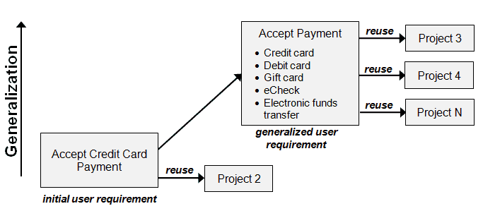
Figure 1: Generalized requirements offer greater reuse potential, Source [5]
An interesting approach to making requirements reusable pioneered by [9] is to use requirements patterns. Essentially it is a systematic approach to specifying a particular type of requirement. A pattern describes a template with classifications for each of the common types of requirements a project might encounter. A template would be populated by a requirements manager and its outcome would be a more detailed requirement specification than if it was written in natural language. The reuse value is found in the structure and content of the requirements written.
Repository
If requirements can’t be found, they can’t be reused. For effective reuse, having a searchable repository to store requirements information is useful. The repository can take several forms such as a network folder with previous project requirements documents; requirement sets stored in a requirements management tool that can be searched across projects; a database that stores requirement sets that can searched; and others.
With a repository, it is important to consider that there is a suitable strategy and process in place for efficient discovery, retrieval, and reuse.
If requirements management tools are used, questions need to be asked about how requirements can be reused. Writing requirements in accordance with standard patterns can provide fields to search, or a set of attributes within the requirement management tool can assist with searching.
Organizational Culture
Reuse should be encouraged by management. Implementing a reuse strategy may need time and effort, but it is likely to make teams more productive and effective. Reused requirements may not be perfect, but even if the project saves a fraction of the time that might have otherwise been spent on the analysis and elicitation, then it’s an efficiency gain.
A culture that encourages requirements managers to borrow first and create second can improve the productivity of the both requirement managers and teams to lead to better efficiency in projects.
Summary and Conclusions
Reuse has several benefits such as project cost savings, increase in productivity, and the quality of requirements. However, there are risks associated with implementing reuse. These risks need to be considered when reusing requirements from different projects. When deciding whether a project’s requirements are reused, the project’s size, complexity, and risks need consideration.
In the rail industry, there are a range of mechanisms in common use, for learning lessons and for knowledge elicitation from previous projects. Requirements reuse within the requirement management discipline is an area that offers the prospect to improve current practice and realize benefits in cost and quality. Software applications provide several areas to consider when examining requirement reuse, including the extent of reuse, modification, and how reuse is performed.
In rail projects, there exist opportunities for reuse with smaller projects that are repetitive in nature such as track renewals and other replacement projects. Large projects also have elements that can be reused, but the necessary analysis needs to be undertaken to determine applicability.
Implementing requirements reuse is a change in mindset. Proactive reusable requirements writing needs to take place to ensure requirements are of high quality, and where applicable, generalization needs to be sought for reuse value. How an organization stores and structures information, and its attitudes toward reuse are also important factors in implementing good reuse in requirement management.
INCOSE is an organization founded to develop and disseminate the interdisciplinary principles and practices that enable the realization of successful systems. It has a mission to share, promote, and advance the best systems engineering practices from across the globe for the benefit of humanity and the planet. It has a number working groups that are actively working to improve system engineering practice, including the Requirements Management Working Group. [10]
List of Acronyms Used in this Paper
Acronym Explanation
IEEE Institute of Electrical and Electronics Engineers
INOCSE International Council on Systems Engineering
ISO/IEC/IEEE 15288, “Systems and Software Engineering – System Life Cycle Processes,” Geneva, 2015
C. Palomares, X. Franch and C. Quer, “Requirements Reuse and Patterns: A Survey,” Empirical Software Engineering,
vol. 22, pp. 1-44, 2016.
Toval, B. M. Valle, J. Nicolás and J. Lasheras, “Eight key issues for an effective reuse-based requirements process.” Computer Systems Science and Engineering, vol. 23, pp. 373-385, 2008.
D. Fucci, A. Falkner, G. Schenner, F. Brasca, T. Männistö, A. Felfernig, W. Maalej, C. Palomares, X. Franch, D. Costal, M. Raatikainen, M. Stettinger, Z. Kurtanović, T. Kojo and L. Koenig, “Needs and challenges for a platform to support large-scale requirements engineering: a multiple-case study,” in The 12th ACM/IEEE International Symposium, 2018.
K. Wiegers and J. Beatty, Software Requirements, 3 ed., Microsoft Press, 2013.
Y. Chernak, “Requirements Reuse: The State of the Practice,” in IEEE International Conference on Software Science, Technology and Engineering, Herzlia, 2012.
INCOSE, Systems Engineering Handbook, 4 ed., Wiley, 2015.
INCOSE, “Guide for Writing Requirements,” San Diego, 2019.
S. Withall, Software Requirement Patterns, Redmond: Microsoft Press, 2007.
INCOSE, “INCOSE UK Working Groups,” [Online]. See https://incoseuk.org/Groups/Working%20Groups [Accessed 01 02 2020]
About the Author
 Aurangzeb Awal is a Senior Systems Engineer in Transport for London Engineering. He is a chartered engineer who has over 9 years’ experience in the systems engineering practice, working within multi-disciplined teams across Defense and Rail industries and has been involved across the systems life-cycle. His system engineering expertise includes: requirements elicitation and management; system architecture development; integrated testing and evaluation strategies; configuration management and change control; and verification and validation processes. He holds a master’s degree in aerospace engineering from Queen Mary, University of London.
-
- INCOSE Americas Sector Activities
by
Tony Williams, ESEP
Director – INCOSE Americas Sector
The INCOSE Americas Sector includes 43 Chapters with over 5,000 INCOSE members in North and South America. Given this huge footprint, there is a huge volume and range of activities. This update focuses on three areas.
First, even though most Sector I chapters are far more ‘local’ than the national chapters found elsewhere in the world, each chapter still serves a significant geographic region, and as a result, it is usually impossible for all Chapter members to travel to a local chapter meeting, either because of the distance involved or simply the factor of modern traffic. As a result, more and more chapters are leveraging technology and web-casting for their meetings. By employing these tools, the Chapters have created value for our members, not only at the local level, but since these web-cast meetings can be accessed globally and are often recorded for future use, these Chapter technical programs and tutorials are morphing into unique INCOSE intellectual capital. As this trend continues, we will better advertise the programs and also provide an indexed and searchable library of recorded programs – an incrementally growing database of current technical topics! (View the text box to get a glimpse into the Washington Metro Area tutorial programs.)
Washington Metro Area Chapter 2019 Tutorial Programs
May 11, 2019
Service in Design: Where Human Centered Design Meets Complex SoS Engineering
Dr. Edith Hughes
June 15, 2019
Systems Thinking Tutorial
Barclay Brown
June 29, 2019
Tutorial on INCOSE SE Handbook and CSEP
Dr. Shakila Kahn and Dr. Muhammad Islam
September 28, 2019
Organization Agility Simulation Part 1
Dr. Shelley Kirkpatrick
November 16, 2019
Organization Agility Simulation Part 2
Dr. Shelley Kirkpatrick and Sarah Miller
Secondly, in addition to these frequent, typically monthly, Chapter technical programs, Sector I chapters have planned and conducted regional events, including conferences and workshops, that engage our members and provide huge learning opportunities. In 2019 alone, these events included, among others:
- Socorro Systems Summit (April, Socorro, New Mexico USA)
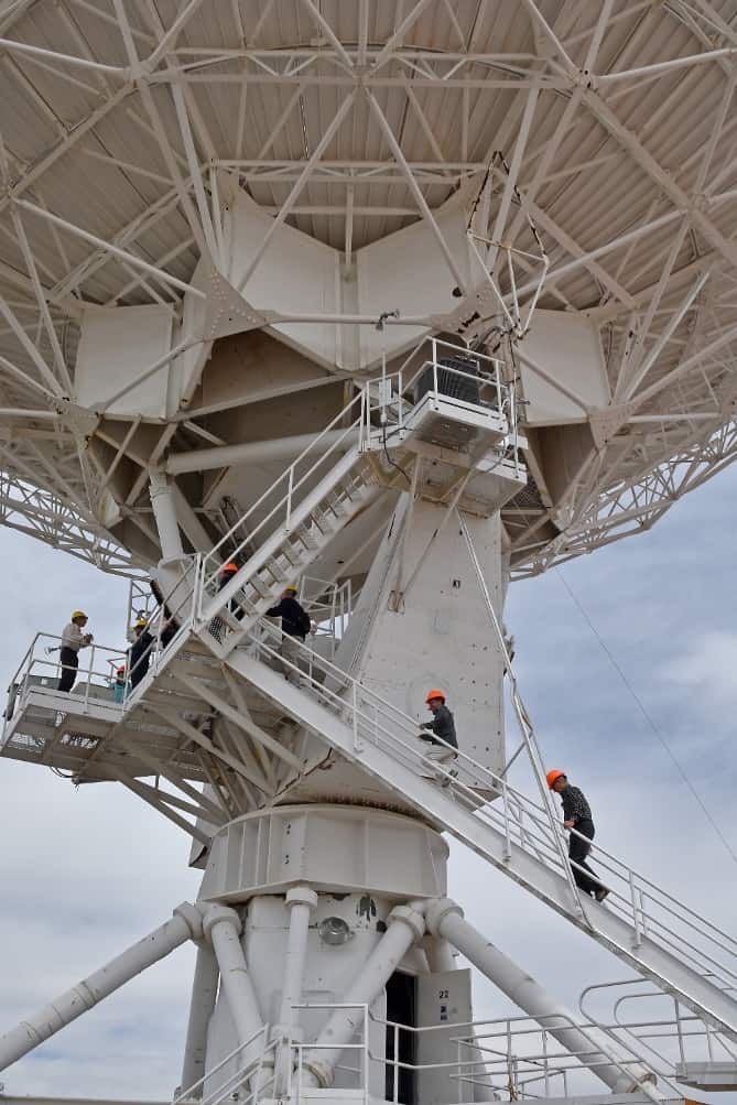
Attendees from the Socorro Systems Summit touring the Large Antenna Array, National Radio Astronomy Observatory
- 5th Annual Systems Engineering in Healthcare Conference (May, Minneapolis, Minnesota USA)
- 2nd Annual Western States Regional Conference (September, Los Angeles, California USA)
- 3rd Annual Texas Gulf Coast Chapter/O&G Working group Conference (October, Houston, Texas USA)
- 13th Annual Great Lakes Regional Conference (October, Cleveland, Ohio USA)
- 1st Annual INCOSE New England Fall Workshop – “SE for Safety Critical Cyber Physical Systems”, (October, Storris, Connecticut USA)
- 2019 INCOSE San Diego, California USA Mini-Conference (November)
Chesapeake Chapter Members ‘representing’ at the INCOSE IW 2020
Dr. George Bollas from UConn speaking at the opening of the New England Fall Workshop
Dorothy Beneviste pours ‘radioactive’ popcorn at the Western States Regional Conference in Los Angeles
The final area is the Chapter activities presented at the INCOSE International Workshop in Torrance, California USA in January 2020. The IW provides a forum that is used by INCOSE’s working groups to get-together for some key working sessions as well as creating and reviewing products. For this year’s IW, the Sectors added a set of Chapter topics, focused on the needs and challenges facing chapter leaders. This year’s sessions included:
- Creating strategic and operating plans (also known as “How to ace the circle awards”).
- Planning and executing a great chapter meeting.
- Best practices for planning and executing a web meeting.
- A tutorial for creating and maintaining a Chapter Web site.
- New Chapter Leader training, featuring INCOSE Board members and leadership and covering the full scope of INCOSE activities.
Looking forward into 2020, I foresee building on all three of these areas, taking our Chapters to the next level, and continually improving our member’s INCOSE experiences.
4. Systems Engineering News
4.1 Johns Hopkins Whiting School of Engineering’s Mapping Tool Tracks Coronavirus Outbreak in Real Time
The Johns Hopkins Center for Systems Science and Engineering has built and is regularly updating an online dashboard for tracking the worldwide spread of the coronavirus outbreak that began in the Chinese city of Wuhan.
Lauren Gardner, an associate professor of civil and systems engineering and CSSE’s co-director, spearheaded the effort to launch the mapping website on Wednesday. The site displays statistics about deaths and confirmed cases of coronavirus, or 2019-nCoV, across a worldwide map. It also allows visitors to download the data for free.
“We built this dashboard because we think it is important for the public to have an understanding of the outbreak situation as it unfolds with transparent data sources,” Gardner said. “For the research community, this data will become more valuable as we continue to collect it over time.”
4.2 The Coronavirus: What You Can Do to Help in Simple Terms
From the Folding@Home website:
We’re simulating the dynamics of COVID-19 proteins to hunt for new therapeutic opportunities.
Proteins are molecular machines that perform many functions we associate with life. They sense the environment (e.g. in taste and smell), perform work (e.g. muscle contraction and breaking down food), and play structural roles (e.g. your hair). They are made of a linear chain of chemicals called amino acids that, in many cases, spontaneously “fold” into compact, functional structures. Much like any other machine, it’s how a protein’s components are arranged and move that determine the protein’s function. In this case, the components are atoms.
Viruses also have proteins that they use to suppress our immune systems and reproduce themselves.
To help tackle coronavirus, we want to understand how these viral proteins work and how we can design therapeutics to stop them.
There are many experimental methods for determining protein structures. While extremely powerful, they only reveal a single snapshot of a protein’s usual shape. But proteins have lots of moving parts, so we really want to see the protein in action. The structures we can’t see experimentally may be the key to discovering a new therapeutic.
Using football as an analogy for the experimental situation, it’s as if you could only see the players lined up for the snap (the single arrangement the players spend the most time in) and were blind to the rest of the game.
 Seeing a single structure of a protein (left) is like seeing players lined up for the snap in football. Important information, but a lot missing too. The protein structure shows a sphere for each atom (blue) and red arrows highlighting the one drug binding site in this protein.
Our (Folding@Home’s) specialty is in using computer simulations to understand proteins’ moving parts. Watching how the atoms in a protein move relative to one another is important because it captures valuable information that is inaccessible by any other means.
Taking the experimental structures as starting points, we can simulate how all the atoms in the protein move, effectively filling in the rest of the game that experiments miss.
Follow this link to watch a short movie capturing how the protein shown before moves is like getting to watch the whole football game. In this case, we see a pocket form that was absent in the experimental structure.
Doing so can reveal new therapeutic opportunities. For example, in our recent paper, we simulated a protein from Ebola virus that is typically considered ‘undruggable’ because the snapshots from experiments don’t have obvious druggable sites. But, our simulations uncovered an alternative structure that does have a druggable site. Importantly, we then performed experiments that confirmed our computational prediction, and are now searching for drugs that bind this newly discovered binding site.
 An experimental structure of an Ebola protein doesn’t have obvious druggable sites (no deep pockets among the atoms shown as spheres).
Our simulations captured a motion that creates a potentially druggable site in this Ebola protein. Instead of showing spheres for each atom, this cartoon shows a ribbon tracing the linear chain of amino acids (chemicals) the protein is made of.
We want to do the same thing with coronavirus, and you can help! In fact, there are a number of ways you can help, and they’re not mutually exclusive.
Downloading Folding@home and helping us run simulations is the primary way to contribute. These calculations are enormous and every little bit helps! Each simulation you run is like buying a lottery ticket. The more tickets we buy, the better our chances of hitting the jackpot. Usually, your computer will never be idle, but we’ve had such an enthusiastic response to our COVID-19 work that you will see some intermittent downtime as we sprint to setup more simulations.
Please be patient with us! There is a lot of valuable science to be done, and we’re getting it running as quickly as we can.
If you don’t have computers to contribute or are feeling particularly generous, you can also make donations through Washington University in St. Louis. These funds are used for a number of purposes, including: 1) supporting our software engineering and server-side hardware (particularly important right now as we scale up rapidly!) and 2) buying compounds to test experimentally based on insight from our simulations.
Of course, please take precautions to help prevent the spread of the virus by washing your hands, social distancing, etc. doing so helps sustain the medical system and buys scientists time to hunt for therapies.
4.3 Message from INCOSE President Regarding COVID-19
Dear INCOSE Members,
It has been three weeks since the last time I sent a message to our INCOSE family regarding COVID-19. Since then it has become a pandemic with many countries, organizations, and businesses introducing new restrictions and guidance to minimize the rapid spread of the virus. The fact is the COVID-19 will be with us for quite some time and all measures taken to date will “flatten the curve of infected numbers” but potentially extend the duration of COVID-19. We therefore need to take care of our families and friends and remain positive under these trying times.
Firstly, from the INCOSE leaders, our hearts and thoughts are with you all. We would also like to send a big thank you to all our members and their families who are able to continue to offer services to their communities, whether they are “front-line responders”, the engineer on a critical project, the local transport provider or the retailer. Your contributions are outstanding.
To all members of INCOSE we encourage you to follow the guidance provided by your authorized authorities and the World Health Organization (WHO). As such the following restrictions now apply–
- INCOSE is prohibiting all INCOSE related meetings and external INCOSE representation requiring air travel, whether domestic or international, without approval from the INCOSE Officers until 31 May 2020, at which time this restriction will be reviewed.
- INCOSE highly discourages any INCOSE related face-to-face meeting and the decision to hold such a meeting is at the sole discretion of the INCOSE meeting organizer.
o We encourage you to consider alternative means of communication available such as conference calling.
o Social distancing and good hygiene practices are to be employed where practical.
- Any external INCOSE representation in support of another organization’s face-to-face meeting is at the individual member’s discretion.
In parallel to the above restrictions, we have been working hard behind the scenes to support all our INCOSE activities and members.
We have a task team evaluating different remote participation applications to be made available for all members for all INCOSE related meetings, worldwide. It is likely we may have more than one recommended application with guidance on which application is best suited for a specific virtual participation, location and volume of users.
We are assisting various groups within INCOSE to restructure their programs, events and meetings to make greater use of remote participation and, where possible and practical, to reschedule events later in the year. If you need assistance, please reach out to helpdesk@incose.org.
We are keeping a close eye on the changing circumstances in Cape Town and globally with respect to the International Symposium IS 2020, July 2020. At present, the South African government has placed restrictions on travel and gatherings until further notice, which can prevent us holding IS 2020 in Cape Town. However, from further discussions these restrictions may or may not continue past May. It is unknown at this point in time. As such we are continuing to plan the event taking into consideration –
- The possibility of virtual participation for some sessions,
- A smaller scale conference with greater outreach post conference date,
- Additional hygiene services at the event,
- The possibility of delaying the event,
- Exploring options to publish finalized papers in various online proceedings.
The well-being of our members is our highest priority. We will continue to closely follow the recommended health and safety precautions. Likewise, we will keep you informed on a regular basis of any updates relating to COVID-19.
Keep well, keep safe.
Kerry Lunney
INCOSE President
4.4 IEEE Adopts New Diversity Statement

Illustration: Shutterstock
At the Institute of Electrical and Electronics Engineers (IEEE), diversity is an important and valued strength. IEEE is committed to maintaining an environment in which all are welcome to collaborate, to contribute to the community, to support the growth of the engineering profession and professional colleagues and to advance technology for the benefit of humanity.
To that end, in February 2019, the IEEE Board of Directors formed an ad hoc committee to review the organization’s focus on diversity, inclusion, and professional ethics. The ad hoc committee’s work included efforts aimed at the continued improvement of awareness and understanding of IEEE’s commitment to diversity, inclusion and professional ethics, and efforts focused on improving the processes by which IEEE members hold each other accountable for our commitments.
One of the recommendations from this committee was a proposal to include a diversity statement as part of the IEEE policies. The IEEE Board of Directors considered the proposal and during its November meeting approved the following statement for incorporation into the IEEE policies:
IEEE’s mission to foster technological innovation and excellence to benefit humanity requires the talents and perspectives of people with different personal, cultural, and disciplinary backgrounds. IEEE is committed to advancing diversity in the technical profession, and to promoting an inclusive and equitable culture in its activities and programs that welcomes, engages and rewards those who contribute to the field without regard to race, religion, gender, disability, age, national origin, sexual orientation, gender identity, or gender expression.
This change to the IEEE policy reflects IEEE’s longstanding commitment to ensure the engineering profession maximizes its impact and success by welcoming, engaging, and rewarding those who contribute to the field in an equitable manner.
4.5 Mapping Potholes by Phone (the West Bank’s Roads Were Smoother)
A group of engineering students, from schools like M.I.T., Harvard and Birzeit University in the West Bank, have developed an app that turns a smartphone into a tool to track potholes and measure overall road quality. This project could improve life in many ways for drivers — and everyone else. Test users have already come up with some surprising data as a result of using the app – read more about the results of testing here.
4.6 Using Panarchy to Change a Complex System
Panarchy is a conceptual framework to account for the dual, and seemingly contradictory, characteristics of all complex systems – stability and change.
How do you change a complex system? This is the quintessential question facing the people eager to change systems — like politicians, Scrum Masters, thought leaders, and other change agents. The Liberating Structure ‘Panarchy’ offers a powerful perspective and allows you to put systems thinking into practice. “Even though it is perhaps the most complicated of them all, Panarchy brings together all the promises of Liberating Structures: engage everyone and unleash change on every level. Drawing from a wide variety of disciplines, from psychology to biology and from history to engineering, it has made us aware of how resistant complex systems are against change.
For example, even if you somehow manage to change from one day to the next how work is done in an organization (‘work faster!’), implicit norms learned in the past may run counter to that (‘here, we take it slow so everyone can keep up’). But then what? “Thankfully, Systems Thinking also offers us a perspective on how we can systems: find leverage points. One of the characteristics of a complex system is that even a small push in the right area can start shifting the entire system. Consider how spreading ‘fake news’ through social networks is currently reshaping our view on the world, and how that is in turn affecting politics and our society at large. Or a more positive example is how a small tax benefit in European countries resulted in a huge growth in the number of installed solar panels. So, finding “leverage points” is one way to change systems, and that is what ‘Panarchy’ is all about.
The Liberating Structure ‘Panarchy’ exists to help groups explore and analyze entire systems, their parts, layers, and subsystems and how they interact. Not only does ‘Panarchy’ help groups build at least some understanding of how their system works, but it also helps find leverage points. And rather than doing this alone or with a small group, the complexity is exactly why you want to include as many perspectives and pairs of eyes as possible.
The concept of Ecocycle Planning
Panarchy strongly relies on the concept of the Ecocycle, and a related structure called Ecocycle Planning. The key point is that ideas and activities move through a continuous cycle from conception to birth, birth to maturity and maturity to creative destruction and re-invention. Healthy systems have things going on all over the Ecocycle, which indicates that there is innovation (gestation & birth), stability (maturity) and a clear sense of what has stopped being useful (creative destruction). But more often than not, activities get stuck in a poverty trap (‘Good idea, but no time’) or the rigidity trap (‘No time to figure out how to do this in a better way’). In Panarchy, the analysis shifts from one level to many different levels. This is just one example — you can add many more or add entirely different levels (e.g. culture, products). In Panarchy, what is going on each level in the complex systems is projected onto an Ecocycle. This shows not only what is happening in each level, but also how the levels are connected. For example, Panarchy may reveal that developers keep getting stuck in technical issues because they have no experienced peers to help out on the level of the team. In turn, this may be caused by a focus on hiring cheap but inexperienced developers on the organizational level.
This structure was created by Henri Lipmanowicz and Keith McCandless, inspired by work by Brenda Zimmerman and David Hurst. The concept of Panarchy is based on earlier work by the ecologist C.S. Hollins.
4.7 MITRE (USA) Unveils Laboratory Focused on Autonomous Technology
Assistive technologies in autonomous vehicles are evolving quickly and occupying more important roles in the way we work, travel, and manage our homes. MITRE created the Mobile Autonomous Systems Experimentation (MASE) Laboratory to research ways to accelerate advanced autonomous technology and provide objective perspective and recommendations for broad impact in multiple domains, including drones, commercial aircraft, tanks, and self-driving vehicles.
The lab’s centerpiece is the MASE Jeep—a commercially available Grand Cherokee augmented for autonomy by an aftermarket vendor and outfitted by MITRE engineers with sensors, analytic and data recorders, and powerful processors. The Jeep provides the opportunity to explore new autonomous technologies and cutting-edge algorithms on a large mobile platform. The lab provides an integrated testing environment for emerging hardware, software, and approaches that will help to inform government sponsors and collaboration partners.
“We have human interaction researchers who are experts at cognitive loading and how to effectively communicate between computers and people,” says Zachary LaCelle, a senior autonomous system engineer at MITRE. “We have cyber experts and autonomy experts working on ground transportation, urban air mobility, and defense applications. Our systems thinking mentality accelerates solutions to all of these problems. This broad combination of domain expertise allows us to provide additional, unique perspectives in this cutting-edge challenge area.”
Read more about MITRE in Featured Organizations 5.1
4.8 How Can We Combat Climate Change?
Leuven (capital and largest city of the province of Flemish Brabant in the Flemish Region of Belgium) is one of 15 cities across Europe taking part in EIT Climate-KIC’s (Europe’s leading climate change initiative): Deep Demonstration of Healthy, Clean Cities—the first cohort in an initiative planned to grow exponentially.
At the heart of the Deep Demonstration methodology is a readiness and intent to work differently, embrace transformational outcomes, and adopt a systemic approach. Notably, all participating cities operate inter-departmental municipal teams and have robust systems to involve stakeholders in every step of the way.
4.9 Order of the Engineer Celebrates 50th Anniversary
The Order of the Engineer was initiated in the United States to foster a spirit of pride and responsibility in the engineering profession, to bridge the gap between training and experience, and to present to the public a visible symbol identifying the engineer. On Thursday, April 2, 2020. the Order will hold a celebratory dinner at Cleveland State University, the home of the founding Link.
From the website:
The Order is not a membership organization; there are never any meetings to attend or dues to pay. Instead, the Order fosters a unity of purpose and the honoring of one’s pledge lifelong.have
4.10 Standards Development: ISO24641 Methods and Tools for Model-Based Systems
ISO/IEC CD 24641 [ISO/IEC NP 24641] – Systems and Software Engineering – Methods and Tools for Model-based Systems and Software Engineering is under development through the technical committee: ISO/IEC JTC 1/SC 7 Software and systems engineering as announced on December 7, 2019.
About ISO/IEC JTC 1/SC 7
SC7 delivers standards in the area of software and systems engineering that meet market and professional requirements. These standards convers the processes, supporting tools and supporting technologies for the engineering of software products and systems. Systems engineering, whose origin is traceable to industrial engineering, is defined as an interdisciplinary approach governing the total technical and managerial effort required to transform a set of customer needs, expectations, and constraints into a solution and to support that solution throughout its life. SC7, whose scope is Software and Systems Engineering, can thus be described as a horizontal committee who produce generic standards that are technology agnostics and independent of the application domain. These standards are principally focused on process models and good practices (Methods and techniques).
5. Featured Organizations
5.1 MITRE

“A development program for active INCOSE members seeking to improve their leadership skills in an open, collaborative environment.”
The MITRE Corporation is an American not-for-profit organization based in Bedford, Massachusetts and McLean, Virginia. MITRE operates several Federally Funded Research and Development Centers (FFRDCs), special organizations that promote objective collaboration to solve large-scale problems:
- Special Access for Cities and States
- National Security Engineering Center
- Center for Advanced Aviation System Development
- Center for Enterprise Modernization
- Homeland Security Systems Engineering and Development Institute
- Judiciary Engineering and Modernization Center
- Centers for Medicare & Medicaid Services (CMS) Alliance to Modernize Healthcare
- National Cybersecurity FFRDC
MITRE has published a Systems Engineering Guide to convey its SE knowledge on a wide variety of topics.
5.2 American Society of Agricultural and Biological Engineers
The American Society of Agricultural and Biological Engineers is an educational and scientific organization dedicated to the advancement of engineering applicable to agricultural, food, and biological systems. Founded in 1907 and headquartered in St. Joseph, Michigan, ASABE comprises members in more than 100 countries.
Agricultural, food, and biological engineers develop efficient and environmentally sensitive methods of producing food, fiber, timber, and renewable energy sources for an ever-increasing world population.
ASABE membership is open to all—engineers as well as non-engineers—who are interested in engineering and technology for agricultural, food, and biological systems.
5.3 Caspian Engineers Society

The Caspian Engineers Society (CES) is non-profit organization, founded on the principle of developing “Engineering Culture” across the Caspian region in Turkey. The mission of The CES is to develop engineers professionally, support regional industry by introducing world class experience and technology, and offer an engineering network. Further aim is to promote engineering awareness among the public that will drive “Be Engineer” movement and spark the interest of young generation in engineering.
Follow the Caspian Engineering Society on LinkedIn and Facebook/
6. News on Software ToolS Supporting
Systems Engineering
-
- The REUSE Company Maps out INCOSE 2019 Rules with SE Suites Metrics
The REUSE Company has a Systems Engineering Suite that allows an accurate assessment of requirements quality in correlation with the new INCOSE 2019 rules. REUSE has mapped 2019 INCOSE metrics with the REUSE tool metrics in a mapping table. This mapping is free to download on in the REUSE resources library through the following link.
-
- New Web Interface for Requirements Management
ALM Solution
- New Web Interface for Requirements Management
Visure Solutions, Inc. has launched Visure Web Reviewer 5.0, an intuitive web interface. This introduction will allow users to review and approve requirements, test and design specifications through the web. The new web-based version will allow stakeholder (technical and non-technical users) of RM – including marketing teams, management teams, customers and suppliers – to easily navigate the complex ALM process. Visure Reviewer web-based interface will also help increase efficiency and optimize processes while speeding the product development process by saving time, strengthening alignment, and ensuring quality and compliance.
6.3 Leverage Standardized Encryption and Licensing for Modelica Libraries
SEMLA (Standardized Encryption of Modelica Libraries and Artifacts) is a system for distributing proprietary Modelica libraries which supports:
- Encryption
- Licensing
- Secure decryption of encrypted Modelica libraries
- Platform independence
Libraries are bundled in the MLC (Modelica Library Container) format, which are zip files containing the encrypted libraries and a manifest.
SEMLA was designed by Modelon developers to be an open source encryption standard, which allows library vendors to protect the intellectual property contained within their Modelica libraries. SEMLA can also prevent libraries from being copied and re-used by other Modelica users unless authorized by the library vendor.
SEMLA Interface
The SEMLA protocol allows a library vendor to access licensed and encrypted Modelica libraries via an LVE (Library Vendor Executable) interface, using a secure communication channel. The LVE is controlled by the library vendor and allows the vendor to choose which licensing and encryption schemes, if any, will be implemented in the protocol.
Learn More about the SEMLA Protocol
7. Systems Engineering Publications
7.1 Diversity in Systems Engineering INSIGHT Available
|
A special issue of INSIGHT focusing on Diversity in Systems Engineering is available for free download throughout March 2020. Check it out here. |
|
7.2 Illuminating the world – the Choice of the Era to Rise above the Atmosphere |
by
Huifeng Xue

Illuminating the world – the Choice of the Era to Rise above the Atmosphere is a comprehensive academic work that focuses on the theories and philosophies in the field of systems engineering. It consists of three parts with 10 chapters in total, describes the necessity of systems engineering in solving current world problems, expounds on the history and evolution of systems engineering as an interdisciplinary field, analyses both reductionist and holistic approaches as its methodologies, and provides a unique astronautics point of view.
In the book, author Huifeng Xue made his research and explorations as an attempt to extend and advance the Chinese school of systems engineering, which was first introduced and developed by Hsue-Shen Tsien, renowned Chinese mathematician, cyberneticist, aerospace engineer, and physicist. In 1954, Tsien’s book Engineering Cybernetics was published, laying the theoretical foundation for the thought and theory of system engineering in China. He later published his paper Organizational Management Technology — Systems Engineering on Sept. 27, 1978, which was considered as the birth of the Chinese school of systems engineering. The book also accentuates the application of systems engineering in human exploration of outer space in the new era. As an achievement that blends human wisdom from the West and the East, the theoretical system and practical knowledge of systems engineering will not only push forward our exploration of existing knowledge-based system, our scientific study of the human biological system, and our development of our social system, but also provide a philosophical foundation and guidance for our walk towards the five-dimensional space, the establishment of a interplanetary society, and the continuation and progress of our great wisdom and civilization.
“I hope this book will act as an authoritative source, to provide our readers a comprehensive introduction to the thought and theory of systems engineering, and help reach consensus in building a community with a shared future for mankind,” said Xue, who is also an academician of the International Academy of Astronautics and professor of China’s Northwestern Polytechnic University.
The book will be available at Amazon.com and other online and physical bookstores soon.
Publisher: Prunus Press
Media Contact: XiaoXia Li
Phone: +86 183.0122.0728
Email: 1074589810@qq.com
7.3 An Elegant Puzzle: Systems of Engineering Management
by
Will Larson

From the Amazon.com Website:
There’s a saying that people don’t leave companies, they leave managers. Management is a key part of any organization, yet the discipline is often self-taught and unstructured. Getting to the good solutions of complex management challenges can make the difference between fulfillment and frustration for teams, and, ultimately, the success or failure of companies.
Will Larson’s An Elegant Puzzle orients around the particular challenges of engineering management–from sizing teams to technical debt to succession planning–and provides a path to the good solutions. Drawing from his experience at Digg, Uber, and Stripe, Will Larson has developed a thoughtful approach to engineering management that leaders of all levels at companies of all sizes can apply. An Elegant Puzzle balances structured principles and human-centric thinking to help any leader create more effective and rewarding organizations for engineers to thrive in.
7.4 Personal Information Security & Systems Architecture: Techniques for Personally Identifiable Information Management in a Business
by
Keith Marlow
From the Amazon.com Website:
From the software engineer to product manager, CTO, and CEO and the Board, all have a role in implementing appropriate personal information security. Securing such personal information on computers is where this book comes into its own. Globally, personal data breaches are at record levels. In 2017 identity theft, and related fraud cost $16 billion, affecting 6.7 million people, up 8% from 2016 (Javelin Strategy & Research, 2018). Generic cyber-attacks in APAC alone has cost an estimated $1.7 trillion in 2017 (Yu, 2018). The amount stolen is staggering; it’s a multi-billion dollar “underground business” affecting everyone. Governments, given such breaches and rampant wholesale data collection, are quickly creating robust legislation. Businesses, when faced with having to meet such evolving regulatory requirements, find it hard working out what to do; this is where this book excels. It explains what to focus on, when and why. Detailed are security, architectural and technical best practices based on real-world experience, combined with a PII focus – giving confidence that sensitive information is handled correctly. With this book, you will learn how to discover, classify and value personal information in your business systems. Then it will guide you in determining what security controls are appropriate to secure the personal information and what technology you need to be well placed to follow data processing regulations.
Formats: Kindle, paperback
Publisher: Aykira Pty Ltd (September 14, 2018)
ISBN-10: 0648350118
ISBN-13: 978-0648350118
7.5 Visual Models for Software Requirements – Developer Best Practices
by
Anthony Chen and Joy Beatty
From the Amazon.com Webpage:
Apply best practices for capturing, analyzing, and implementing software requirements through visual models—and deliver better results for your business. The authors—experts in eliciting and visualizing requirements—walk you through a simple but comprehensive language of visual models that has been used on hundreds of real-world, large-scale projects. Build your fluency with core concepts—and gain essential, scenario-based context and implementation advice—as you progress through each chapter.
- Transcend the limitations of text-based requirements data using visual models that more rigorously identify, capture, and validate requirements
- Get real-world guidance on best ways to use visual models—how and when, and ways to combine them for best project outcomes
- Practice the book’s concepts as you work through chapters
- Change your focus from writing a good requirement to ensuring a complete system
Formats: Kindle, paperback
Publisher: Microsoft Press (July 25, 2012)
ISBN-10: 0735667721
ISBN-13: 978-0735667723
7.6 Software Requirements – Developer Best Practices (3rd Ed)
by
Karl Wiegers and Joy Beatty
From the Amazon.com Website:
Now in its third edition, this classic guide to software requirements engineering has been fully updated with new topics, examples, and guidance. Two leaders in the requirements community have teamed up to deliver a contemporary set of practices covering the full range of requirements development and management activities on software projects.
- Describes practical, effective, field-tested techniques for managing the requirements engineering process from end to end.
- Provides examples demonstrating how requirements “good practices” can lead to fewer change requests, higher customer satisfaction, and lower development costs.
- Fully updated with contemporary examples and many new practices and techniques.
- Describes how to apply effective requirements practices to agile projects and numerous other special project situations.
- Targeted to business analysts, developers, project managers, and other software project stakeholders who have a general understanding of the software development process.
- Shares the insights gleaned from the authors’ extensive experience delivering hundreds of software-requirements training courses, presentations, and webinars.
New chapters are included on specifying data requirements, writing high-quality functional requirements, and requirements reuse. Considerable depth has been added on business requirements, elicitation techniques, and nonfunctional requirements. In addition, new chapters recommend effective requirements practices for various special project situations, including enhancement and replacement, packaged solutions, outsourced, business process automation, analytics and reporting, and embedded and other real-time systems projects.
Formats: Kindle, paperback
Publisher: Microsoft Press (3rd edition) August 25, 2013
ISBN-10: 0735679665
ISBN-13: 978-0735679665
7.7 DevOps: A Software Architect’s Perspective
by
Len Bass, Ingo Weber, and Liming Zhu
From the Amazon.com Webpage:
DevOps promises to accelerate the release of new software features and improve monitoring of systems in production, but its crucial implications for software architects and architecture are often ignored.
In DevOps: A Software Architect’s Perspective, three leading architects address these issues head-on. The authors review decisions software architects must make in order to achieve DevOps’ goals and clarify how other DevOps participants are likely to impact the architect’s work. They also provide the organizational, technical, and operational context needed to deploy DevOps more efficiently, and review DevOps’ impact on each development phase. The authors address cross-cutting concerns that link multiple functions, offering practical insights into compliance, performance, reliability, repeatability, and security.
This guide demonstrates the authors’ ideas in action with three real-world case studies: datacenter replication for business continuity, management of a continuous deployment pipeline, and migration to a micro-service architecture.
Comprehensive coverage includes:
- Why DevOps can require major changes in both system architecture and IT roles.
- How virtualization and the cloud can enable DevOps practices.
- Integrating operations and its service lifecycle into DevOps.
- Designing new systems to work well with DevOps practices.
- Integrating DevOps with agile methods and TDD.
- Handling failure detection, upgrade planning, and other key issues.
- Managing consistency issues arising from DevOps’ independent deployment models.
- Integrating security controls, roles, and audits into DevOps.
- Preparing a business plan for DevOps adoption, rollout, and measurement.
Formats: Hardcover, paperback
Publisher: Addison-Wesley Professional (May 28, 2015)
ISBN-10: 9780134049847
ISBN-13: 978-0134049847
8. EDUCATION AND ACADEMIA
8.1 CIMdata and SMS ThinkTank Announce New Systems Modeling & Simulation Certificate Program
CIMdata, Inc., the leading global PLM strategic management consulting and research firm, and SMS ThinkTank, an industry leading resource providing system modeling and simulation expertise, announce that CIMdata has added a new Certificate Program to its PLM Leadership education and training offerings.
The new “Systems Modeling & Simulation Certificate Program,” has been created by combining CIMdata’s knowledge and experience with that of SMS ThinkTank. The new program is an integral part of CIMdata PLM Leadership-the PLM industry’s leading non-biased education and training offering.
The goal of the new program is to provide a superior educational experience for today’s simulation and analysis professionals. It will be delivered through a series of education and training sessions that will equip those involved in systems modeling and/or simulation with a strong understanding of systems modeling and simulation concepts and industry-leading best practices.
The program will be offered in three configurations:
- SMS for Executives – a one-day class designed for those executives seeking an understanding of engineering analysis and virtual modeling.
- SMS for Managers – a five-module program, delivered over two 3-day courses, designed for those using simulation at various lifecycle stages and/or supporting simulations in various functions.
- SMS for Practitioners-a five-module program, delivered over two 3.5-day courses, designed for general users, application engineers, systems engineers, simulation engineers, development engineers, subject matter experts, and IT analysts.
The Systems Modeling & Simulation Certificate Program leverages a common systems engineering and product data model that encompasses simulation, analysis, benefits, requirements, platform, program, project, systems definition, product structure, lifecycle, and configuration management capabilities.
For more information on CIMdata’s Systems Modeling & Simulation Certificate Program visit https://www.cimdata.com/en/education/sms-certificate-program.
8.2 The Roux Institute of Northeastern University
Portland Maine USA
Northeastern’s Roux Institute is designed as an engine of innovation, talent, and economic growth in Portland, the state of Maine, and the region. Through partnership, the Roux Institute aims to create an agile workforce prepared to thrive in a competitive landscape powered by artificial intelligence, and an environment for innovation in the life sciences and other high-growth sectors.
Specialty disciplines include:
- Analytics
- Bioinformatics
- Biotechnology
- Data Science
- Genomics
- Information Systems
- Machine Learning
- Precision Medicine
- Robotics
This new Institute will focus on Research partnerships:
- Access to valuable resources and expertise in experiential AI
- R&D collaboration
8.3 Associate Professor (tenured position) in Modelling, Verification and Quantitative Analysis of Cyber Physical Systems
(CPS)
Paris, France
Application deadline: March, 26th, 2020
Qualifications
- PhD degree in Computer Science
- Strong expertise in at least one of the following fields:
- formal verification (model-checking, proof assistants),
- quantitative analysis for cyber physical systems (energy consumption, safety, security, timing performance, …)
- model driven engineering using multi-paradigm modelling.
- Convincing research record
- Proficient level of written and oral English. If the candidate is not French speaking, she or he must commit to acquire a sufficient level to teach in French as quickly as possible (less than two years)
- Experience in under-graduate and graduate level teaching is preferred
Summary of the Opportunity
The research team of Autonomous and Critical Embedded Systems of Telecom Paris is looking for a tenured Associate Professor (Maître de Conference, permanent position) in the area of Modeling, Verification and Analysis of Cyber Physical Systems (CPS). The candidate is expected to strengthen the research force of the school by contributing to ongoing and future projects related to fundamentals and software related modeling, verification and quantitative analysis of CPS. A specific focus will be given to modelling, verification and analysis in (at least) one of the following contexts: safety, security, autonomous systems, multi-paradigm modelling.
To ensure smooth integration into the research program of ACES and Telecom Paris, it is desired for the candidate to share interests in one or more of the following areas: formal verification, quantitative analysis and model driven engineering of non-functional properties, safety, security, autonomic computing, and multi-paradigm modelling.
The candidate is also expected to join the teaching curriculum of the department of Computer Science of Telecom Paris on a variety of subjects in computer science, with a specialization on cyber physical systems (modelling, design, programming, analysis, …), set up new courses and educational tools on emerging disciplines.
Documents to be provided are listed here
9. Some Systems Engineering-Relevant Websites
Websites that an engineering student should visit on a regular basis
A list of 10 websites that an engineering student should visit to stay on top of engineering developments throughout their degree.
Engineering.com – Information and Inspiration for Engineers
This Website provides video tutorials on engineering and its application, explanation of concepts, principles, software tutorials, video shows, and interesting discussions. It lists relevant engineering jobs related to various disciplines and locations. Various video tutorials and tips to help with interviews are provided. Other interesting features include articles on electronics, 3 D printing, software designing, games, puzzles, and downloadable material provided in its resource section and library.
INCOSE UK Working Groups
This Website provides links to Local Groups, Interest Groups, and Working Groups in INCOSE UK. It also provides useful guidelines for setting up a group.
https://incoseuk.org/Groups/Working%20Groups
10. Standards and Guides
10.1 ISO/IEC/IEEE 29148:2018 Systems and software engineering — Life cycle processes — Requirements engineering
This document:
- specifies the required processes implemented in the engineering activities that result in requirements for systems and software products (including services) throughout the life cycle;
- provides guidelines for applying the requirements and requirements-related processes described in ISO/IEC/IEEE 15288 and ISO/IEC/IEEE 12207;
- specifies the required information items produced through the implementation of the requirements processes;
- specifies the required contents of the required information items;
- provides guidelines for the format of the required and related information items.
This document is applicable to:
- those who use or plan to use ISO/IEC/IEEE 15288 and ISO/IEC/IEEE 12207 on projects dealing with man-made systems, software-intensive systems, software and hardware products, and services related to those systems and products, regardless of the project scope, product(s), methodology, size or complexity;
- anyone performing requirements engineering activities to aid in ensuring that their application of the requirements engineering processes conforms to ISO/IEC/IEEE 15288 and/or ISO/IEC/IEEE12207;
- those who use or plan to use ISO/IEC/IEEE 15289 on projects dealing with man-made systems, software-intensive systems, software and hardware products and services related to those systems and products, regardless of the project scope, product(s), methodology, size or complexity;
- anyone performing requirements engineering activities to aid in ensuring that the information items developed during the application of requirements engineering processes conforms to ISO/IEC/IEEE 15289.
10.2 The New International System of Units (SI): Quantum Metrology and Quantum Standards
Metrology is the science of measurement, and the International System of Units (SI) is the standard for those measurements in fields such as science, engineering, and economics.
This book contains a complete review of the revised SI, which came into force on 20 May 2019. While this book is based on a previous book by the same authors, “Quantum Metrology: Foundations of Units and Measurements,” it is reorganized and revised with new SI definitions and the differences between the previous and the present SI. The book explains and illustrates the physics and technology behind the definitions and their impact on measurements, emphasizing the decisive role quantum metrology has played in the revision.
The individual chapters are updated through the inclusion of the latest results and progress. This book addresses advanced students, researchers, scientists, practitioners, and professionals in the field of modern metrology as well as a general readership interested in the foundations of the new SI definition.
11. Some definitions to close on
11.1 DevOps
DevOps (development and operations) is an enterprise software development phrase used to mean a type of agile relationship between development and IT operations. The goal of DevOps is to change and improve the relationship by advocating better communication and collaboration between these two business units.
Source: Webopedia
11.2 Stakeholder
1. One who is involved in or affected by a course of action
Source: Merriam Webster
2. A person with an interest or concern in something, especially a business.
Source: Oxford Dictionary
11.3 Multi-Factor Authentication (MFA)
Multi-factor authentication is an authentication method in which a computer user is granted access only after successfully presenting two or more pieces of evidence (or factors) to an authentication mechanism: knowledge (something the user and only the user knows), possession (something the user and only the user has), and inherence (something the user and only the user is).
Source: Wikipedia
12. Conferences and Meetings
For more information on systems engineering related conferences and meetings, please go to our website.
The featured event for this edition is:
27th International Conference on Systems Engineering
August 25 – 27, 2020 – Las Vegas, NV (USA)
This series of International Conferences is jointly organized on a rotational basis among three institutions:
- University of Nevada, Las Vegas, USA
- Wroclaw University of Technology, Poland
- Coventry University, UK
In 2018, the series of the conferences was joined by University of Technology Sydney, Australia.
History of the conference:
In 1973 a group of young scientists from Wroclaw University of Technology led by Professor Zdzislaw Bubnicki invited scientists from around the world in order to exchange ideas of modern problems of systems science and engineering. The first International Conference “Systems Science” was held in the European city of Wroclaw, Poland (with some sessions organized in nearby town Szklarska Poręba). The event was a success and the organizers decided to continue with the conference every year. First six editions of Systems Science (till 1979) were organized by Wroclaw University of Technology – attracting scientist from the USA, Japan, India and almost all European countries. After six years of existence, the conference was already well known as a forum for presentation of original papers on a good professional level and for discussions integrating different subjects of systems science and engineering and specialists from universities, research centres, and industry. During the conference in 1979, Professor Zdzislaw Bubnicki decided to organize future conferences in Wroclaw every two years, and Professor Glyn James and his colleagues from the Coventry University in England suggested that they join a team from Wroclaw to organize the conferences in alternate years in Coventry. Consequently, the next edition in 1980 took place in Coventry. In 1983, Professor William Wells from the University of Nevada Las Vegas, USA and his colleagues joined the teams from Poland and England, and the next meeting in 1984 was organized in Las Vegas, USA. Then it was decided, that to call conferences in Poland as “Systems Science” and in England and USA as “Systems Engineering”.
Conference proceedings are published in Springer Publishing or IEEE CS Publishing, and are indexed by ISI Web of Science Proceedings, DBLP, SCOPUS, Google Scholar, and SpringerLink.
Important Dates
Papers due: March 21, 2020
Notification of acceptance: April 20, 2020
Paper registration due: May 17, 2020
Camera-ready (final) papers: May 17, 2020
13. PPI and CTI News
13.1 All PPI and CTI training Now Available Live-Online
Zero travel needed! PPI & CTI online live delivery has arrived! Visit our home page here for more information.
The client arranges and provides:
- a shared, large-format, web browser-connected digital screen
- the capability for all delegates to hear the course facilitator
- the capability for the facilitator to hear each delegate
- the capability for delegates to present in-progress and completed workshop graphics (modeling, etc.) to the facilitator and engage one-on-one with the facilitator and one-on-many with each other.
An example of a suitably equipped room for a class of 8 delegates is:
- 1500mm wide wall mounted display
- internet-enabled computer with camera, ideally one per delegate. A shared computer is viable, however
- up-to-date conferencing software (PPI to advise)
- high speed internet access
- good quality speaker system
- centrally located microphone or distributed microphones
- a dedicated phone handset for one-on-one delegate-facilitator two-way communication, for use mainly during workshops.
Once an expression of interest in live online delivery of a PPI/CTI course is received, we work with the client to define suitable technical facilities. The minimum viable online delivery solution requires only a PC with camera per delegate and PPI/CTI-designated conferencing software.
If you’re interested in receiving online systems engineering training, please contact us and we will be happy to provide you with additional information.
13.2 PPI and CTI Courses Get Re-Accredited
Many of the PPI and CTI courses have once again received accreditation by the Engineering Council of South Africa (ECSA) for continuous professional development (CPD) expiring 2021. In addition, many of PPI courses count towards maintenance of the INCOSE Certificated Systems Engineering Professional (CSEP) accreditation. The applicable accreditations for each course can be found in the relevant course overview on the PPI and CTI pages, see, for example, our Systems Engineering Management course accreditations here.
13.3 PPI-USA has a New Home

PPI-USA has changed its Las Vegas location to the attractive Regatta Drive, Mar-A-Lago area. We are on the street side of the right-hand side of the building in the picture. Our address is:
Project Performance International USA Inc,
2620 Regatta Drive, Suite 102,
Las Vegas NV, 89128
United States of America
Our mailing address is unchanged.
14. PPI and CTI Events
In view of uncertainty related to the COVID-19 virus, most public courses are now offered live-online. Some public courses are still scheduled for physical delivery in small regional areas. Such deliveries will take place only if consistent with government guidance, and with meticulous attention to health and safety of participants. Limited on-site physical deliveries may also be possible in some locations under similarly stringent conditions.
For a full public training course schedule, please visit https://www.ppi-int.com/course-schedule/
Online “in-house” training and consulting activity is a great way to make the most out of present circumstances. Please email contact@ppi-int.com to discuss.
15. Upcoming PPI Participation in Professional Conferences
PPI will be participating in the following upcoming events. We support the events that we are sponsoring, and look forward to meeting old friends and making new friends at the events at which we will be exhibiting.
The INCOSE International Symposium 2020
(Exhibiting)
Date: 18 – 23 July, 2020
Location: Cape Town, South Africa
The INCOSE International Workshop 2021
Date: 29 – 31 January, 2021
Location: Seville, Spain
Kind regards from the PPI SyEN team:
Robert Halligan, Editor-in-Chief, email: rhalligan@ppi-int.com
Ralph Young, Editor, email: ryoung@ppi-int.com
René King, Managing Editor, email: rking@ppi-int.com
Project Performance International
2 Parkgate Drive, Ringwood, Vic 3134 Australia
Tel: +61 3 9876 7345
Fax: +61 3 9876 2664
Tel Brasil: +55 12 9 9780 3490
Tel UK: +44 20 3608 6754
Tel USA: +1 888 772 5174
Tel China: +86 188 5117 2867
Web: www.ppi-int.com
Email: contact@ppi-int.com
Copyright 2012-2020 Project Performance (Australia) Pty Ltd, trading as
Project Performance International
Tell us what you think of PPI SyEN. Email us at syen@ppi-int.info.
-
Hereafter called “the team”. ↑
-
SS(11) + SSA(4) + SSC(6) + SA(29) + SC(7) + SD(8) + SP(9) + SU(18) + SSu(7) + SR(2) = 101 ↑
-
The expression means that 10 stakeholder requirements and 11 associated system requirements were allocated to the class Stakeholder – Stakeholder. The same interpretation is applicable to the rest of classes in the statement. ↑