IN THIS EDITION
1. Quotations to Open On
2. Feature Article
2.1 MBSE Integration with Mechanical Design by Jose L. Fernandez
3. Additional Articles
3.1 Updates in the Evolution of Systems Engineering by Steven H. Dam
3.2 The Role of Requirements in an MBSE World by Lou Wheatcraft
3.3 Integrating Program Management and Systems Engineering by Randall Iliff
4. Systems Engineering News
4.1 Passing of Harold “Bud” Lawson (1937–2019)
4.2 INCOSE Systems Engineering Mentorship Program Progress
4.3 5th Workshop for Systems Engineering in Wind Energy
4.4 PMI’s PMP Exam to Be Updated in December 2019
4.5 INCOSE Leadership Call for Nominations
4.6 Webinar: Integrating MBSE into a Model-Based Engineering Environment
4.7 INCOSE Social Media Update
5. Featured Organizations
5.1 Creativita Institute
5.2 Engineering for Change
6. News on Software Tools Supporting Systems Engineering
6.1 Vitech Releases GENESYS 7.0
6.2 Release of Tom Sawyer Perspectives 8.3.1
6.3 Arcadia/Capella News and Upcoming Events
6.4 Call for Responses to the Systems Modeling Language (SysML®) v2 Request For Proposal (RFP)
6.5 Teamcenter MBSE Integration Gateway 4.2: What’s New
7. Systems Engineering Publications
7.1 Practical Model-Based Systems Engineering
7.2 Systems Engineering Jr. Handbook
7.3 Introduction to the Theory of Complex Systems
7.4 Worlds Hidden in Plain Sight
7.5 An Elegant Puzzle: Systems of Engineering Management
8. Education and Academia
8.1 Singapore University of Technology and Design: Engineering and Systems Design PhD Program
8.2 Center for Social Innovation and Enterprise: University of New Hampshire, Durham New Hampshire USA
9. Some Systems Engineering-Relevant Websites
10. Standards and Guides
10.1 ISO 10303-233:2012 Product Data Representation and Exchange: Part 233 Application Protocol: Systems engineering
10.2 A Guide for Systems Engineering Graduate Work: How to Write Well and Make Your Critical Thinking Visible
11. Some Definitions to Close On
11.1 Integrated Systems Engineering (ISE)
11.2 Pipelines of Processes in Object Oriented Architectures (PPOOA) Methodology
11.3 Knowledge Engineering
11.4 Systems Change
12. Conferences and Meetings
12.1 Featured event: 2019 Australian Systems Engineering Workshop (ASEW)
12.1 Featured event: 2019 Annual INCOSE Western States Regional Conference (WSRC)
13. PPI and CTI News
14. PPI and CTI Events
15. Upcoming PPI Participation in Professional Conferences
1. Quotations to Open On
“I believe that, within 30 years, systems engineering will be in every MBA program.
Not called systems engineering, but present in the way of thinking and acting that
defines systems engineering.”
Robert John Halligan
“Good friends are hard to find, harder to leave, and impossible to forget.”
Author Unknown
“Teaching is not the filling of the pail, rather the lighting of the fire.”
William Butler Yeats
2. Feature Article
2.1 MBSE Integration with Mechanical Design
by
Jose L. Fernandez
Aeronautical Engineer, PhD in Computer Science, and MBSE Methodologist
Email: jose.fernandez@incose.org
Website: https://www.omgwiki.org/MBSE/doku.php?id=mbse:ppooa
Copyright © 2019 by Jose L. Fernandez. All rights reserved.
Editor’s note: A book entitled Practical Model-Based Systems Engineering by Jose L. Fernandez (the author of this article) and Carlos Hernandez has just been released. It is highlighted in the Systems Engineering Publications Section of this issue of PPI SyEN.
Abstract
This paper describes the challenges identified in the integration of MBSE, methods, notation, tools and people, with mechanical design, particularly Computer Aided Design (CAD) tools. Searching the literature and attending to Systems Engineering conferences, the author found some interesting approaches to bridge systems engineering models represented in SysML notation and CAD models developed with commercial CAD tools.
The author summarizes and references here some of the Model Based Systems Engineering and Mechanical Design integration approaches, so that the interested reader may plan his/her roadmap to apply them.
I. Introduction
One of the main concerns of Model Based Engineering (MBE) is the integration of disparate models from diverse specialties. That is the case of mechatronic systems (Bishop, 2016), such as robotic applications, where we have to integrate system, software, mechanical, and electrical models frequently developed by different people with different tools.
Below there is a summary of the challenges identified in the integration of Model Based Systems Engineering (MBSE), methods, notation, tools, and people, with mechanical design, particularly Computer Aided Design (CAD) tools. Following, some interesting approaches to bridge systems engineering models represented in SysML notation and CAD models developed with commercial CAD tools are described as well.
II. Main challenges of the integration
The main challenges of the integration of Model Based Systems Engineering and Mechanical Design are the following:
- Differences in the abstraction levels of the systems engineering models, frequently represented in SysML notation and the CAD tools models for mechanical design. These differences make it difficult to establish associations between both types of models.
- The visualization of a CAD model in a SysML Block Definition Diagram is very different from the views with which a mechanical engineer is accustomed to working.
- SysML limitation in representing physical system structures that may change over time.
- These different views need to be consistent and linked together with dependency links supported by tools.
- Some MBSE methodologies represent functionality as scenario-based or service request-based. The lack of a functional hierarchy representation is an impediment to create dependencies between system and mechanical models when both may be functions-based (Mhenni et al., 2014).
- The solution neutral functions identified for the system need to include those functions that may be implemented by mechanical parts.
- Engineers from different disciplines have to work together on a holistic system model to manage the dependencies between disciplines.
- Top-down and sequential approaches for engineering are no longer adequate because engineers need to explore design details in early stages of the project.
III. Diverse approaches for the integration
Considering the extended use of SysML notation and its supporting tools in MBSE, we found some approaches for their integration with CAD models that are summarized below. Some of these approaches are functionally oriented and are based on the system functional hierarchy so we think that they can be integrated with the ISE&PPOOA MBSE method presented in our recently published methodology book (Fernandez and Hernandez, 2019).
These approaches are based either in the extension of SysML notation, the transformation of metamodels from MBSE to CAD or the use of a Domain Specific Language (DSL). See Figure 1. Examples of these approaches are described in the next section.
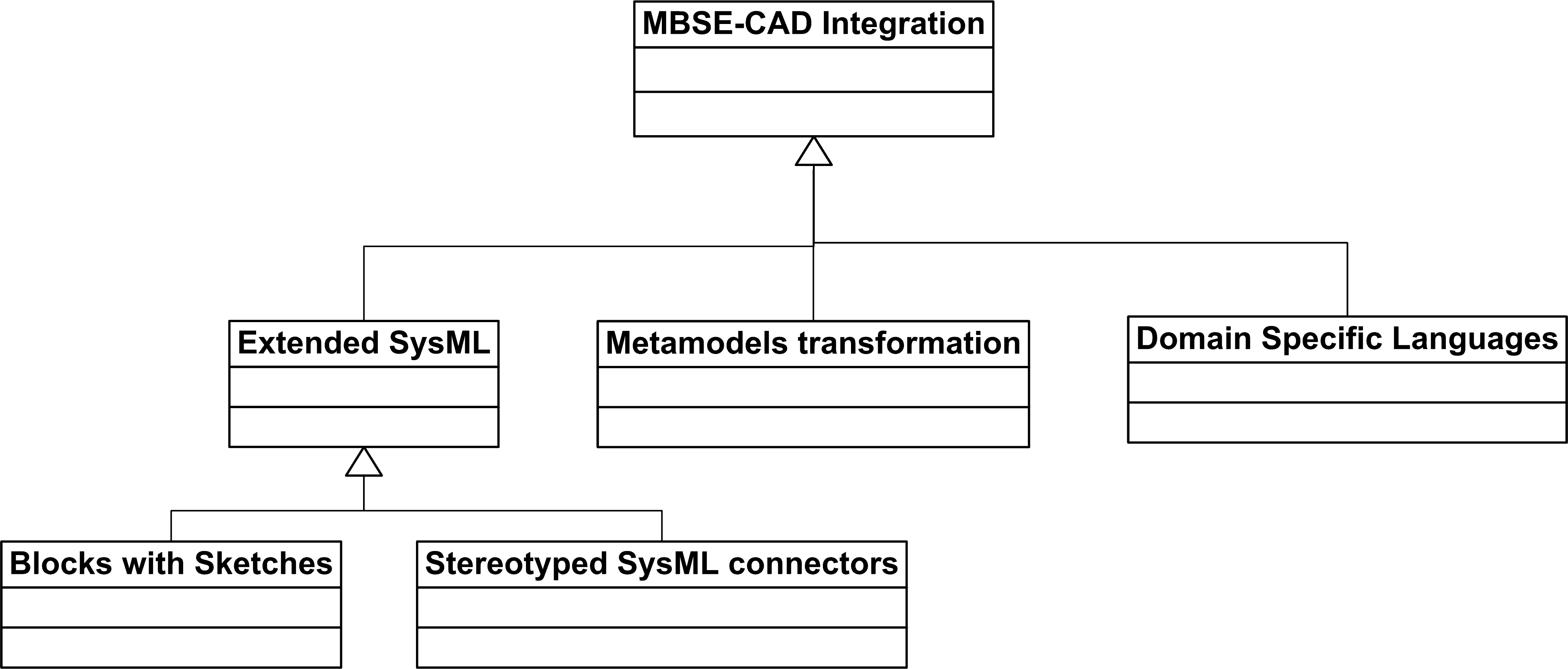
Figure 1: MBSE (SysML) – CAD Integration Approaches
IV. Examples of integration alternatives
One approach proposed by Grundel and Abulawi proposes the extension of the SysML blocks, adding a block compartment where they represent sketches that are less detailed engineering representations than CAD models. Sketches facilitate the communication of design ideas and allow evolving them. Grundel and Abulawi developed the so called SkiPo (Sketch and Port) model. In SkiPo, a block contains diverse compartments: one for the functional description, another for the sketch area including sketches or pictures, and a third one, the block area where the solution can be specified by describing specific properties or decomposing it into subordinate blocks (Grundel and Abulawi, 2016).
A sketch always contains geometry details but other types of constraints can be documented as well, such as materials specifications and joining techniques.
Alberts and Zingel propose an extended SysML profile based on the Contact&Channel-Approach (C&C2-A) for integrated modeling of functions and including physical properties of physical systems. One of the rules for the consistent application of this approach states that every system and subsystem can be described by the basic elements Work Surface Pair (WSP) for two elements being in contact, Channel and Support Structure (CSS) and Connector (C). From functional flows represented by activity diagrams with partitions, the CSSs are generated automatically by a plugin of the prototype tool they developed. When the CSS are created, the structure can be modeled using SysML Internal Block Diagrams with stereotyped SysML connectors to network WSs (Alberts and Zingel, 2013). They propose to apply C&C2-A combined with the Functional Architectures for Systems (FAS) MBSE method (Lamm and Weilkiens, 2010).
Other approaches are based on metamodel transformation. A metamodel would be a textual, graphical, and/or formal representation of the modeling concepts used by a tool and how they are linked. It is known that SysML/UML are defined by a metamodel; the MOF 2.5 specification provides the basis for metamodel definition in OMG’s family of modeling languages including the UML and is based on a simplification of UML 2’s class modeling capabilities. CAD tools such as Solid Edge have metamodels supporting the modeling concepts which are generally supported by mechanical CAD tools. As is represented in Figure 2, if it is possible to create a map between metamodel concepts, then a transformation language and a transformation tool between models can be developed. We applied this approach for the use of the Cheddar tool for performance assessment of the PPOOA software architecture models as described in a previous paper (Fernandez and Marmol, 2008). Qamar proposes a metamodel transformation approach to be applied to transform Solid Edge CAD models into SysML models. To facilitate the mapping, they extended SysML, because it lacks formal and detailed semantics needed to build the mapping relations with sufficient semantic depth. The created SysML profile for Solid Edge is used to model dependencies between the SysML and the Solid Edge models. The Atlas Transformation Language (ATL) is used to read the model conforming to the Solid Edge metamodel and writes the target model conforming to SysML profile for Solid Edge (Quamar et al., 2015).
Scheffler et al propose using metamodels to allow export CAD models transformed into an XMI format of a SysML model (Scheffler, R. et al., 2016).
In some cases, as described by Qamar, the dependencies captured by modeling the correspondence relationships between models as described above, do not provide information about the type of dependency and when it is applicable. So they propose an approach where they use a Domain Specific Modeling Language to provide the necessary dependency modeling features. A dependency here is a causal relationship between two or more properties. They model two types of dependencies: synthesis dependency whose outputs are synthesis properties, and analysis dependency whose outputs are analysis properties. As soon as a design concept is captured, dependencies between the views are captured inside the dependency model (Qamar et al., 2015).
Similar approaches as those described above are to be taken for the Electrical Computer Aided Design (ECAD) where a SysML profile for ECAD modeling is proposed, where concepts such as black box, cable, conductor, connector, cavity, contact, and tool are considered (Cabot, 2018).
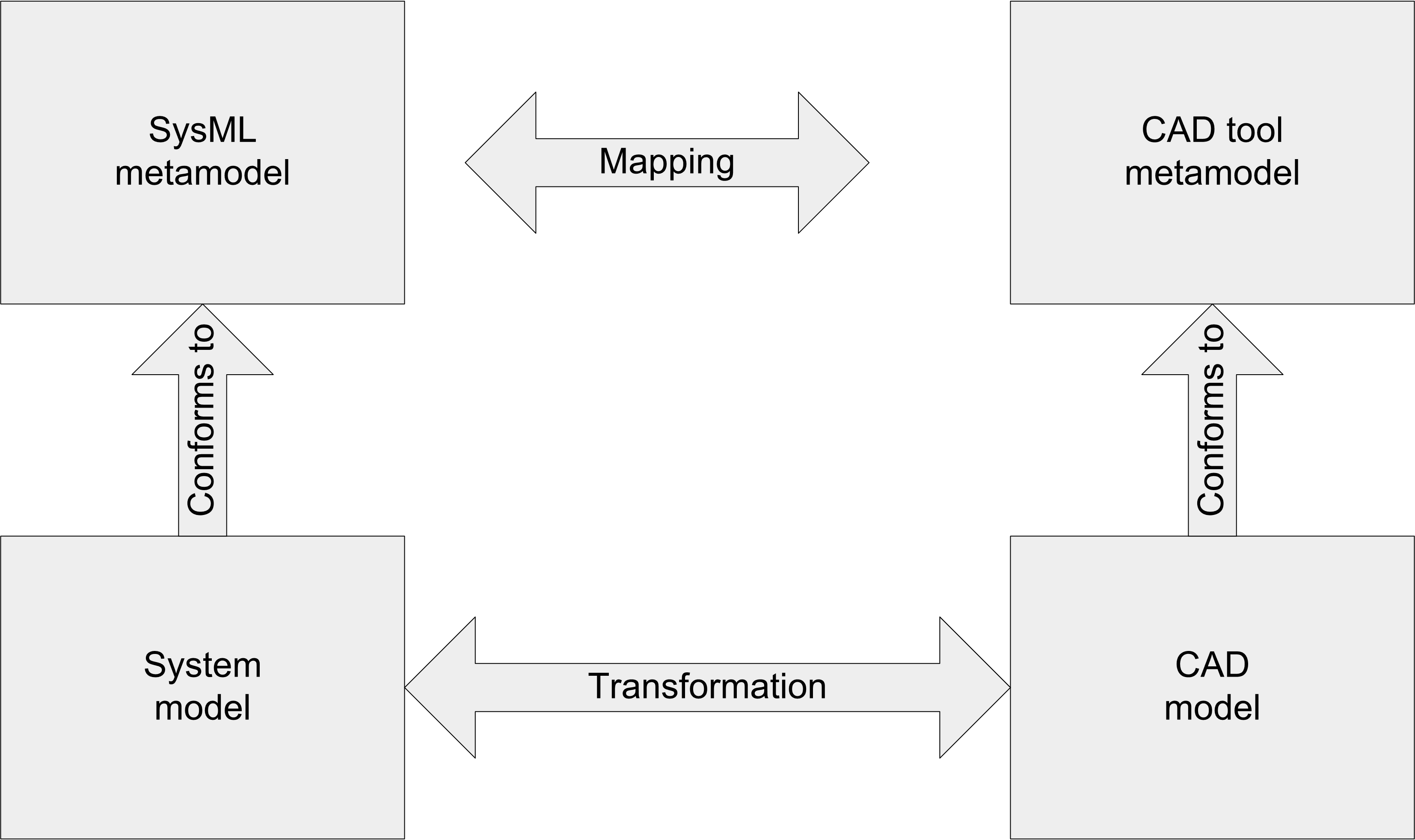
Figure 2: Metamodel-based Transformation of Models
Summary and Conclusions
One of the main concerns of Model Based Engineering is the integration of disparate models from diverse specialties.
There are differences in the abstraction levels of the systems engineering models, frequently represented in SysML notation and the CAD tools models for mechanical design. These differences make it difficult to establish associations between both types of models.
A literature search identified three main groups of integration approaches. These approaches are based either in the extension of SysML notation, the transformation of metamodels from MBSE to CAD, or the use of Domain Specific Languages (DSL).
Considering the differences between these integration approaches and the tools supporting them, the interested reader may plan his/her roadmap to apply them.
List of Acronyms Used in this Paper
Acronym Explanation
ATL Atlas Transformation Language
CAD Computer Aided Design
C&C2-A Contact&Channel-Approach
CSS Channel and Support Structure
DSL Domain Specific Language
ECAD Electrical Computer Aided Design
MBE Model Based Engineering
MBSE Model Based Systems Engineering
MOF Meta Object Facility
ISE&PPOOA Integrated Systems Engineering and Pipelines of Processes in Object Oriented
Architectures
OMG Object Management Group
SkiPo Sketch and Port
SysML Systems Modeling Language
UML Unified Modeling Language
WS Working Surface
WSP Work Surface Pair
XMI XML Metadata Interchange
XML Extensible Markup Language
References
Albers A. and C. Zingel , “Extending SysML for Engineering Designers by Integration of the Contact & Channel – Approach (C&C2-A) for Function-Based Modeling of Technical Systems,” Procedia Computer Science, Volume 16, 2013, Pages 353-362, ISSN 1877-0509, https://doi.org/10.1016/j.procs.2013.01.037.
Bishop, R.H. (Ed). Mechatronics. An Introduction. Taylor & Francis Group, Boca Raton, FL, 2016.
Cabot, J. SysML extension for ECAD (Electrical Computer-aided Design). https://modeling-languages.com/sysml-extension-ecad-electrical-cable-design/ (accessed June 25, 2019).
Fernandez, J.L. and C. Hernandez. Practical Model-Based Systems Engineering. Artech House, Nordwood, MA, 2019.
Fernandez J.L. and G. Marmol, “An Effective Collaboration of a Modeling Tool and a Simulation and Evaluation Framework”. INCOSE International Symposium, 18: 1509-1522. doi:10.1002/j.2334-5837.2008.tb00896.x.
Grundel, M. and J. Abulawi, “SkiPo – a sketch and flow based model to develop mechanical systems.” INCOSE International Symposium, 26: 399-414. doi:10.1002/j.2334-5837.2016.00168.x.
Lamm, J.G. and T. Weilkiens, “Functional Architectures in SysML.” Proceedings of the Tag des Systems Engineering (TdSE ’10). Munich, Germany, 2010.
Mhenni, F. et al., “A SysML-based methodology for mechatronic systems architectural design,” Advanced Engineering Informatics. (2014), http://dx.doi.org/10.1016/j.aei.2014.03.006.
Qamar, A., Wikander, J. and C. During. “Managing dependencies in mechatronic design: a case study on dependency management between mechanical design and system design.” Engineering with Computers (2015) 31: 631. https://doi.org/10.1007/s00366-014-0366-x.
Scheffler, R. et al., “Graphical Modelling of a Meta‐Model of CAD Models for Deep Drawing Tools.” INCOSE International Symposium, 26: 1090-1104. doi:10.1002/j.2334-5837.2016.00213.x.
About the Author
 Jose L. Fernandez has a PhD in Computer Science, and an Engineering Degree in Aeronautical Engineering, both by the Universidad Politecnica de Madrid (UPM,) Spain. He has over 30 years of experience in industry as system engineer, project leader, researcher, department manager, and consultant. He was involved in projects dealing with software development and maintenance of large systems, specifically real-time systems for air traffic control, power plants Supervisory Control and Data Acquisition (SCADA), avionics and cellular phone applications.
Jose was associate professor at the E.T.S. Ingenieros Industriales, Universidad Politecnica de Madrid. His areas of interest were systems engineering, real-time systems, software engineering, CASE tools, and project management. He is the methodologist of the PPOOA architectural framework for real-time systems and ISE&PPOOA, an integrated systems and software MBSE methodology for complex systems.
Jose has more than 50 publications in international journals and conference proceedings, mainly in the fields of systems engineering, software development, real-time systems, and project management. He is senior member of the IEEE (Institute of Electric and Electronics Engineering) and member of INCOSE (International Council on Systems Engineering), participating in the software engineering body of knowledge, systems engineering body of knowledge, and requirements engineering working groups of these associations. He is a member of the PMI (Project Management Institute), participating as reviewer of the PMBoK 6th Edition, 2017 and the Requirements Management Practice Guide, 2016.
3.1 Updates in the Evolution of Systems Engineering
by
Steven H. Dam, Ph.D., ESEP
Email: steven.dam@specinnovations.com
Abstract
In January 2018, the International Council on Systems Engineering (INCOSE) began an initiative called FuSE – the Future of Systems Engineering Initiative. In 2011, we began thinking about this, following a presentation by Dr. Michael Ryschkewitsch, who at that time was the NASA Chief Administrator. His presentation: “NASA Systems Engineering Challenges” provided a set of “uses and challenges” for systems engineering. Many of those challenges mirror the intended outcome for the FuSE initiative as stated by the President of INCOSE, Mr. Gary Roedler: “evolving systems engineering that enables us to leverage the new technologies that drive us fully into a dynamic, nondeterministic, and evolutionary environment.” As a result of Dr. Ryschkewitsch’s paper, the Lifecycle Modeling Language (LML) and Innoslate® tool were developed to respond to those challenges. This paper will show how many of the ideas and goals of the FuSE Initiative have already been accomplished, so that in part the future of systems engineering is already here.
Introduction
On April 15, 2011, I attended a Conference on Systems Engineering Research (CSER) event where Dr. Michael Ryschkewitsch presented his paper entitled “NASA Systems Engineering Challenges.”[1] Three parts of his future vision included: Model-based Artifacts; Seamless Data Flow; and Distributed Teams. He also discussed how the uses and challenges vary throughout the lifecycle. In this slide he presented a number of questions including: “How to enable modeling that provides the needed fidelity yet can be done quickly and cheaply?”; “How do we develop the standards that allow lossless integration across organization and tool boundaries?”; and “How do we make the full suite of information captured during design and development available to the operators without having prior knowledge of their needs?”
We had begun exploring the development of a desktop tool for systems engineering. I had used several software and systems engineering tools in the past 25 years (at that time), including many different systems engineering tools: a Data Flow Diagramming tool, a State Machine tool, RDD-100, CORE, CRADLE, DOORS, and Systems Architect but we had seen that these tools had stagnated, not evolving with the new technologies and approaches. The new tools coming into the discipline were focused on UML and more recently at that time SysML. These tools required knowing a language and concepts that were unfamiliar to most systems engineers, let alone the broader set of stakeholders with whom we must communicate.
It was clear from Mike R’s (as he liked to be called) presentation that we needed to embrace one of the emerging technologies of the time: cloud computing. Cloud computing enables distributed, collaborative teams. It also provides speed and computational power as needed to perform complex modeling and simulation quickly and cheaply. As such, we scrapped our desktop software development and began exploring cloud technologies.
But just solving the distributed teams’ part of the problem did not completely address the other two parts of Mike R’s vision: Model-based Artifacts and Seamless Data Flow. To get to those, we had to take a close look at the language. SysML was not the answer, so what was? To best understand why not SysML, it helps to explore the past language developments.
History of Systems Engineering
Some believe systems engineering can be traced back thousands of years. The wonders of the world, such as the pyramids of Giza, Ziggurat at Ur, Treasury of Atreus, and the Great Wall of China,[2] could only have been designed and built systematically. Others trace it back to the “Machine Age.” Clearly the industrial revolution and the assembly lines required systems thinking. But by the “Space Age”, systems engineering as we know it was clearly born. Clearly “systems of systems” thinking was required by this time. Many people ascribe the modern age of systems engineering to Ramo and Woolridge, which became TRW, which is now part of Northrop-Grumman. They were the lead contractor for the “Atlas Project,” that resulted in the first Intercontinental Ballistic Missile (ICBM). This project required over 18,000 scientists and engineers. A systemic approach was essential to deal with the size and scope of this project, since it was not only the missile itself, but also the basing system and command and control. Even the ICBM is only part of a larger strategic offensive capability, dubbed MAD (Mutually Assured Destruction). A little later, TRW also aided in the development of a strategic defensive system called Project Safeguard. As part of that development, TRW personnel developed the Systems and Software Requirements Execution Model (SREM) approach. It consisted of an ontology and executable diagrams called behavior diagrams. SREM evolved over time and was used as the basis for a number of government-developed tools and commercial tools, including RDD-100 and CORE. These were called Computer-Aided Systems Engineering (CASE) tools.
Meanwhile, many software development approaches came and went. In the1960s we used flow charting techniques for diagramming software. In 1970, Data Flow Diagramming (utilized by Yourdon-DeMarco and Ward & Mellor) became popular. In the 1980s we had the Integrated Definition (IDEF) diagrams, as well as State Machine modeling. In the1990s, Object-Oriented Analysis and Design, which lead to UML. All these modeling techniques were primarily used for software development, but many of us attempted to apply them to systems engineering as well. We even used the Computer-Aided Software Engineering (CASE) tools for this purpose, with limited success. In each case, the systems engineering community seemed to adopt the software technique soon before it became unpopular in the software community.
SysML was developed in the mid-2000s as a profile on UML. Although, several SPEC personnel and I had significant experience in the Java object-oriented programming language, we really did not envision that approach fitting well with system engineering. Our programmers, who had received their degrees from one of the top Computer Science departments in the US, had very little familiarity with UML and had never heard of SysML. When I asked them why they didn’t know UML, they did what all of today’s computer scientists do: they “Googled” it. The graph in Figure 1 was and still is the result. Since the timeline in the graph does not start until 2004 and UML was first introduced in late 1997, we don’t know when the interest peaked, but this graph clearly shows a decreasing trend in the use of UML. A similar query of SysML shows a flat line.
Why has the software world lost interest in UML? One reason may be the same as what we found with flow charting and these other previous modeling techniques: it’s a lot faster and easier to write, debug, and execute the code than it is to draw the drawings. So, the diagramming techniques tended to be used more to document the code than design it. If it is used first, then usually you find that the models developed lacked much of the critical information needed for software development, because they are only an abstraction of the software.
Figure 1: Interest in UML has decreased significantly in the last 15 years.
The modern software tools provide automatic checking for syntax, code repositories, and debugging tools that far exceed what they can get out of any of the modeling tools. With Agile Software Development approaches, they only want the functional requirements, so why are we in the systems engineering world so focused on providing diagrams the software developers don’t want? How do we move into the future with a technique that can leverage the technologies of today and tomorrow, while producing the products needed by all stakeholders, not just software developers? These and other questions are being posited by the INCOSE FuSE Initiative.
INCOSE’s Vision of FuSE
According to the INCOSE Charter[3] for this working group, the purpose of FuSE is to:
- Position systems engineering to leverage new technologies in collaboration with allied fields.
- Enhance the systems engineer’s ability to solve the emerging challenges.
- Promote systems engineering as essential for achieving success and delivering value.
In the briefing presented at the INCOSE International Workshop this year,[4] they also asked these questions and answers:
Q: What will “good” look like when we have used FuSE to deliver systems?
- Methods, processes, techniques for self-learning systems (including process changes and handling V&V) will be provided.
- Improved simulations to handle dynamic objectives will be available.
- Architecture techniques for AI heavy systems will be provided.
- It will be demonstrable how AI positively improves a system while considering “ilities” (i.e., Safety/Security) within acceptable bounds.
Q: What’s stopping us from doing this now?
- Data availability/usage (OCI and IP concerns).
- Knowledge and research.
- Assurance, trust, and understanding of the technologies.
- SE is too slow to keep up with AI advancements.
These questions and their answers require a fair amount of analysis to fully understand what they entail, but they all seem to be very focused on artificial intelligence, as if that was the only technology of interest. The real underlying problem is that SE is too slow. We take months and years to do what should only take weeks to months. If we resolved this issue, the rest might become much easier.
Why is SE Today Too Slow
The whole idea of model-based systems engineering (MBSE) was to speed up the process by having designers focus on the models, which would produce not only the documentation, but in the case of software, the code itself. INCOSE and others believed that SysML was the answer to MBSE. As we saw earlier, UML has lost the interest of many in the software development field, therefore that path to code is not ideal. And of course, that approach misses the other critical parts of the system: people, hardware, test facilities, etc. But the problem is more fundamental. Systems engineering deals with the design at a certain level of abstraction. We develop the requirements for the systems, not the detailed designs of the components. When we try to push our methodologies and approaches into the design engineering space, those methodologies would have to subsume all the other disciplines. In other words, we would have to be able to accurately describe the details of computer-aided design tools, electrical engineering diagrams, software (in all the possible languages), etc. That’s not our job. Our job is to optimize the cost, schedule, and performance at the system level. So, can SysML do this or is there something missing in that approach?
To help answer that question, we need to identify what is needed. We need:
- Methods to capture and visualize tremendous amounts of information.
- Massive storage and retrieval of information.
- The capability to move data around easily, between applications.
- A language that enables decomposition and abstraction:
- A systems engineering language, not a software engineering language;
- A language that is simple so that systems engineering can easily use it; and
- A technical and programmatic language so we can optimize cost, schedule, and performance for the system.
SysML may be a lot of things, but no one thinks it’s simple and easy to understand by all stakeholders. Also, a language cannot deal with the needs noted in the other bullets above. Those bullets relate to the technologies and tools we need to use to implement the language.
Lifecycle Modeling Language (LML)
To address the language problem, several people formed the LML Steering Committee[5] to create LML as an open standard. This group included systems engineering professors and expert systems engineers from both large and small corporations. The Steering Committee is led by Dr. Warren K. Vaneman[6], a retired US Navy Captain who is also a Professor of Practice at the US Naval Postgraduate School (NPS). In 2012, the group published the first LML specification. The second iteration (version 1.1) was released in 2014 and included an ontology for SysML. The language includes technical information classes (Action, Asset, Conduit, Requirement, etc.) and programmatic classes (Artifact, Cost, Risk, Time, etc.). In all, 12 primary classes and 8 subclasses form the base language. Another class (Equation) and subclass (Port) were added in version 1.1 for SysML. Almost all the classes are related to each other and there are several relationships between the classes. All the relationships use the same verb form for the relationship and its inverse (i.e., decomposed by/decomposes). Also, attributes are provided for each of the classes and many of the relationships. In this way, the language is well defined with the nouns (classes), verbs (relationships), adjectives (attributes on the classes), and adverbs (attributes on the relationships). In this way, LML provides a robust base language. It is advertised as the “80% solution” in that it is only meant to be a common language for everyone to use. You can easily extend it to other domains or to enhance data capture, but if you use it as a basis for the language it will be easier for others to use and understand.
LML requires only three diagram types (Action, Asset, and Spider) to represent the functional model, physical model, and traceability, but it recommends using other common diagrams for visualizing the information, such as timelines, hierarchies, risk matrices, etc. Even the Action Diagram has only one truly unique feature: it replaces the usual logic symbols used in other languages with a special type of Action. This special type of Action represents the decision points and can be traced to the Assets that perform them, thus enabling us to design in the controls needed for command and information assurance deep into the design.
To read more concerning LML, one can obtain the specification for the website[7] or read Essential LML[8]. More books and papers are available or will be available soon.
How Can We Use the Technology Advancements
So now that we have the “language of the future,” let’s look at the available technologies and tools to help us with the other needs identified above.
Clearly cloud computing technologies will help us deal with the need for “massive storage and retrieval of information.” Public, private, and hybrid clouds are available everywhere now. Amazon Web Services (AWS) and Microsoft Azure appear to be the current leaders in this technology. Google AppEngine was the early favorite, but they seem to have dropped behind AWS and Azure, at least in the US Government space.
This technology also helps us deal with the capture part of “methods to capture and visualize tremendous amounts of information.” The visualization is trickier in that it requires using modern diagramming techniques and types, such as the sunburst diagram or using numbers to replace objects in a diagram. Most people want to see typical diagrams, such as the hierarchy, but for a major system, that diagram ends up with tiny boxes even on a large plotter. The spider diagram can have the same effect. So, tool developers usually provide ways to limit the information on a diagram by levels or relationships or decomposition. As long as the diagrams are generated from the database and not separately drawn, the visualization “problem” becomes lessened. Unfortunately, most of the tools available today do not use “concordance”[9] as a means to generate the diagrams from the data. Tools with this capability have been around for many years, including RDD-100, CORE, Cradle, and Innoslate. So again, this technology is available today.
The “capability to move data around easily, between applications” comes from having a common language and application programmer interfaces (APIs). A common language is needed to be able to translate between different classes of information. LML provides this capability today. It has been mapped to other languages, such as the DoDAF Metamodel 2.0 and SysML.[10] APIs also exist today, and most tools implement them as a means of communications. Again, a solution exists with current technologies if everyone wants to use it. The real problem has been that the vendors keep their ontologies proprietary. Innoslate uses LML, which is an open ontology. The XML generated by Innoslate can be easily understood since an XSD also is available.
In summary, the basic needs are addressed by current technologies. Next, let’s address that the major technology seems to be driving the concern about artificial intelligence.
Modeling and Applying AI
As part of a presentation on the “Shaping Systems Engineering for the Future” Mr. Garry Roedler showed the chart provided in Figure 2.
The top and bottom items particularly refer to AI as being an area of concern. So how do we model AI behavior? It is clearly “dynamic, non-deterministic, and evolutionary,” but so are people. We have all those same features and properties. In systems engineering, we spend a significant amount of time and energy in modeling human behavior. We usually want to use the system to channel that behavior in a particular direction – positive for the goals of the mission. We model human behavior using probabilistic models that are calibrated by real-world experience and experiments. With LML, we can allocate the decision points to whatever performs that Action, including AI components. The decision points also provide a mechanism to embed cybersecurity and information assurance features into the design at all levels, thus addressing the second item in Figure 2 as well.
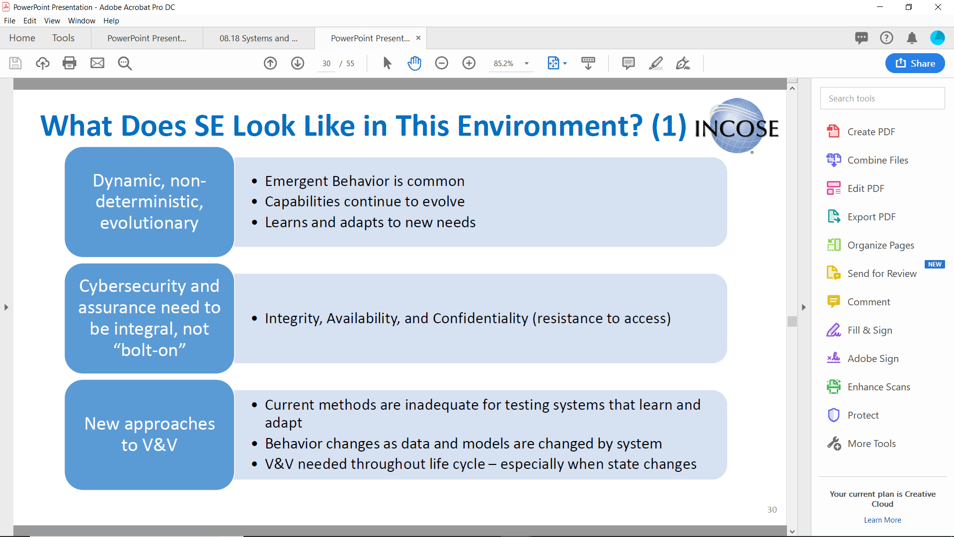
Figure 2: Slide from presentation by Mr. Garry Roedler.
Concerning the V&V issues in Figure 2’s third item, since we can develop automated tests, those tests can use AI components as well to aid in the testing. For instance, we have used AI technologies (Natural Language Processing and Machine Learning) to aid in determining requirements quality, modeling quality, and traceability. We use those technologies today in Innoslate. In a sense, we are in fact conducting early V&V using this technology.
Since Innoslate extends LML by using a subclass of the Action (Test Case), we can also model our test processes at the same time. We can then identify where and how to use AI techniques to aid in conducting the tests themselves. Further exploration of this capability will be conducted by SPEC Innovations, the tool developer, and many of the Universities that use Innoslate as a research tool. With Innoslate’s APIs we can push the boundaries of today’s technology limitations in preparation for new technologies. SPEC Innovations provides an Academic version of the tool that is only limited by the number of entities in an Innoslate project. Researchers can and are using the APIs to enhance our understanding of systems engineering. We at SPEC Innovations support such efforts.
MBPM and Model-Based Reviews
The programmatic features of the LML language also enables model-based program management (MBPM). This capability comes from the recognition that the program manager also optimizes cost, schedule, and performance for the program, just as the systems engineer does for the system. Both also work to mitigate risk in these areas. Innoslate implements these features for program managers and provides views, such as the Risk Matrix and Timeline Diagram. The Action Diagram also can be used to model the program processes. By putting in timing and resource estimates, the program manager can derive the overall cost, schedule, and performance from the discrete event and Monte Carlo simulations. The Monte Carlo distributions also provide a measure of the potential for schedule slippage or cost overruns. These measures can be translated into risk probabilities for the overall program.
Another area often pointed to as a need in the future is the idea of Model-Based Reviews (MBR). An MBR means never actually printing out the program documentation, but instead having reviewers inspect the model. But most reviewers will not be experts in either the modeling or the tool. So to accommodate them, Innoslate provides documentation in the Documents View. So reviewers can read the documents within Innoslate and provide comments using the commenting tool. All you have to do is provide the reviewers with: 1) access to the tool; 2) a hyperlink to the document(s) you want them to read; and 3) explain how to use the sidebar to provide comments. Innoslate has been used for over five years to conduct these kinds of reviews and has even been used in a training course[11] for all the NASA milestone reviews, demonstrating that this technique can be used throughout the lifecycle.
Summary
Updates in the Evolution of Systems Engineering have provided a mechanism to propel systems engineering into the future of digital engineering. LML provides a strong ontology and diagramming framework to model complex systems, including those that use AI technologies. As a cloud-native tool, Innoslate implements LML and goes beyond the current standard to provide a seamless, integrated, collaborative environment for program management, systems engineers, and other stakeholders to work together and provide the necessary legal products required by any lifecycle process.
About the Author
Dr. Steven H. Dam is the President and Founder of Systems and Proposal Engineering Company (SPEC Innovations). Dr. Dam has a BS degree in Physics from George Mason University and a PhD. in Physics from the University of South Carolina. He has been involved with structure analysis, software development, and systems engineering for over 30 years. He participated in the development of C4ISR Architecture Framework and DoD Architecture Framework (DoDAF), the Defense Airborne Reconnaissance Office (DARO) Vision Architecture, the Business Enterprise Architecture (BEA), and Net-Centric Enterprise Services (NCES) architecture. He has also been a long-term member of INCOSE and was a Past-President of the San Diego Chapter before relocating to the Washington Metropolitan Area. Dr. Dam has presented numerous papers and seminars to the WMA Chapter. He is currently a Past-President and Programs Chair of the WMA Chapter of INCOSE.
3.2 The Role of Requirements in an MBSE World
by
Lou Wheatcraft
Requirements Experts/Seilevel
Email: Louw@reqexperts.com
Website: http://www.reqexperts.com
Copyright © 2019 by Lou Wheatcraft. All rights reserved.
Abstract
The overall theme of the International Council on Systems Engineering (INCOSE) Requirements Working Group (RWG) for the 2019 International Workshop (IW2019), “The role of requirements in a Model-based Systems Engineering (MBSE) world”. was very popular among the attendees. Based on this theme there were ten presentations, resulting in a good cross section of perspectives and insights. While many good points were made over the four days, several key insights emerged. This article addresses five insights that resulted from the presentations and discussions.
Introduction
The format of the sessions was such that questions and comments during the presentations were encouraged, resulting in interesting and engaging discussions. The presentations during the RWG sessions at IW2019 addressed the ongoing debate concerning the roles requirements play in a MBSE world:
- Are text-based requirements still needed given the increased focus on diagrams, use cases, and models?
- Can models be used to both help define requirements as well as implement those requirements in design?
- Can models be used to improve the quality of requirement completeness, consistency, and correctness?
The focus of most of the presentations was on how systems engineering tools (requirements management tools as well as modeling tools) can be integrated together, resulting in an overall model of the system of interest that includes both text-based needs and requirements along with diagrams and models developed as part of the definition and design processes. The presenters showed how their organizations were able to practice information-based requirement development and management (I-RDM) at the beginning of the project and then use the resulting data and information as inputs to the Model-based Design (MBD) activities and artifacts (See Insight 4). The result demonstrated that the capability exists to link artifacts developed in one lifecycle phase to artifacts in other life cycle phases. Thus, needs can be linked to the stakeholders and concepts that were developed to address stakeholder expectations. Requirements developed and managed within a requirement management tool (RMT) can be linked to those needs as well as to the design models developed and managed within existing modeling tools, to the physical design, as well as to system verification and validation activities and artifacts.
Among the key insights that emerged during the presentations and resulting discussions that seem particularly significant to me are the following:
- The concept of “duality” as applied to requirements and models. Depending on what is being done and what is being communicated, textual requirements and models are two sides of the same SE coin. Neither is solely sufficient – both are needed!
- Requirements don’t just happen – they are a transformation from a set of needs that were transformed from a set of concepts that address a feasible solution to a problem.
- The quality of the requirements is directly proportional to the quality of the set of stakeholder needs from which they were transformed. Likewise, the quality of the set of needs is directly proportional to the quality and quantity of the work done to define the problem, understand the stakeholder expectations, drivers and constraints, and risks – as well as the time and effort spent in maturing a feasible logical and physical concept (model) based on this information prior to documenting the needs.
- Preliminary conceptual and physical design architectural models are both the source of the stakeholder needs and resulting requirements (design inputs) as well as the tools used to implement those same sets of needs and requirements, in the form of the design and the engineered system of interest (design outputs).
- 20th century systems engineering (SE) methods and practices are often not adequate to address the challenges of increasingly complex, software centric systems of the 21st century!
The following discussion explores each of the above insights in more detail.
Insight 1
A key insight from IW2019 was the concept of “duality” as applied to requirements and models:
1) Text-based requirements are important and cannot be replaced by diagrams/models.
2) Diagrams/models are also important and cannot be replaced by text-based requirements.
Both are different sides of the same SE coin! Neither is solely sufficient – both are needed!
Text-based Requirements
For many ideas and concepts that need to be communicated; well-formed, text-based needs and requirements have been proven to be the most effective form of communication. Advantages2,5,6 of text-based requirements include the following:
- Communication. There is still (arguably, there will always be) a sizeable audience who cannot interpret, do not understand, or who are not willing to work with, diagrammatic or other non-textual representations of needs or requirements, especially when the words used (technical jargon) are not intuitively obvious to the reader. These people, particularly the customers and users of the system, may not have been trained in language-based models or may not find the terminology used in some diagrams and models to be intuitive. When that is the case, effective communication4 has not taken place since the receiver of the message may not interpret and understand the message as intended by the sender and may well lose interest in the needs and requirements elicitation activities. On the other hand, text is universal. Of course, the text-based statements have to be well-written in such a way as to be clear, correct, and unambiguous; but then diagrams have even more potential to be unclear, incorrect, and ambiguous if they are poorly formed, defective, or the wrong meaning is assigned to them. Diagrammatic or model representation will almost always have to be supported by well written detailed textual statements in order for the representations to be understood unambiguously.
- Power of expression. There is a wide variety of types of needs or requirements that must be expressed. Use cases, user stories, scenarios, diagrams, and models tend to focus on the functional architecture and may be capable of expressing functional, performance, and interface requirements, but are not presently well suited to expressing non-functional requirements that deal with the physical architectural elements associated with quality (-ilities), regulations, standards, and physical characteristics. Textual forms carry the universal power of expression of natural language for all types of needs and requirements.
- Accessibility. Even when stakeholders are willing to spend the time to learn modelling languages such as UML and SysML or other model-based tools, the SE tools (including requirements management tools (RMT)) and modelling tools used to create and view the data and information represented by the model’s dataset are not readily available and assessable to all stakeholders. In many cases, access is restricted by the number of “seats” or “licenses” purchased. Being able to provide needs and requirements in an electronic document format (pdf, or common office application formats) allows the stakeholders to view the needs and requirements in applications that have been installed on their workplace computers. In addition, there are still managers who still prefer, and demand, printed, text-based documents, and will continue to do so for the foreseeable future.
- Attributes. Both the need and requirement expressions include attributes2,3 that can be used to manage them as well as the system under development across all life cycle process activities. While modelling languages allow users to define an entity having the name “attribute” and link that entity to a need or requirement, few practitioners do so. Operational scenarios, use cases, user stories, and other diagrams used to represent needs or requirements are generally not conducive to appending a set of attributes.
- Formal, binding agreement. Text-based requirement statements are more easily understood in a formal agreement or contract-based system development effort by a wider, and often, non-technical set of stakeholders including business management, project management, configuration management, contract administrators, and legal support. Use of “shall” or another term defined to have the same meaning, makes it clear that what is being communicated is formal, the statement is binding, and will be verified. To be part of a binding agreement, especially in a legal contract, the requirements must be expressed formally and configuration managed in a form that 1) makes it clear the statement is binding and 2) has the characteristics of well-formed statements and sets of statements as defined in documents such as the INCOSE Guide for Writing Requirements2.
- System verification and validation. Most formal agreement (contract)-based product development and management processes include system verification (meets requirements) and validation (satisfies stakeholder needs in the operational environment) as formal processes that must occur prior to system acceptance and use. In highly regulated, safety critical industries such as the medical device industry, formal proof that the design outputs, including the product, meet the design inputs is needed prior to the product being released into the market. Currently, no other form, other than textual requirements, has been able to meet these characteristics.
Models and Diagrams
On the flip side of the SE coin, for many ideas and concepts that need to be communicated, models and diagrams have been proven to be the most effective form of communications. Advantages7 of models and diagrams include:
- Defining and maturing concepts: Models and diagrams are excellent methods for defining and maturing a feasible concept by providing a context for requirements and are key to help ensure correctness, completeness, and consistency of both individual requirements and sets of requirements.
- Source of Requirements: As part of concept maturation, functions are defined and relationships between those functions (interactions and interfaces) are identified. From this knowledge, functional flow block diagrams can be developed as well as context diagrams and interface diagrams. These can then be transformed into a functional architecture diagram which can, in turn, be transformed into a physical architectural diagram. These diagrams are an excellent source of requirements.
- Key to understanding: Models and diagrams help facilitate communication by making complex systems and processes easier to understand. As the old saying goes: “A picture is worth a thousand words…”.
- Identify and manage interdependencies. A key tenet of systems engineering is that the behavior of a system is a function of the interactions between the parts of the system. Tying these interactions together can result in an equation of dependent variables. From a change management perspective, a change in one of these variables results in a need to change one of the other variables. Managing these interdependencies within a model is much easier than in document-based approaches to SE.
- Support simulations: Language-based models developed as part of design can be used to develop higher fidelity models that allow simulations of the system. With a simulation capability, design issues can be identified and corrected before actually building and coding the system – saving both time and money.
Insight 2
Requirements don’t just happen – they are a transformation from a set of needs that were transformed from a set of concepts that address a feasible solution to a problem.
The following definitions are based on the INCOSE Guide for Writing Requirements2. Concepts, needs, and requirements apply to an entity, which could exist at any level of the model as shown in Figure 1. Entities apply to any single thing at a given level.
- An entity is a single thing to which a concept, need, or requirement applies: an enterprise, business unit, service, system, or system element (which could be a product, process, human, or organization).
An entity satisfies concepts (validation), needs (validation) and requirements (verification) that are written for the entity as well as satisfy a problem or opportunity identified by the stakeholders. An entity is the subject of both a need statement (“The <stakeholders> need the <entity> to ……..”) and a subsequent requirement statement (“The <entity> shall ……”).
Figure 12: Transformation of concepts into needs into requirements
Defining and documenting concepts, needs, and requirements for an entity is more than just an exercise in writing; it is an engineering activity where the Requirements Engineer (RE) or Business Analyst (BA), through formal analysis, determines specifically what the stakeholders need the entity to do to satisfy a specific problem or opportunity. This formal analysis starts with the RE or BA engaging the customers, users, and other stakeholders in order to formalize a number of concepts which provide an implementation-free understanding of what is expected of the entity (design inputs) without addressing how (design outputs) to address the mission or business goals and objectives within defined constraints with acceptable risk. Concepts can be communicated in various forms including textual or graphical representations.
- A concept is a written or graphic representation that concisely expresses how an entity will satisfy the problem or opportunity it was defined to address within specified constraints with acceptable risk.
There can be a number of concepts that apply to each entity, so it is useful to develop a minimal set of feasible concepts that define the expectations of all entities. It is also useful to provide some structure to the set of concepts. As illustrated in Figure 1, life-cycle concepts include operations concepts, acquisition concepts, deployment concepts, support concepts, and retirement concepts. Concepts, needs, and requirements are developed for entities at all levels. As stated under Insight 1, models and diagrams are very useful and important tools to help define and mature these concepts.
Based on these concepts, the RE or BA then defines a set of needs, that when met, will result in the concepts being realized.
- A need statement is the result of a formal transformation of one or more concepts into an agreed-to expectation for an entity to perform some function or possess some quality (within specified constraints with acceptable risk).
Need statements are written from the perspective of what the stakeholders need the system to do; requirements are written from the perspective of what the system needs to do to meet the needs. Developing requirements is an engineering activity where the RE or BA, through formal analysis, determines specifically what the system must do to meet the needs using a formal transformation process involving either decomposition or derivation.
Requirements at one level are implemented at the next level of the system architecture via allocation. A child requirement is one that has been transformed (derived or decomposed) from an allocated parent requirement; the achievement of the complete set of children requirements will lead to the achievement of the parent requirement. At the system level, the achievement of the system level requirements results in the needs being achieved, from which the system level requirement was transformed.
- A requirement statement is the result of a formal transformation of one or more needs or parent requirements into an agreed-to obligation for an entity to perform some function or possess some quality (within specified constraints with acceptable risk).
Figure 22 shows how the above concepts are related.
Figure 22: Entity-relationship diagram for customers, concepts, entities, needs and requirements terms
Insight 3
The quality of the requirements is directly proportional to the quality of the set of stakeholder needs from which they were transformed. Likewise, the quality of the set of needs is directly proportional to the quality and quantity of the work done to define the problem, understand the stakeholder expectations, drivers and constraints, and risks – as well as the time and effort spent in defining a feasible logical and physical concept (model) based on this information prior to documenting the needs and transforming the into requirements.
These activities are often referred to as scope definition. It is important to define and baseline scope in order to ensure the technical team has defined a feasible concept that has been agreed to by the stakeholders before documenting stakeholder needs and transforming them into requirements.
As shown in Figure 35,7, there is a lot of work to be done prior to writing requirements. Reference 5 goes into detail concerning each of the topics shown in this figure.
Figure 35,7: Scope Definition Activities
Insight 4
Preliminary conceptual and physical design architectural models are both the source of the stakeholder needs and resulting requirements (design inputs) as well as the tools used to implement those same sets of needs and requirements in the form of the design, specifications, and the engineered system of interest (design outputs).
Models and diagrams developed as part of scope definition and concept maturation result in a conceptual model of the system of interest. The conceptual model includes both diagrams and text-based needs and requirements. The conceptual model is an input to the design process. Rather than the design team starting with a set of requirements of questionable quality, they can start with a conceptual model based on an underlying data and information model1 and transform that model (design inputs) into a physical model (design outputs) as shown in Figure 4. In Figure 4, developing an underlying data and information model during scope definition and developing requirements is referred to as Information-based Requirement Development and Management (I-RDM). Using modelling as part of the design process is referred to as Model-based Design (MBD).
Figure 45,7: I-RDM + MBD = MBSE
If you combine the concept of I-RDM (design inputs) with the concept of MBD (design outputs), you get what the author advocates is what the intent of MBSE really is. Thus I-RDM + MBD = MBSE.
During scope definition and concept maturation, the focus is on the problem space (design inputs), defining the stakeholder needs and transforming these needs into a well-formed set of requirements which are linked to a conceptual logical architecture model of the system of interest. The quality of these requirements is high because they are based on a mature, feasible concept and the set of stakeholders needs that is consistent with that concept. To help prove feasibility, initial physical design related activities occur concurrently, maturing the system concept to the point that feasibility in the physical realm has been established, within identified drivers and constraints with an acceptable level of risk.
Insight 5
We are 19 years into the 21st century, yet many are still using 20th century SE methods and practices that often are not adequate to address the challenges of increasingly complex, software centric systems of the 21st century!
Today’s system development environment presents many key challenges7 as a result of increases in:
- complexity
- the role software has in the system architecture (software centric systems are the norm)
- dependencies between key parts of the system
- oversight
- competition
- program and project risks
- development risks
- manufacturing risks
- operational risks
- the number of programs that are over budget
- the number of programs experiencing schedule slippage
One answer to these challenges is better systems engineering! Specifically, organizations need to7:
- Incorporate systems thinking[12] into all phases of product development. Due to the complexity of today’s systems, we need to manage system development from a system thinking perspective at the systems level. We need to focus on interdependencies of the parts that make up the system and manage them at the system level. This is especially true when allocating performance and resources between parts of the system. In order to optimize the overall system, we may need to sub-optimize the parts that make up the system. This optimization must be managed at the system level.
- Move software up in the system’s architecture hierarchy. Systems engineering in the 20th century tended to be mostly hardware centric and systems engineering practices worked well with physical architectures that were mostly hardware and mechanical. Today, many of the systems are software centric with system level functionality and performance implemented more in software than in hardware/mechanical parts. Because of this we need to move from a hardware-centric view to a software-centric view. Rather than decomposing a system into subsystems at the second level of architecture, a more appropriate approach may be to allocate system level requirements to hardware, mechanical, and software at the second level and then decompose them into an architecture that is appropriate to the domain and product line.
- Communicate requirements at the proper level. Referring to Figure 4, a major issue with requirements is that it is common to include the how/build-to/code-to design output requirements in the what/design-to design input set of requirements. Or another way of referring to the issue is that it is common that “below the line” requirements are incorrectly communicated in the “above the line” set of requirements. When communicating the how (below the line/design outputs), often the what/why (above the line/design inputs) are not being communicated to the design team. This practice stifles innovation and can overly constrain the design team and force it into a design solution that may not be the best solution.
Recognize the importance of well-formed requirements and sets of requirements. Organizations need to recognize the importance of well-formed and managed requirements to the success of a program/project. Numerous studies8 have shown the increased risk to projects due to poorly developed requirements. As stated in the earlier insights discussion, organizations need to define scope and stakeholder needs before developing requirements, identify a feasible concept before developing needs and requirements, and use diagraming and modelling to help ensure completeness, consistency, and correctness of stakeholder needs and resulting requirements.
- Forms of communication4. As part of the duality principle[13], organizations need to understand the role of both requirements and diagrams and models as well as which form is best to communicate a specific thing to a specific audience.
Summary and Conclusions
These insights are important to understand and implement in all our systems engineering activities to help successfully develop increasingly complex, software-centric systems. Being bound to the old 20th century, document-centric approaches to systems engineering is a recipe to failure. To be successful in the 21st century, we must move to a data-centric approach1 to systems engineering using both text-based as well as diagram and model-based communications, depending on what is being communicated and to whom. Using a data-centric approach, systems engineers should practice system engineering from the perspective that requirements, along with all work products (models, designs, documents, diagrams, drawings, etc.) generated during the performance of system life cycle process activities, are visualizations represented by underlying sets of data and information. To help ensure consistency, these sets of data and information need be able to be accessible and shared between the organizations involved in developing the system of interest. This sharing will help to ensure consistency, correctness, and completeness of work products developed across all system life cycle stages.
Referring back to the questions at the beginning of the article, the answer to all is YES! Based on the duality principle, depending on what is being done and what is being communicated, textual requirements and models are two sides of the same SE coin. Neither is solely sufficient – both are needed!
List of Acronyms Used in this Paper
Acronym Explanation
BA Business Analyst
INCOSE International Council on Systems Engineering
I-RDM Information-based Requirement Development and Management
IS International Symposium
IW International Workshop
MBD Model-based Design
MBSE Model-based Systems Engineering
PM Project Management
RE Requirements Engineer
RMT Requirements Management Tool
RWG Requirements Working Group
SE Systems Engineering
SysML Systems Modeling Language
UML Universal Modeling Language
Acknowledgements
The author would like to acknowledge and thank all those who attended, presented, and actively participated in the discussions during the four days of RWG meetings at IW2019! It was all of you that made the sessions such a huge success!
References
- INCOSE INCOSE-TP-2018-001-01, 2018, Integrated Data as a Foundation of Systems Engineering, prepared by the Requirements Working Group, INCOSE.
- INCOSE-TP-2010-006-03, 2019, Guide to Writing Requirements, prepared by the Requirements Working Group, INCOSE.
- Wheatcraft, L., Ryan, M., Dick, J. “On the Use of Attributes to Manage Requirements”, Systems Engineering Journal, Volume 19, Issue 5, September 2016.
- Wheatcraft, L., Ryan, M. “Communicating Requirements – Effectively!” paper presented at INCOSE International Symposium (IS) 2018.
- Wheatcraft, L., Ryan, M., Dick, J., Llorens, J., 2019. “Information-based Requirement Development and Management”, paper presented at INCOSE IS 2019.
- Wheatcraft, L., Ryan, M., Dick, J., Llorens, J., 2019. “The Need for an Information-based Approach to Requirement Development and Management”, paper and poster presentation at INCOSE IS 2019.
- Wheatcraft, L., Seilevel/Requirements Experts “Requirement Development and Management”, Three-day seminar workbook/slide deck.
- Wheatcraft, L., “Triple Your Chances of Project Success Risk and Requirements”, paper presented at INCOSE IS 2011.
About the Author
 Lou Wheatcraft is a senior product manager for Requirements Experts (RE)/ Seilevel, who educates organizations on the importance of developing and writing well-formed requirements and helps them implement Requirement Development and Management (RD&M) processes based on industry best practices. Lou has taught over 190 requirement seminars over the last 18 years.
Lou works with both government and industry clients. Lou has spoken at Project Management Institute (PMI) chapter meetings and INCOSE conferences and chapter meetings. Lou has published and presented many papers concerning requirement RD&M topics for NASA’s PM Challenge, INCOSE, INCOSE INSIGHT Magazine, and Crosstalk Magazine. Lou is a member of INCOSE, Chair of the INCOSE Requirements Working Group, a member of the Project Management Institute (PMI), the Software Engineering Institute (SEI), the World Futures Society, and the National Honor Society of Pi Alpha Alpha. Lou has a BS degree in Electrical Engineering from Oklahoma State University; an MA degree in Computer Information Systems from the University of Houston – Clear Lake; an MS degree in Environmental Management from the University of Houston – Clear Lake; and has completed the course work for an MS degree in Studies of the Future from the University of Houston – Clear Lake. Lou is the primary contributor to RE’s blog on requirements best practices. The blog can be assessed at: http://www.reqexperts.com/blog.
Lou Wheatcraft is a senior product manager for Requirements Experts (RE)/ Seilevel, who educates organizations on the importance of developing and writing well-formed requirements and helps them implement Requirement Development and Management (RD&M) processes based on industry best practices. Lou has taught over 190 requirement seminars over the last 18 years.
Lou works with both government and industry clients. Lou has spoken at Project Management Institute (PMI) chapter meetings and INCOSE conferences and chapter meetings. Lou has published and presented many papers concerning requirement RD&M topics for NASA’s PM Challenge, INCOSE, INCOSE INSIGHT Magazine, and Crosstalk Magazine. Lou is a member of INCOSE, Chair of the INCOSE Requirements Working Group, a member of the Project Management Institute (PMI), the Software Engineering Institute (SEI), the World Futures Society, and the National Honor Society of Pi Alpha Alpha. Lou has a BS degree in Electrical Engineering from Oklahoma State University; an MA degree in Computer Information Systems from the University of Houston – Clear Lake; an MS degree in Environmental Management from the University of Houston – Clear Lake; and has completed the course work for an MS degree in Studies of the Future from the University of Houston – Clear Lake. Lou is the primary contributor to RE’s blog on requirements best practices. The blog can be assessed at: http://www.reqexperts.com/blog.
Integrating PrOGRAM management and systems engineerIng
3.3 IS 2019 Update on the INCOSE – PMI Alliance
by
Randall Iliff
Email: riliff@ppi-int.com
Hi,
I’m currently the Point of Contact representing INCOSE on the alliance, and we are fortunate to have Stephen Townsend as the representative from PMI. Together we work to connect the two organizations and support the message of integration between them.
If you are new to this conversation, here’s a little background on the alliance:
In the Fall of 2010, John Thomas, INCOSE President Elect, met with leaders at the Project Management Institute. John’s observation of life at Booz-Allen was that the government market was increasingly asking for Systems Engineering Services or Program Management Services, but very rarely were they asking for both. He shared with PMI management that the two organizations must somehow be doing a disservice, since clients felt the need for one or the other rather than understanding that the real goal has always been an integrated PM-SE team.
A Strategic Alliance Agreement between INCOSE and PMI was signed on 15th Feb 2011 by the respective Presidents, Samantha Brown and Mark Langley. (See Appendix A.) A joint INCOSE-PMI white paper was published in September 2011 entitled “Toward a New Mindset: Bridging the Gap between Program Management and Systems Engineering” by Mark Langley, PMI President and Chief Executive, Samantha Robitaille-Brown, INCOSE President and John Thomas, INCOSE President Elect in INSIGHT and PM Network.
Research on PM-SE integration was performed for the alliance by MIT, and two very successful publications emerged. The Guide to Lean Enablers for Managing Engineering Programs brought work from the INCOSE Lean Working Group to market and went on to win the prestigious 2013 Shingo Prize for Operational Excellence. The 2017 book Integrating PM and SE is in the second printing. Thanks to the marketing horsepower of PMI, well over 100,000 PMs and SEs worldwide have been exposed to the integration message.
In 2017 INCOSE officially chartered the PM-SE Working Group, giving a recognized home to the general pursuit of PM and SE integration effort. This action freed the alliance from carrying both an INCOSE – PMI organizational relationship responsibility and one of representing all SE and all PM interested in better integration regardless of societal allegiance. Today each has a discrete channel and can work more effectively towards meeting INCOSE’s Vision 2025 goals.
Here’s what we are doing right now:
We are in the final stages of renewing the Memorandum of Understanding that formally describes the relationship between organizations, and I’m extremely pleased with the depth and level of interest displayed by the INCOSE leadership team. The alliance is clearly a high priority, and certainly has access to the resources and leadership support needed to do great things.
The work ahead of us is no longer to build a case for integration, but rather to effectively communicate that case to those in position to alter behavior across organizations. In a world filled with “solutions in search of problems” there is enormous background noise we must overcome. Even when someone does decide to listen, often their limited attention span doesn’t lend itself to communicating the richness and importance of our message.
These are formidable challenges to overcome, particularly for organizations that are accustomed to speaking to their own captive audience built up over many years.
I’ve spent a large portion of my professional career leading / helping to write major proposals, and as a by-product of that experience I’ve learned that a top-notch Executive Summary can be enormously powerful. In a few pages, extremely well designed and illustrated, the entirety of a multi-billion dollar program must be communicated along with a compelling rationale for taking action in the face of strong competition.
We face a very similar job with PM-SE integration – making an equally enormous opportunity real and compelling to people who otherwise don’t have time to read the details.
For this reason, we have adopted the near-term strategy of creating a compelling executive summary of the PM-SE Integration story. The goal is much like what INCOSE did with the VISION 2025 document, but even more tightly focused on a single target audience and message.
High-end proposal attributes like “win-themes”, “differentiation among competitors”, emphasis on “visual communication” reinforced by “selling titles” and only as a last resort reliance on text all apply here just as surely as they would to a major procurement effort. Further, the goal is not to create simply a document but a messaging structure that can be used effectively in both print and electronic form.
With that resource in hand our ability to engage decision makers will rise enormously, without it we will remain just another voice of reason crying in the wind.
I look forward to sharing progress on this activity and other alliance related effort throughout the year. If you share our passion for this topic please connect with PPI and myself on LinkedIn, and feel free to send me any questions or comments you may have.
All the best,
4. SYstems Engineering News
4.1 Passing of Harold “Bud” Lawson (1937–2019)
It is with a sense of strong friendship and deep sadness that we report on the passing of Bud Lawson. Bud was a software engineer, computer architect, and systems engineer. He is credited with the 1964 invention of the pointer variable and with introducing this concept into PL/I, thus providing, for the first time, the capability to flexibly treat linked lists in a general-purpose high level language. His seminal paper on the concepts appeared in the June 1967 issue of Communications of the Association for Computing Machinery (CACM) entitled: “PL/I List Processing”. In 2000, Bud was presented the Computer Pioneer Award by the IEEE for his invention.
In July, 2010 he published a new book entitled A Journey through the Systems Landscape. The book provides a comprehensive discipline-independent approach to learning to “think” and “act” in terms of systems. As described on Amazon, “this book informs us that systems are everywhere and affect us daily in our private and professional lives. We all use the word “system” to describe something that is essential but often abstract, complex and even mysterious. However, learning to utilize system concepts as first-class objects as well as methodologies for systems thinking and systems engineering provides a basis for removing the mystery and moving towards mastery even for complex systems. This journey through the Systems Landscape has been developed to promote learning to “think” and “act” in terms of systems. A unique aspect is the introduction of concrete system semantics provided as a “system survival kit” and based upon a limited number of concepts and principles as well as a mental model called the system-coupling diagram. This discipline-independent presentation assists individuals and is essential for building a learning organization that can utilize a systems approach to achieving its enterprise goals. The eight chapters are presented as stops along a journey that successively build system knowledge. Each chapter terminates with a Knowledge Verification section that provides questions and exercises for individuals and groups. Case studies reflecting the utilization of the system related concepts, principles and methodologies are provided as chapter interludes.”
Amongst several academic appointments, Bud’s last position was as Professor of Telecommunications and Computer Systems at Linköping University where he co-founded its Department of Computer and Information Science in 1983.
He was a Fellow of ACM, Fellow and Life Member of the IEEE, and Fellow of the International Council on Systems Engineering (INCOSE), IEEE Charles Babbage Computer Pioneer, and INCOSE Systems Engineering Pioneer.
Bud died in Stockholm on June 10, 2019, after a period of illness.
4.2 INCOSE Systems Engineering Mentorship Program Progress
INCOSE’s newly created mentor/mentee program, available to all INCOSE members, has kicked off and has successfully matched over half a dozen mentors and mentees since the INCOSE IW 2019, with a few additional matches in the works. The Program currently has several experienced systems engineers who are ready to support those seeking mentors. If you are seeking a mentor, or are willing to be a mentor, please visit INCOSE’s Mentor-Mentee Initiative page.
4.3 5th Workshop for Systems Engineering in Wind Energy
2-4 October 2019, Pamplona (Spain)
The Wind Energy Systems Engineering Workshop is a biennial event that invites speakers from academia, industry, and international research laboratories to discuss topics relevant to systems engineering and the wind industry. The previous edition, held in September 2017 with over 120 participants, demonstrated the significant growth in interest from the research and industry communities surrounding systems engineering for wind energy and integrated approaches to wind turbine and plant design.
At this fifth workshop, CENER is partnering with NREL and DTU Wind Energy to co-host the event. The theme of the workshop will be on “understanding system interactions and the innovative ways that different wind energy stakeholders integrate them into their research and designs”. The workshop will be held jointly with the final meeting of the European research project, CL-Windcon (Closed-Loop Wind Farm Control) which CENER coordinates. Workshop attendees will have the opportunity to hear about the final presentations from this 3-year effort.
4.4 PMI’s PMP Exam to Be Udated in December 2019
The Project Management Professional (PMP)® exam will be updated in December to ensure it reflects up-to-date practices and equips project managers with the knowledge and skills they need to succeed in today’s modern project environments.
From the PMI website:
Every 3-5 years we conduct research to understand how the profession has progressed, the impact of emerging trends, and how the responsibilities of project managers have changed. The last round of this research was conducted in 2015 and resulted in the current PMP exam content outline.
Subject matter experts from leading organizations around the world are currently working with us to define the PMP of the future. As this effort advances, we will keep you informed on key outcomes and help you prepare for the upcoming changes to the PMP.
The NEW PMP® Exam Content Outline provides the framework of what you can expect on the PMP Exam after 15 December 2019. The PMP Exam Content Crossover Map will help you identify areas of content to update your PMP Exam Prep Course so it is aligned to the 2019 Exam Content Outline (ECO).
4.5 INCOSE Leadership Call for Nominations
Deadline Extended to 22nd August 2019
The period for INCOSE BoD election nominations has been extended until 22nd August 2019 to allow all those people considering standing for election the time to complete the process.
To nominate an individual, please send the name of the proposed candidate and position for which you are making a nomination to Alan Harding, Chair of the Nominations & Elections Committee. All nominations will be acknowledged via email to ensure that no nominations are lost. If you have not received an acknowledgement of your nomination within 48 hours, please contact the Central Office at +1 858.541.1725 or Helpdesk.
Election Positions and Details
- President-Elect (Term: 2 years as Pres-Elect / 2 years as President)
- Treasurer (Term: 2 years)
- Director for Academic Matters (Term: 3 years)
- Director for Strategic Integration (Term: 3 years)
- Director for EMEA (Term: 3 years)
4.6 Webinar: Integrating MBSE into a Model-Based Engineering Environment
10 September 2019 – 10am EDT
In many domains, including Aerospace and Defense, solutions for customers are becoming increasingly more complex. The use of modeling, especially more contemporary integrated model-based techniques, languages and tools, holds promise for being able to address these complexity challenges.
This talk will discuss the use of Model-Based Systems Engineering (MBSE) at Lockheed Martin Space, how it fits into the broader context of Model-Based Engineering, and how the two work together to enable better engineering solutions.
Presenter:
Mr. Chris Schreiber
Systems Engineering, Sr. Manager
Lockheed Martin Space Systems
Register here.
4.7 INCOSE Social Media Update
by
Alan Harding
Email: alandharding@gmail.com
Editor’s note: Alan Harding is a former President of INCOSE.
I am delighted to update everyone on how the INCOSE social media activity is growing and of our plans going forwards. We now have a social media team, and I would like to take this opportunity to welcome both Daniel Lee and Tino Garcia to Marketing Communications (MARCOM). Here is an introduction to the team.
LinkedIn.
Daniel Lee has taken on the responsibility of managing LinkedIn for us. Since discovering systems engineering over a decade ago, Daniel has pursued systems as more of a hobby than a career. He is an applications engineer with Eaton for Marina Power and Lighting Solutions and is on the Board of Directors for the Hampton Roads Area (HRA) Chapter of INCOSE. Daniel lives in Williamsburg, Virginia USA.
Facebook.
Tino Garcia has recently become the INCOSE Facebook administrator. He is a board member of the Space Coast INCOSE Chapter (Florida USA). He is a systems engineer with 15 years’ experience in the US military and Department of Defense (DoD) contracting. He currently develops DoD Architecture Framework (DoDAF) architecture diagrams using the Unified Profile for DoDAF/MODAF standards as part of ENSCO’s systems engineering architecture management team. He has been a Certified Systems Engineering Professional (CSEP) for the past five and a half years.
Assistant Director Social Media and Twitter.
I continue to lead INCOSE’s social media activities and to look after both the general INCOSE Twitter account and the INCOSE President’s Twitter feed. I have been a member of INCOSE since 2005 and serve in a variety of roles including leading INCOSE UK and most recently as INCOSE President for 2016-2017. I am the head of information systems engineering at BAE Systems Air, and I live in Shropshire, GB. Having a team will allow us to work together, share ideas on how to use social media effectively for INCOSE, and to cover for each other when someone is unavailable or on vacation. It will also allow us to plan activities that span the social media channels—and to coordinate even better to get information out to INCOSE members and potential new members. My vision is for a social media team that evolves to reflect our diverse membership, and so I would be delighted to hear from anyone from across INCOSE who wants to get involved with the team. Right now, I am looking for someone who can help us set up and run a new Instagram channel that we will target to people in the high school, college, and wider millennial communities. With its younger user demographic (71 percent of 18- to 29-year-olds say that they use it), we think this is a good thing to try, and I would love to launch this new channel at the International Symposium (IS) where there is a lot going on and lots of photographs available to use. If you think you might be interested in this, please contact me at alan.harding@incose.org.
5. featured organizationS
5.1 Creativita Institute

Editor’s note: See the article concerning the Systems Engineering Jr. Handbook in the SE Publications section of this issue.
Creativita Institute is in the development of fun and inspiring activities for young people who are interested in becoming our future science and technology leaders. The Institute has been working with different educational organizations, industry experts, and non-profit organizations on establishing hands-on environment to promote exciting mentor-based projects. Depending upon selected subjects, the participating students will develop different science, engineering, and technology skills, as well as system thinking and project execution disciplines.
By adopting structured project development experiences, participating students will have exciting chances to develop not only the innovation ability, but also to foster well-rounded life capabilities such as teamwork, leadership, and project management skills.
Through multiple-year engagement and development, the participating organizations plan to mature a set of System Engineering Handbook and associated project examples that can foster an appropriate level of educational experiences/materials suitable for promoting the Systems Engineering principles at the high school and college levels.
5.2 Engineering for Change
Engineering for Change (E4C) is an online platform and international community of engineers, scientists, non-governmental organizations, local community advocates and other innovators working to solve global development problems. The organization’s founding partners are the American Society of Mechanical Engineers, the Institute of Electrical and Electronics Engineers, and Engineers Without Borders USA. Collaborators include Siemens Stiftung, The Level Market, Autodesk Foundation, Global Alliance for Clean Cookstoves, CAWST, WFEO, ITU, Institute of Food Technologists, and United Nations Major Group for Children and Youth. E4C facilitates the development of affordable, locally appropriate and sustainable solutions to the most pressing humanitarian challenges and shares them freely online as a form of open source appropriate technology.
Members of the E4C community use the platform’s online tools to share knowledge and collaborate. They work together to design and apply technical solutions wherever they see the need. Solutions fall into seven categories on the organization’s Web site, and they can include big infrastructural projects such as community water purification and bridge building, or smaller, personal technologies such as bicycle-powered electricity generators and cellphone applications for healthcare.
6. News on Software ToolS Supporting
Systems Engineering
6.1 Vitech Releases GENESYS 7.0
GENESYS 7.0 delivers a number of enhancements to better support the engineering and communication of your system design, including:
Enhanced connection of architecture and analytics with the new ModelCenter MBSE connector,
New model management capabilities including reuse of patterns and library components,
An alert framework notifying users of changes to their selected aspects of the model,
- Enhanced configuration management capabilities enabling teams to implement their desired approaches, and
Usability features, notably spell check.
For more information about this release, check out our Introduction to GENESYS 7.0 webinar, presented by VP of Business Development, Mark Malinoski at http://www.vitechcorp.com/resources/video_archive.php
6.2 Release of Tom Sawyer Perspectives 8.3.1
Tom Sawyer Software has released an update to their graph and visualization and analysis technology that will improve performance for loading data into internal block and parametric diagrams. This release features improved web application rendering response time by up to 10% and additional improvements to product quality. In Graph and Data Visualization, users can save time with faster layout and social network analysis. There is improved centering of edge attachment points along node sides in hierarchical drawings with orthogonal edge routing, as well as in orthogonal drawings.
In the Model-Based Engineering solution, performance is greatly improved when loading data into Internal Block and Parametric diagrams. The Graph Database Browser has more effective messaging when there is no additional data to add to a graph drawing. And in Business Process, there is improved behavior of process execution through merging gateways.
6.3 Arcadia/Capella News and Upcoming Events
Stéphane Bonnet of Thales Corporate Engineering provides the following information:
- A public Capella Day is being organized in Munich, Germany, on Sept 16th 2019. Further information and registration: https://www.polarsys.org/capella/capella_day_munich_2019.html
- June 2019: Release of Capella 1.3.1 with major updates, including support for effdb-like notation that allows capture sequence and control information in functional chains (editor’s note: more information on this pivotal newly added capability will be explored in subsequent editions of PPI SyEN).
- INCOSE webinar on October 16th: “Fostering MBSE in the corporate engineering culture: The Thales story”.
- Capella webinar on September 10th, 2019: Discover the newly enriched Capella functional chains.
- Capella webinar on November 14th, 2019: How Model-Based Systems Engineering practices support the effective implementation of a Product Line Engineering approach.
6.4 Call for Responses to the Systems Modeling Language (SysML®) v2 Request For Proposal (RFP)
A reminder that submissions of response to the Object Management Group RFP are due on 4 November 2019. This RFP specifies the requirements for the next generation of the OMG Systems Modeling Language (OMG SysML® v2) that are intended to address many of the limitations of the current version of OMG SysML® to enable the more effective application of model-based systems engineering (MBSE). In particular, the emphasis for SysML v2 is to improve the precision, expressiveness, interoperability, and the consistency and integration of the language concepts relative to SysML v1. SysML v2 will express the core concepts required to precisely specify a system, its elements, and its environment (i.e., the system model). The language will be specified as both a SysML profile of UML and as a SysML metamodel. A complementary SysML v2 API and Services RFP is intended to further enhance interoperability by specifying standard services to access SysML v2 models. (The specific requirements for this RFP are contained in Section 6.)
The SysML® v2 RFP was issued on December 8, 2017. This culminated an 18-month effort to develop the requirements for the next-generation systems modeling language, which is intended to improve the precision, expressiveness, and usability over SysML v1. The requirements reflect lessons-learned from applying model-based systems engineering (MBSE) with SysML since its adoption more than 10 years ago.
6.5 Teamcenter MBSE Integration Gateway 4.2: What’s New
Teamcenter Mechatronics Engineering is now renamed Teamcenter MBSE Integration Gateway. The following new APIs are available:
- getStateOfCurrentModel: This API provides information about model dependencies and metadata that is cached in the derby database.
- getStateOfCurrentModel: This API provides the status of the File client cache (FCC).
- You can install Teamcenter MBSE Integration Gateway using Deployment Center.
For more information, see the Deploying Teamcenter MBSE Integration Gateway documentation.
7. Systems Engineering Publications
7.1 Practical Model-Based Systems Engineering
by
Jose L. Fernandez and Carlos Hernandez

Editor’s note: An author of this book, José L. Fernández, provided the Feature Article for this issue of PPI SyEN.
From the Artech House Website:
This comprehensive resource provides systems engineers and practitioners with the analytic, design and modeling tools of the Model-Based Systems Engineering (MBSE) methodology of Integrated Systems Engineering (ISE) and Pipelines of Processes in Object Oriented Architectures (PPOOA) methodology. This methodology integrates model-based systems and software engineering approaches for the development of complex products, including aerospace, robotics and energy domains applications.
Readers learn how to synthesize physical architectures using design heuristics and trade-off analysis. The book provides information about how to identify, classify and specify the system requirements of a new product or service. Using Systems Modeling Language (SysML) constructs, readers will be able to apply ISE&PPOOA methodology in the engineering activities of their own systems.
Comments by the Author:
It is important to highlight these considerations of what the book is and is not:
- The book is a detailed description of the Integrated Systems Engineering and Pipelines of Processes in Object Oriented Architectures (ISE&PPOOA) methodology and its application in examples made by collaborators who are professionals in these matters, such as fixed-wing drones, robotics, and electric power generation.
- The book emphasizes the development of functional architecture and the use of heuristics to develop the physical architecture or architecture of the solution.
- The requirements are a very important part of the ISE&PPOOA methodology.
- The methodology ISE&PPOOA is independent of the commercial tools; in fact, two different ones have been used in the examples.
- The book is not a traditional systems engineering book, although SE is discussed in Chapter 2.
- The book is not a SysML book, although if such a notation is used, its use is explained in Appendix A.
Jose L. Fernandez, Integrated Systems Engineering and Pipelines of Processes in Object Oriented Architectures Methodologist
Available: July 31, 2019
Format: Hardcopy
Publisher: Artech House
ISBN: 9781630815790
7.2 Systems Engineering Jr. Handbook
A collaboration by
The International Council on Systems Engineering Los Angeles USA Chapter
and
The Creativita Institute
Introduction (from the Handbook)
Welcome to Systems Engineering! In this student handbook, we would like to explore the subject of systems engineering with you to build a powerful set of concepts with processing tools for your future system design, development, and management projects.
Systems engineering is a way of thinking as well as a way of doing. Its roots began with the development of large-scale complex technical systems in the mid-20th century such as the Manhattan project. Since then many “super” projects for the engineering of large-scale and complex technical systems continue to evolve. Many of these projects, e.g., space station and Mars exploration mission, continue to inspire us.
According to a study from the Government Accountability Office (GAO) titled “Assessing the Relationship between Education and the Workforce” published on Jun 9, 2014, ‘Both the number of science, technology, engineering, and mathematics (STEM) degrees awarded and the number of jobs in STEM fields increased in recent years.’ Many government programs, such as the Networking and Information Technology Research and Development (NITRD) were established to help adopt the education and practice of systems engineering (SE). They all recognized the critical need for the skills of engineering and systems.
To respond to the call, we are introducing SE in this student handbook to convey how the concept can apply to a variety of STEM projects. In the second part of the handbook, we will zero in on SE applications on Technology Competitions such as Robotics Contests.
Download the handbook here.
7.3 Introduction to the Theory of Complex Systems
by
Stefan Thurner, Rudolf Hanel, and Peter Klimek
From the Amazon.com Website:
This book is a comprehensive introduction to quantitative approaches to complex adaptive systems. Practically all areas of life on this planet are constantly confronted with complex systems, be it ecosystems, societies, traffic, financial markets, opinion formation and spreading, or the internet and social media. Complex systems are systems composed of many elements that interact strongly with each other, which makes them extremely rich dynamical systems showing a huge range of phenomena. Properties of complex systems that are of particular importance are their efficiency, robustness, resilience, and proneness to collapse.
The quantitative tools and concepts needed to understand the co-evolutionary nature of networked systems and their properties are challenging. The book gives a self-contained introduction to these concepts, so that the reader will be equipped with a toolset that allows them to engage in the science of complex systems. Topics covered include random processes of path-dependent processes, co-evolutionary dynamics, dynamics of networks, the theory of scaling, and approaches from statistical mechanics and information theory. The book extends beyond the early classical literature in the field of complex systems and summarizes the methodological progress made over the past 20 years in a clear, structured, and comprehensive way.
Format: Kindle, Hardcover
Publisher: Oxford University Press (December 4, 2018)
ISBN:
ISBN-10: 9780198821939
ISBN-13: 978-0198821939
ASIN: 019882193X
7.4 Worlds Hidden in Plain Sight
by
David C. Krakauer

Image Source
From the Amazon.com Website:
Over the last three decades, the Santa Fe Institute and its network of researchers have been pursuing a revolution in science. Ignoring the boundaries of disciplines and schools and searching for novel fundamental ideas, theories, and practices, this international community integrates the full range of scientific inquiries that will help us to understand and survive on a complex planet. This volume collects essays from the past thirty years of research, in which contributors explain in clear and accessible language many of the deepest challenges and insights of complexity science. Explore the evolution of complex systems science with chapters from Nobel Laureates Murray Gell-Mann and Kenneth Arrow, as well as numerous pioneering complexity researchers, including John Holland, Brian Arthur, Robert May, Richard Lewontin, Jennifer Dunne, and Geoffrey West.
Format: Paperback
Publisher: Santa Fe Institute Press (April 27, 2019)
ISBN:
ISBN-10: 1947864157
ISBN-13: 978-1947864153
7.5 An Elegant Puzzle: Systems of Engineering Management
by
Will Larson

From the Amazon.com Website:
There’s a saying that people don’t leave companies, they leave managers. Management is a key part of any organization, yet the discipline is often self-taught and unstructured. Getting to the good solutions of complex management challenges can make the difference between fulfillment and frustration for teams, and, ultimately, the success or failure of companies.
Will Larson’s An Elegant Puzzle orients around the particular challenges of engineering management–from sizing teams to technical debt to succession planning–and provides a path to the good solutions. Drawing from his experience at Digg, Uber, and Stripe, Will Larson has developed a thoughtful approach to engineering management that leaders of all levels at companies of all sizes can apply. An Elegant Puzzle balances structured principles and human-centric thinking to help any leader create more effective and rewarding organizations for engineers to thrive in.
Format: Kindle, Hardcover
Publisher: Stripe Press (May 28, 2019)
ISBN:
ISBN-10: 1732265186
ISBN-13: 978-1732265189
8. EDUCATION AND ACADEMIA
8.1 Singapore University of Technology and Design
Engineering and Systems Design PhD Program
The Engineering and Systems Design (ESD) PhD program aims to produce the next generation of leading engineering systems researchers and thinkers. It provides students with a strong technical foundation and puts an emphasis on inter-disciplinary and collaborative research. This is enhanced by experiences in industry, teaching, and international exchange. The program is mentoring-intensive with a unique flexible advising structure that allows students to work with multiple faculty members and faculty members to engage with multiple students. PhD students also benefit from professional development opportunities with a focus on soft skills, including communication, leadership, and entrepreneurship. Students attending the PhD program go through a rigorous set of common core courses in optimization, operations management, probability and statistics; moreover they will also have the opportunity to choose form a diverse set of elective courses that allows them to gain in-depth knowledge in one or more specialization areas.
The ESD PhD program offers students the opportunity to work with faculty who are at the very forefront of their fields and come from the very best universities in the world, including MIT, Stanford, Berkeley, and Cornell, and with diverse nationalities, including countries from North America, Europe, and Asia Pacific.
The ESD pillar is rapidly growing and will continue to do so for the next several years. ESD faculty are engaged in leading edge research in a wide range of disciplines including optimization, stochastic modelling, game theory, economics, control science, system dynamics, public policy, organizational and behavioral sciences. They are also engaged in important applications including supply chains, transportation and logistics, healthcare, energy and the environment, service systems, financial engineering, critical infrastructure and security, social networks, telecommunication systems, renewable energy, and electricity markets. ESD faculty are tackling these problems using analytical, computational, empirical, and experimental approaches and methodologies.
8.2 Center for Social Innovation and Enterprise
University of New Hampshire, Durham New Hampshire USA
The Center for System Innovation and Enterprise (CSIE) is an interdisciplinary center which encourages students, faculty, and staff to engage with social innovation, an exciting emerging field which harnesses the tools of business and public policy to contribute to a socially and environmentally more sustainable world. The CSIE offers many programs and events to support students in their learning paths and growth and to support faculty and community partners in their social innovation work.
9. Some Systems Engineering-Relevant Websites
INCOSE MBSE Wiki
This wiki supports the activities of the Model Based Systems Engineering (MBSE) Initiative that is sponsored by the International Council on Systems Engineering (INCOSE) and the Object Management Group (OMG) Systems Engineering Domain Specific Interest Group (DSIG) (OMG SE DSIG). Refer to the MBSE Initiative Overview for a brief summary. It identifies the sponsoring organizations, provides an overview of the MBSE Initiative, and describes the Challenge and Activity Teams created by the MBSE Initiative to launch specialized areas of MBSE-related development activity or work on specific challenge problems.
https://www.omgwiki.org/MBSE/doku.php
Systems Engineering Domain Specific Interest Group (DSIG)
The Website provides the background leading to the creation of the SE DSIG. The SE DSIG kickoff meeting was held on September 13, 2001 in Toronto. The initial phase of the SE DSIG focused on developing the requirements for UML for Systems Engineering and the development of a new standard to support the Department of Defense (DoD) and Ministry of Defense (MOD) Architecture Frameworks (DODAF and MODAF). The SE DSIG effort has been closely aligned with the on-going ISO AP-233 standard activity [AP-233]. AP-233 is focused on developing a data interchange standard for systems engineering, which is intended to provide a neutral data format to exchange systems engineering information among tools. The SE DSIG effort is focused on establishing standards for system modeling, and is part of OMG’s broader effort to evolve UML to address both general and domain specific requirements, such as manufacturing, telecommunications, and healthcare.
http://www.engineeringchallenges.org/
Lifecycle Modeling Language
Home site to the Lifecycle Modeling Language (LML), a language geared to provide organizations a structured and behavioral language that will provide a simple way to understand and communicate cost, schedule and performance design information to all stakeholders in a standard manner. The combination of a simple structure with appropriate graphical visualizations for every entity class will facilitate the understanding of design for all stakeholders throughout the product lifecycle (concept through disposal). This language will reduce the cost of design and enable more rapid product development to better match information technology and other technical product development timelines. This Website provides information about LML, including the LML Steering Committee, the LML Specification, and upcoming events.
10. Standards and Guides
10.1 ISO 10303-233:2012
Product Data Representation and Exchange
Part 233 Application Protocol: Systems engineering
ISO 10303-233:2012 specifies an application protocol for the representation of systems engineering data. It defines the context, scope and information requirements for various development stages during the design of a system. ISO 10303-233:2012 is applicable to any form of system, including aircraft, cars, ships, railways, and plant.
Purchase/read more here.
10.2. A Guide for Systems Engineering Graduate Work
How to Write Well and Make Your Critical Thinking Visible
by
Systems Engineering Department Naval Postgraduate School
This guide is designed to help students communicate effectively in writing. It is useful for all graduate work and the thesis or capstone project report. Technical and nontechnical communication is perceived as a lesser component of engineering education. Writing skill receives little attention, even though it is consistently cited by professional societies, employers, and accrediting bodies in the United States— such as the Accreditation Board for Engineering and Technology (ABET)—as vital for a proficient engineer. The ABET Engineering Accreditation Commission’s (EAC) Criterion for Accrediting Engineering Programs lists several requirements for the successful engineer:
- An ability to apply knowledge of mathematics, science, and engineering
- An ability to design and conduct experiments, as well as to analyze and interpret data
- An ability to design a system, component, or process to meet desired needs within realistic constraints, such as economic, environmental, social, political, ethical, health and safety, manufacturability, and sustainability
- An ability to function on multidisciplinary teams
- An ability to identify, formulate, and solve engineering problems
- An understanding of professional and ethical responsibility
- An ability to communicate effectively
- The broad education necessary to understand the impact of engineering solutions in a global, economic, societal and environmental context
- A recognition of the need for, and an ability to engage in, lifelong learning
- A knowledge of contemporary issues
- An ability to use the techniques, skills, and modern engineering tools necessary for engineering practice. (Accreditation Board for Engineering and Education 2009)
Outcomes (d), (f), and (g) require that an ABET-accredited curricula address developing students’ understanding of professional responsibility, how to work on teams, and how to communicate effectively. These are soft skills, and as such receive minimal attention in an already crowded engineering curriculum because such skills are often the hardest to teach, learn, and assess. Practice in authentic engineering contexts, such as in capstone design projects, teaches soft skills better than classroom lectures do. Communication rates as one of the most highly desired and important traits of a successful engineer in the U.S. defense workforce. The results of a 2010 survey of engineers from the Department of Defense (DOD) systems engineering 38,000-member workforce are shown in following image. Next to professional ethics, communication simultaneously requires the highest level of proficiency and ranks as the most mission critical of any of the 29 engineering competencies surveyed.
Download the guide here.
11. Some definitions to close on
11.1 Integrated Systems Engineering (ISE)
Integrated systems engineering is performed by skilled systems engineers studying integration and analysis of various subsystems in product and process design, testing, manufacturing, and engineering services.
Source: National Fluid Power Center of Integrated Systems Engineering
11.2 Pipelines of Processes in Object Oriented Architectures (PPOOA) Methodology
Processes Pipelines in Object Oriented Architectures is an architectural style for software intensive architectures where concurrency is a main concern. It can be used when individual paths of execution are required to be concurrent and several processes may be positioned along the path to control the action.
Source: Processes Pipelines in Object Oriented Architectures
11.3 Knowledge Engineering
Knowledge engineering is a field of artificial intelligence (AI) that tries to emulate the judgment and behavior of a human expert in a given field. Knowledge engineering is the technology behind the creation of expert systems to assist with issues related to their programmed field of knowledge.
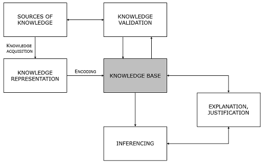
Source: Search Enterprise Artificial Intelligence
11.4 Systems Change
The idea that interventions can be designed that fundamentally reshape social or environmental systems that perpetuate injustice or negative results.
Source: “Systems Change in Social Intervention” in Stanford Social Innovation Review.
12. Conferences and Meetings
For more information on systems engineering related conferences and meetings, please go to our website.
The featured events for this edition are:
12.1 2019 Australian Systems Engineering Workshop (ASEW)
28 – 29 October 2019 – Melbourne, Australia
The Systems Engineering Society of Australia (SESA) is proud to host the Australian Systems Engineering Workshop (ASEW) in Melbourne from 28th to 29th October 2019.
If you are involved in the delivery of new capability or the provision of critical infrastructure services or even at the forefront of the Sustainability Era then the ASEW will contribute significantly to your journey. Whether you are a seasoned practitioner of Systems Engineering or have recently become introduced to the methodology these two days will add direct value to the challenges you face every day. Through various modes of workshop engagement, this event provides access to Peers and technical specialists across numerous industries to breakdown and explore present day and real world issues. As a minimum you will walk away with a deeper understanding of many of the complex or complicated engineering topics being faced by our nation but more than likely you will gain a different perspective or alternative approach that will stimulate change and promote a new way of solving YOUR current problems. This is the power of Systems Thinking within the collective experience of our national Systems Engineering cohort.
The 2018 ASEW was held in Adelaide and saw the continuation of the multi-stream approach to ensure topics and themes of relevance to all participants. This was a very successful event and saw a record number of attendees participating and actively contributing to the facilitated workshops. The industries represented included Transport, Healthcare, Telecommunications, Energy and Space. In addition to the workshops and initiatives discussed at ASEW18, SESA members participate in a number of International Working Groups (through INCOSE) which are used to catalyze the development of technical product and inform the Systems Engineering Body of Knowledge. Some of these working groups include
- Complex Systems
- System-of-Systems
- Requirements
- Project Management – Systems Engineering Integration
- Model-based Conceptual Design
- Engineering Process Standards
This year we will continue from the success of ASEW18 and leverage the 2 established and recognized SESA Working Groups within Transport and Telecommunications to further explore the progress and uptake of Systems Engineering within their respective industries. In addition to this and to ensure a program built to deliver on YOUR professional needs; If you have a problem, if no one else can help, and if you can find them, maybe you can register your interest for ASEW19.
More information here.
12.2 2019 Annual INCOSE Western States Regional Conference (WSRC)
12 – 15 September 2019 – Los Angeles, USA
The Future State of Systems Engineering, according to the INCOSE Vision 2025, will make significant strides in meeting the challenges and needs of the global environment, human and societal needs, policy and business challenges, as well as the technologies that underlie systems. Its relevance and influence will go beyond traditional aerospace and defense systems and extend into the broader realm of engineered, natural and social systems. WSRC2019 has tracks being formed to address SE Application to Healthcare and Medical Devices and SE in Large Observatories being developed to explore the farthest reaches of the universe.
WSRC2019 is for the entire western region of the United States community – not just INCOSE members and not just systems engineers. The community is connected by our shared interest in the successful advance of systems vital to our regional and global prosperity.
WSRC2019 will feature an INCOSE SE Professional Development Day (SE PDD). The SE PDD will be a virtual extension of the conference, with the featured sessions broadcast from LMU to several satellite sites on Saturday the 14th of September.
Technical program
Thursday – Friday
- Optional Workshop (2 Day: Thurs./Fri. 9 a.m. – 5 p.m.): SE Bootcamp: Taking SE to the Next Level.
Friday
- Optional Workshop continues.
- Full-Day Workshop: CSEP Examination Preparation Class, Systems Engineering Handbook V4.0 (day-one of two) 9 a.m. – 5 p.m.
- Half-Day Tutorial: Systems Engineering to the Rescue. 9 am – 12 pm
- Half-Day Tutorial: Correcting Misperceptions of Systems Engineering Practices, 1pm – 5pm.
Saturday
- Multi-track Presentations and Panel Discussion: Work force, Healthcare, Agile, MBSE, Systems Research and Analysis, Natural and Social Systems
- Systems Engineering Professional Development Day (SE-PDD) Track, with speakers from each of the tracks listed
- Regional Remote Satellite Sites Will be Available
- Full Day Workshop: CSEP Examination Preparation Class, Systems Engineering Handbook V4.0 (day-two of two) 8:45 a.m. – 5 p.m. (Second Half)
- Cocktail Hour (5pm – 6 pm) and Optional Dinner Banquet: Keynote Speaker: LtCol Kellie Brownlee, AF Space Future Ground Systems, 6 – 9 p.m.
Sunday
- Keynote Speaker: Dr. George Angeli, SE for Giant Telescope Observatories
- Multi-track presentations and Panel Discussions: Agile, MBSE, SE Perspectives, SE Case Studies
- Systems Engineering Professional Exam for INCOSE ASEP/CSEP Certification (9.45am – 12pm)
- Optional Tour (1pm – 4 pm): NASA/Northrop-Grumman Museum and James Webb Space Telescope (if accessible)
Download a list of all presentations/panels and tutorials and the presenters here: Technical Program
13. PPI and cti News
PPI is delighted to welcome Kayleigh Elliot to the PPI family! Kayleigh will assume position of Corporate Communications Manager, a role spanning a range of responsibilities including interacting with PPI course delegates, supporting PPI publications and support for business development and marketing. Kayleigh’s background is in corporate communications and management. Outside of her professional life, Kayleigh enjoys photography, art and writing. We know that Kayleigh’s positive energy and strong organizational skills will be very beneficial to the company. Welcome, Kayleigh!
13.2 Bijan Elahi Receives System Safety Award
Bijan Elahi, presenter of PPI’s Medical Device Risk Management 3 Day Course, has received another award, the 2019 Scientific Research and Development Award in System Safety, for innovations in quantitative methods for risk management, awarded by the International System Safety Society. Well done, Bijan!
Read Bijan’s bio here.
14. PPI and CTI Events
On-site systems engineering training is being delivered worldwide throughout the year. Below is an overview of public courses. For a full public training course schedule, please visit https://www.ppi-int.com/course-schedule/
Systems Engineering 5-Day Courses
Upcoming locations include:
- Bristol, United Kingdom (P006-782)
16 Sep – 20 Sep 2019
Requirements Analysis and Specification Writing 5-Day Courses
Upcoming locations include:
- Melbourne, Australia (P007-484)
14 Oct – 18 Oct 2019
Systems Engineering Management 5-Day Courses
Upcoming locations include:
- Stellenbosch, South Africa (P1135-163)
16 Sep – 20 Sep 2019
Systems Engineering Overview 3-Day Courses
Upcoming locations include:
- Chantilly, Virginia, United States of America (P884-15)
09 Dec – 11 Dec 2019
Requirements, OCD and CONOPS in Military Capability Development 5-Day Courses
Upcoming locations include:
- Pretoria, South Africa (P958-58)
21 Oct – 25 Oct 2019
Engineering Successful Infrastructure Systems (ESIS5D)
Upcoming locations include:
- Las Vegas, Nevada, United States of America (P2005-3)
02 Dec – 06 Dec 2019
Architectural Design 5-Day Course
Upcoming locations include:
- London, United Kingdom (P1768-23)
09 Nov – 13 Nov 2019
CSEP Preparation 5-Day Courses (Presented by Certification Training International, a PPI company)
Upcoming locations include:
- Utrecht, the Netherlands (C002-85)
02 Sep – 06 Sep 2019
Medical Device Risk Management 3-Day Course
Upcoming locations include:
- San Francisco, California, United States of America (P1848-4)
18 Nov – 20 Nov 2019
Other training courses available on-site only include:
- Project Risk and Opportunity Management 3-Day
- Managing Technical Projects 2-Day
- Integrated Product Teams 2-Day
- Software Engineering 5-Day
15. Upcoming PPI Participation in Professional Conferences
PPI will be participating in the following upcoming events. We support the events that we are sponsoring and look forward to meeting old friends and making new friends at the events at which we will be exhibiting.
Asia Oceania Systems Engineering Conference 2019
(Exhibiting)
Date: 17 – 18 October, 2019
Location: Bangalore, India
INCOSE UK Annual Systems Engineering Conference
(Exhibiting)
Date: 19 – 20 November, 2019
Location: Leeds, England, UK
The INCOSE International Symposium 2020
(Exhibiting)
Date: 18 – 23 July, 2020
Location: Cape Town, South Africa
Kind regards from the PPI SyEN team:
Robert Halligan, Editor-in-Chief, email: rhalligan@ppi-int.com
Ralph Young, Editor, email: ryoung@ppi-int.com
René King, Managing Editor, email: rking@ppi-int.com
Project Performance International
2 Parkgate Drive, Ringwood, Vic 3134 Australia
Tel: +61 3 9876 7345
Fax: +61 3 9876 2664
Tel Brasil: +55 12 9 9780 3490
Tel UK: +44 20 3608 6754
Tel USA: +1 888 772 5174
Tel China: +86 188 5117 2867
Web: www.ppi-int.com
Email: contact@ppi-int.com
Copyright 2012-2019 Project Performance (Australia) Pty Ltd, trading as
Project Performance International
Tell us what you think of PPI SyEN. Email us at syen@ppi-int.info.
- Presentation by Dr. Michael Ryschkewitsch and Mr. Stephen Kapurch, NASA Office of Chief Engineer, at the Conference on Systems Engineering Research (CSER), April 15, 2011. ↑
- From the SYST 505 Course by Dr. Peggy Brouse, George Mason University. ↑
- INCOSE Charter for Future of Systems Engineering, FuSE Charter V1.2, December 3, 2018. ↑
- Owner Shortell, FuSE (Future of Systems Engineering) Town Hall. INCOSE 2019 International Symposium, Torrance, CA, US, 28 January 2019. ↑
- See www.lifecyclemodeling.org for more information concerning LML and the LML Steering Committee. ↑
- See the May 2019 issue of the Project Performance International Systems Engineering Newsletter (PPI SyEN) for an article by Dr. Vaneman entitled “Model-based Systems Engineering De-Mystified” available at https://www.ppi-int.com/ppisyen77/. ↑
- See www.lifecyclemodeling.org. ↑
- Essential LML: Lifecycle Modeling Language: a Thinking Tool for Capturing, Connecting and Communicating Complex Systems, Warren Vaneman, Ph.D., et. al., SPEC Innovations, 2018. ↑
- Concordance is defined by Dr. Vaneman as “the ability to represent a single entity such that data in one view, or level of abstraction, matches the data in another view, or level of abstraction, when talking about the exact same thing.” From “Organizational Considerations for Effective Model-Based Systems Engineering Implementation,” presented at the 21st Annual NDIA Systems Engineering Conference, October 22-25, 2018. ↑
- Note that although SysML does not have a defined ontology, many of the common words used, such as Activity and Actor, can be easily related to LML classes. ↑
- “Practical Lessons Learned from the Application of Model-Based System Engineering (MBSE) to Space Project Design Reviews,” by Dr. Jerry Jon Sellers, presented to the NDIA Modeling and Simulation Committee, February 2014. ↑
- Systems thinking is a way of thinking about, and a language for describing and understanding, the forces and inter-relationships that shape the behavior of systems. This discipline helps us to see how to change systems more effectively, and to act more in tune with the natural processes of the natural and economic world. It is the discipline that integrates disciplines. Peter Senge, The Fifth Discipline (New York: Doubleday, 1990). ↑
- In mathematics, a duality, generally speaking, translates concepts, theorems or mathematical structures into other concepts, theorems or structures, in a one-to-one fashion, often (but not always) by means of an involution operation: if the dual of A is B, then the dual of B is A. Such involutions sometimes have fixed points, so that the dual of A is A itself. Wikipedia. ↑