In This Edition
1. Quotations to Open On
2. Feature Articles
2.1 Equivalences and Differences between Arcadia/Capella and SysML by Stéphane Bonnet and Stéphane Lacrampe
2.2 It’s a Long Way to the Top if You Wanna Rock and Roll, or do Systems Engineering by Jon Holladay
3. Additional Articles
3.1 Three Ways to Ensure the Internet’s Future is Creative, Collaborative, and Fair by Claudio Cocorocchia
3.2 Integrating Program Management and Systems Engineering by Ralph Young
4. Systems Engineering News
4.1 Asynchronous/Concurrent Agile Systems Engineering Life Cycle Model Framework Released by INCOSE
4.2 Space and Naval Warfare Systems Center (SSC) Atlantic USA Pilot Program Promotes Increased Systems Engineering Discipline
4.3 INCOSE Introduces Purchasing Power Parity (PPP) Discounted Fees Effective January 2019
4.4 INCOSE 2018 Election Results
4.5 INCOSE Call for Fellows Nominations
5. Featured Organizations
5.1 World Economic Forum: International Organization for Public-Private Cooperation
5.2 Infrastructure and Projects Authority, UK
6. News on Software Tools Supporting Systems Engineering
6.1 NPS-Developed Software Detects System Design Errors Early
7. Systems Engineering Publications
7.1 Integrating SysML and Agent-Based Modeling for Rapid Architecture Evaluation
7.2 Information Technology Infrastructure Library
7.3 Continuous Testing for Continuous Delivery: What Does it Mean in Practice?
7.4 Blue Ocean Shift: Beyond Competing
7.5 Leading Change
7.6 How Do We Fix Systems Engineering?
8. Education and Academia
8.1 Naval Postgraduate School Monterey, California USA
8.2 Cornell Engineering USA to offer Systems Ph.D. Program Focusing on Logistics
9. Some Systems Engineering-Relevant Websites
10. Standards and Guides
10.1 Systems Engineering International Standards and Support Tools for Very Small Enterprises
11. Some Definitions to Close On
11.1 Very Small Entity
11.2 Systems Engineering Leading Indicators
12. Conferences and Meetings
13. PPI and CTI News
14. PPI and CTI Events
15. PPI Upcoming Participation in Professional Conferences
1. Quotations to Open On
“State is being, mode is doing.”
Robert John Halligan
“A great systems engineer completely understands and applies
the art of leadership and has the experience and scar tissue from
trying to earn the badge of leader from his or her team.”
Harold Bell, NASA Headquarters
USA’s National Aeronautical Space Administration
“The more complex the system, the more vulnerable the human element becomes[1].”
Dr. Beth Whitehead
2. Feature Articles
2.1 Equivalences and Differences between Arcadia/Capella and SysML
by
Stéphane Bonnet
Email: stephane.bonnet@thalesgroup.com
and
Stéphane Lacrampe
Email: stephane.lacrampe@obeosoft.com
Thales, Obeo
Abstract
Arcadia is an engineering method for MBSE (Model-Based Systems Engineering). Capella is an open-source tool that implements the Arcadia method.
Among the standards from which Arcadia and Capella arise, the SysML language is prominent. This article explains why Arcadia/Capella is to some extent a “SysML-like” solution to design the architecture of complex systems using models, by presenting the main diagrams and concepts equivalences and the three main differences. It also provides rationales for these.
Introduction
Designing complex and critical systems requires a level of rigor in engineering practices that only formalized and tool-supported modeling approaches can provide.
The Arcadia/Capella solution embeds methodological guidance that constitutes one of its most significant originalities and success factors. By lowering the learning curve for systems engineers and by being open-source, Capella is an enabler for large-scale Model-based Systems Engineering (MBSE) adoption.
Primarily inspired from several industry standards, Arcadia/Capella simultaneously form an enrichment and a simplification of SysML: a significant proportion of the core concepts of the Arcadia method can be mapped directly onto the SysML standard, and most SysML diagrams have “twins” in Capella.
This article first discusses the extent to which Arcadia/Capella can be considered as a “SysML-like” solution, by providing a high-level positioning and by illustrating diagrams and concepts similarities. It then elaborates on the main differences between SysML and Arcadia/Capella and provides rationales for these. Finally, it provides a quick tooling perspective.
Objectives of this article
SysML is the most widely used language for systems modeling. Capella is not strictly relying on SysML, so the question of positioning Capella with regards to SysML is often raised. This article provides elements of answers. It does not constitute a deep dive into the specifics of SysML language or Arcadia/Capella but it establishes a mapping of the main diagrams and concepts.
This article primarily targets people considering using Capella but having second thoughts because “it is not SysML”, or people who do not have extensive knowledge of SysML and Arcadia/Capella. SysML experts who may be curious or are questioning the Arcadia/Capella approach may also find food for thought.
Disclaimer
No one should take offense concerning the content of this article. We do not pretend to be absolute SysML experts, and as such we may write things about SysML that are sometimes incomplete or not quite exact. In that case, we will be happy to engage in discussions and correct things that we may have misunderstood. The fact that Arcadia and Capella do not rely on SysML is a choice that was made a decade ago by the Arcadia creators, and we are trying to explain here the rationale behind this choice.
The scope of Arcadia Capella should always be kept in mind when reading this article. While the intent of the SysML language is to cover a broad range of applications, Arcadia/Capella is mainly targeted to architectural design. Moreover, the exercise we are doing here is actually comparing apples and oranges: On one side we have SysML, a language, and on the other side, we have Arcadia and Capella which are a method and a tool. Comparing the two is a challenging exercise that may not make complete sense, but since we get the question very often, it needs to be addressed.
Finally, while we are convinced that Arcadia and Capella are providing very efficient means to improve systems engineering practices, we cannot pretend to be fully impartial. We also believe that there is no silver bullet tool or method and that there are many other aspects to consider than just the language when implementing MBSE.
Arcadia quick introduction
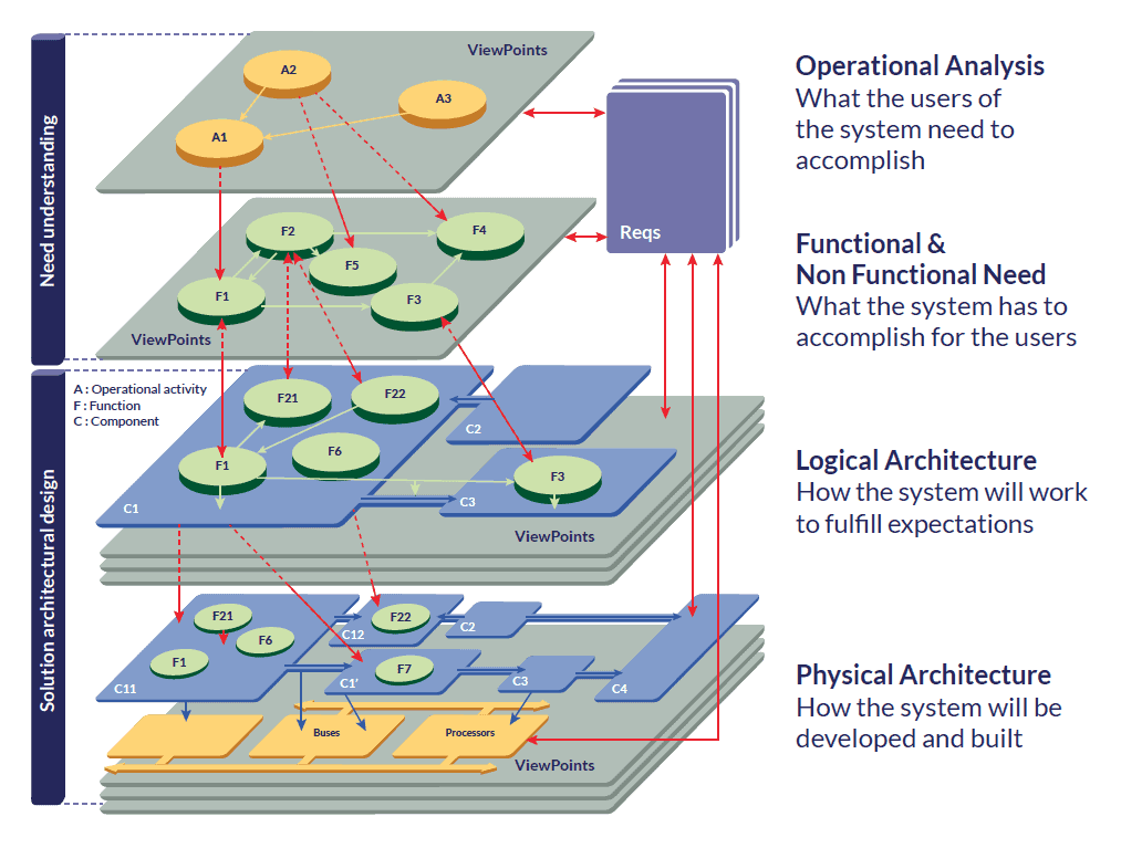
Figure 1: Arcadia engineering layers
Arcadia is an engineering method for MBSE. It tries to enforce a clear separation between the need modeling and the solution modeling. Therefore it is intended to provide guidance to systems engineers to design the architecture of their systems.
The primary goals of Arcadia are (i) to provide the means to build architectural designs, (ii) to evaluate architecture early, and (iii) to prepare and secure the sub-contracting with the downstream engineering teams. Arcadia is mainly about performing functional analyses, identifying sub-systems, identifying the interfaces between sub-systems, and justifying them using functional content.
The core concepts and engineering perspectives used in Arcadia are simple and common. A dedicated datasheet presents them and a previous newsletter PPI SyEN 054 introduced Arcadia.
High-level positioning
The table below provides a general overview of the positioning between SysML and Arcadia/Capella:
| SysML | Arcadia/Capella | |
| Positioning | SysML is a standard and a general-purpose modeling language for modeling systems. SysML provides rich and advanced expression means covering a vast spectrum of applications, spanning from high-level architecture modeling to detailed design at the frontier of simulation. | Inspired by SysML concepts, the Arcadia/ Capella solution focuses on the design of systems architectures. For the sake of a softer learning curve and because of the precise scope addressed by Arcadia/Capella, the expression means are sometimes reduced compared to SysML. The ultimate goal of Arcadia/Capella is to have systems engineers embrace the cultural change of MBSE rather than having modeling “experts” owning the model on behalf of systems engineers. Therefore, Arcadia/Capella are strongly driven by the current practices and concerns of system engineering practitioners. |
| Method | SysML is not associated with a particular method even though several engineering methods can be implemented using SysML. As such, SysML provides a vocabulary, but it does not specify when to use one concept or another, how to organize models, etc. | The Arcadia method enforces an approach structured on different engineering perspectives establishing a clear separation between system context and need modeling (operational need analysis and system need analysis) and solution modeling (logical and physical architectures), complying with the IEEE 1220 standard and covering parts of ISO/IEC/IEEE 15288. |
| Language | Technically, the SysML language itself is an extension of the Unified Modeling Language (UML). Both UML and SysML are general-purpose languages targeting broad spectrums of engineering domains and rely on software-originated engineering paradigms using types, inheritance, etc. | The Arcadia concepts are mostly similar to the UML/SysML standard (about 75%) and the NATO Architecture Framework (NAF) standard (5%). Interoperability with SysML tools is possible using ad-hoc imports/exports. Because of the focus on architectural design, some of the SysML concepts have been simplified or specialized to better match the concepts system engineering practitioners already use in their documents and assets. This is the case with the concepts related to functional analysis for instance. |
Diagram equivalences and similarities
This section describes the similarities and equivalences between SysML and Capella diagrams using a simple camera model that was first used by M. Sanford Friedenthal in the SysML V2 Working Group in order to illustrate requirements for the integration between behavior and structure modeling. This simple model has been adapted and used to provide the same Working Group with feedback on how this integration is performed in Capella.
Block Definition Diagram (BDD)
The Block Definition Diagram in SysML captures the definition of blocks in terms of properties, operations, and relationships such as a system hierarchy or a system classification tree. It defines features of blocks and relationships between blocks such as associations, generalizations, and dependencies, as illustrated in Figure 2. It is actually a redefinition of the UML Class diagram.
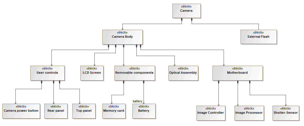
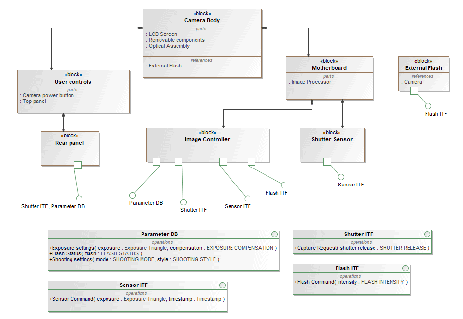
Figure 2: SysML BDD Diagrams
In Capella, blocks are called “components”, and two different diagrams relate to SysML BDD diagrams as illustrated in Figure 3:
- Component Breakdown Diagrams show the component hierarchy through a graphical tree.
- Component Interface Diagrams show composition relationships between components through graphical containment and relationships between components and interfaces through ports. Component properties are not displayed graphically.
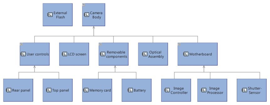
Figure 3: Capella Component Breakdown and Component Interfaces Diagrams |
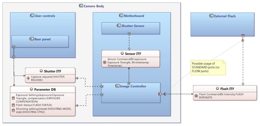
Internal Block Diagram (IBD)
In SysML, the Internal Block Diagram captures the internal structure of a block in terms of properties and connectors between properties, as illustrated in Figure 4.
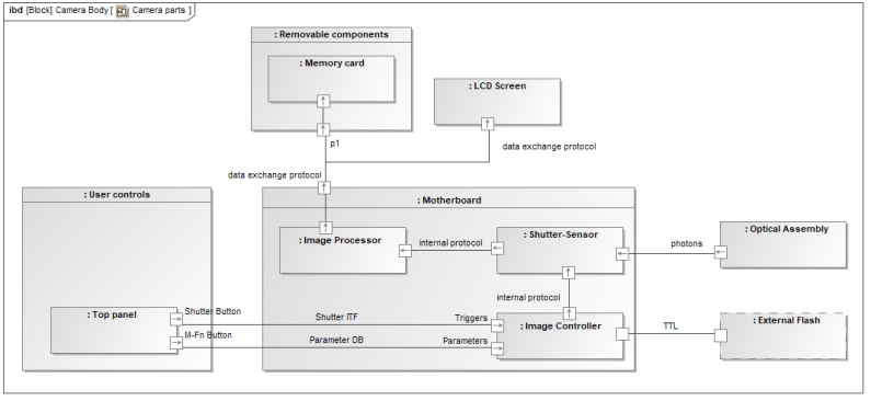
Figure 4: SysML IBD Diagram
The corresponding diagram in Capella is called Arcadia Architecture Diagram (see Figure 5). It describes the assembly of components in terms of internal breakdown and connections (see the dedicated section “The three main differences” to understand how the concepts of parts, blocks, and cardinalities are managed in Capella).
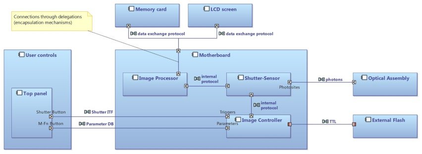
Figure 5: Capella Architecture Diagram
Activity Diagram
In SysML, the Activity Diagram is a behavior diagram representing the flow of control and objects between actions describing activities (see Figure 6).
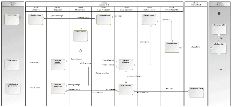
Figure 6: SysML Activity Diagram
Capella functions naturally map to SysML activities/actions (see Figure 7). However, while SysML Activity Diagrams are primarily intended to specify the control flows between activities, Capella Dataflows Diagrams only present the dependencies between functions with absolutely no semantics of control. The rationale for this choice is explained in this dedicated paper.
Allocating functions to components in Capella is similar to allocating actions to partitions representing blocks in SysML. Capella Architecture Diagrams resemble a mapping of SysML Activity Diagrams onto Internal Block Diagrams. The following diagram on the right is a Capella Architecture Diagram voluntarily made similar to a SysML Activity Diagram where actions are displayed in vertical partitions. Mapping SysML Activity Diagrams to Capella is not as straightforward as it looks and the dedicated section “The three main differences” explains this point more extensively by detailing how Capella handles functional analyses.
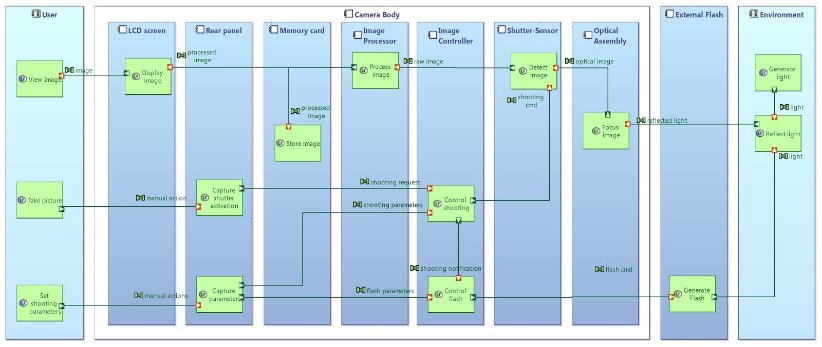
Figure 7: Capella Architecture Diagram
Sequence Diagram
In SysML, Sequence Diagrams describe the interaction information with a focus on the time sequence. The diagram we included below (see Figure 8) represents the sending and receiving of messages between the interacting entities called lifelines, where the vertical axis represents time. The sequence diagrams can represent highly complex interactions with advanced constructs to represent various types of control logic, reference interactions on other sequence diagrams, and decomposition of lifelines into their constituent parts.
In Capella, the underlying constructs of Sequence Diagrams are strictly mapped onto SysML ones. The main difference resides in the variety of elements that can be referenced consistently by lifelines and sequence messages. The next three diagrams illustrate different usages:
- Figure 9 where lifelines represent components (blocks in SysML) and sequence messages represent dependencies existing between the functions (actions/activities in SysML) respectively allocated to source and target components.
- Figure 10 where lifelines represent functions (actions/activities in SysML) and sequence messages represent dataflows between these functions.
- Figure 11 where lifelines represent components or data (blocks in SysML) and sequence messages represent operations belonging to the interfaces provided/required by the source and target components.
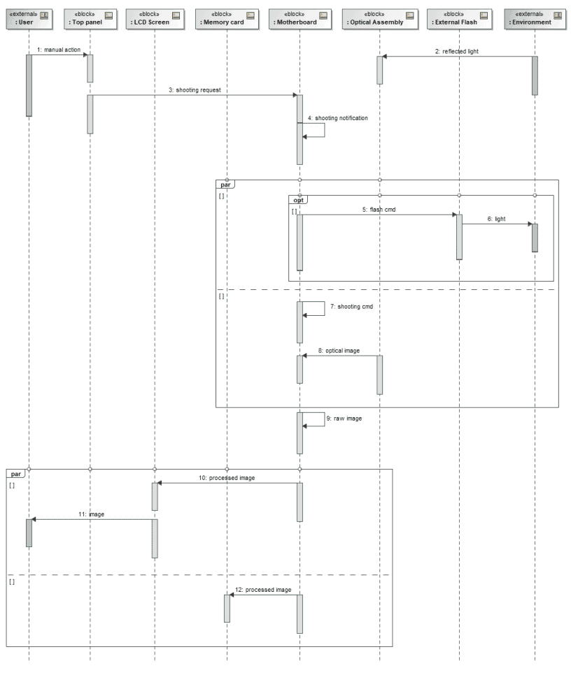
Figure 8: SysML Sequence Diagram
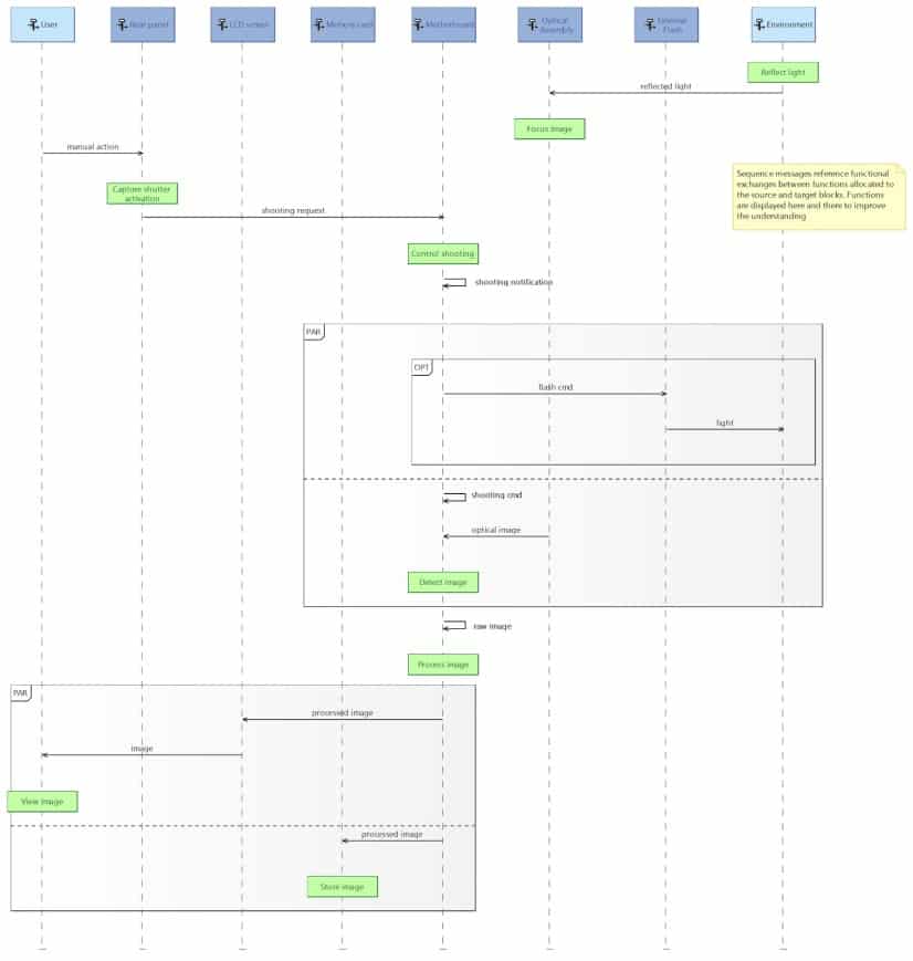
Figure 9: Capella Sequence Diagram
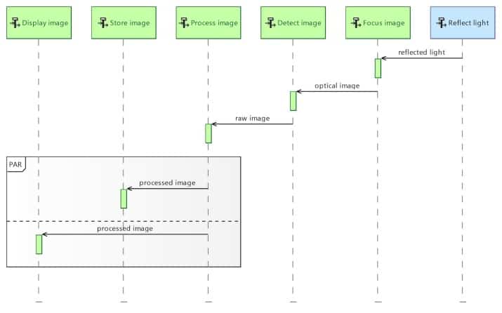
Figure 10: Capella Sequence Diagram
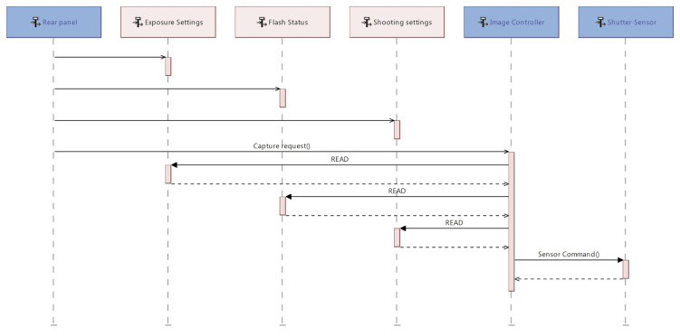
Figure 11: Capella Sequence Diagram
State Machine Diagram
In SysML, the State Machine Diagram (see Figure 12) is a behavior diagram describing the state transitions and actions that a system or its parts perform in response to events. It is used for representing behavior as the state history of an object in terms of its transitions and states.
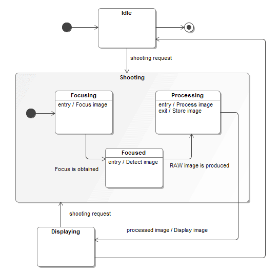
Figure 12: SysML State Machine Diagram
In Capella, the Modes and States Machines are almost similar to SysML ones. The constructs are the same, but Capella adds a bit of semantics: differentiation between modes and states, articulation with functional analysis, and interfaces. This makes it easier for system engineers or end-users to understand and manipulate this kind of diagram. This simplification of SysML Modes and States also means that Capella is more limited in its expressiveness, but it fits the primary objective of Arcadia which is to design architectures, and not necessarily to perform low-level modeling of systems components where a richer expressiveness as provided by SysML can definitely be necessary.
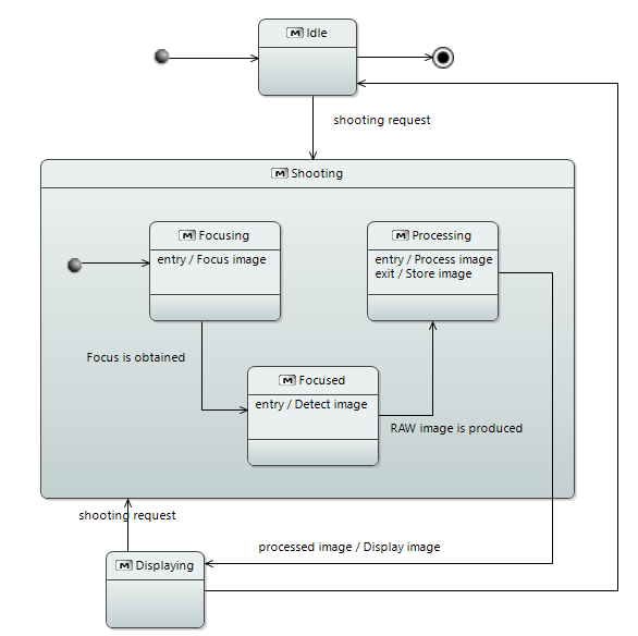
Figure 13: Capella Modes and States Diagram
Use Case Diagram
In SysML, the Use Case Diagram (see Figure 14) is a method for describing the usages of a system. It represents a high-level description of functionalities that are achieved through interaction between a system (subject) and its actors (environment) to achieve a goal.
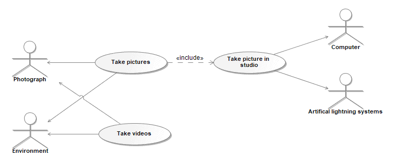
Figure 14: SysML Use Case Diagram
In Capella, capabilities are equivalent to SysML use cases, and Capabilities Diagram (see Figure 15) mostly resembles the SysML Use Case Diagram. Capabilities are intensively used in Capella to organize the functional analysis: the involvement of stakeholders in a given capability is enriched by a specification of the stakeholder functions performed in the context of this capability.
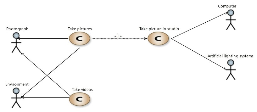
Figure 15: Capella Capabilities Diagram
Requirement Diagram
SysML includes a graphical construct to represent text-based requirements and relate them to other model elements. The Requirements Diagram (see Figure 16) captures requirements hierarchies and requirements derivation, and the satisfy and verify relationships allow a modeler to relate a requirement to a model element that satisfies or verifies the requirements. The requirement diagram provides a bridge between the typical requirements management tools and the system models.
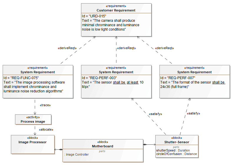
Figure 16: SysML Requirements Diagram
In Capella, there is no dedicated Requirements Diagram, but users can display all textual requirements in any diagram (see Figure 17), as for relationships between requirements and model elements and relationships between requirements. To achieve that, we use the Capella Requirements add-on that can be downloaded from here.
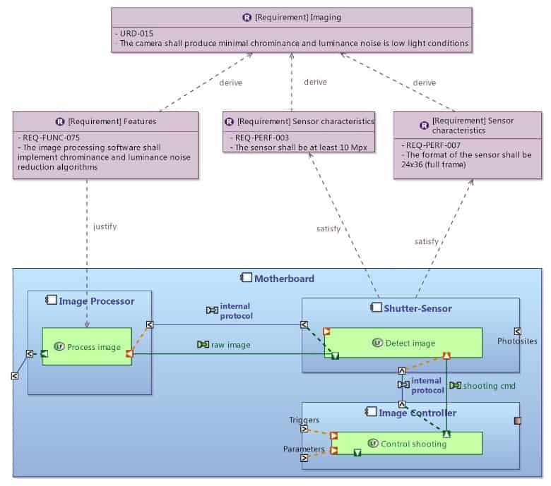
Figure 17: Visualizing Requirements in Capella Diagrams
Class Diagram
The UML Class Diagram (see Figure 18) does not belong to the official subset of UML diagrams available in SysML (it is replaced by the Block Definition Diagram, itself based on the UML Class Diagram, with restrictions and extensions). However, it is presented here, as it is a classic addition to SysML diagrams.
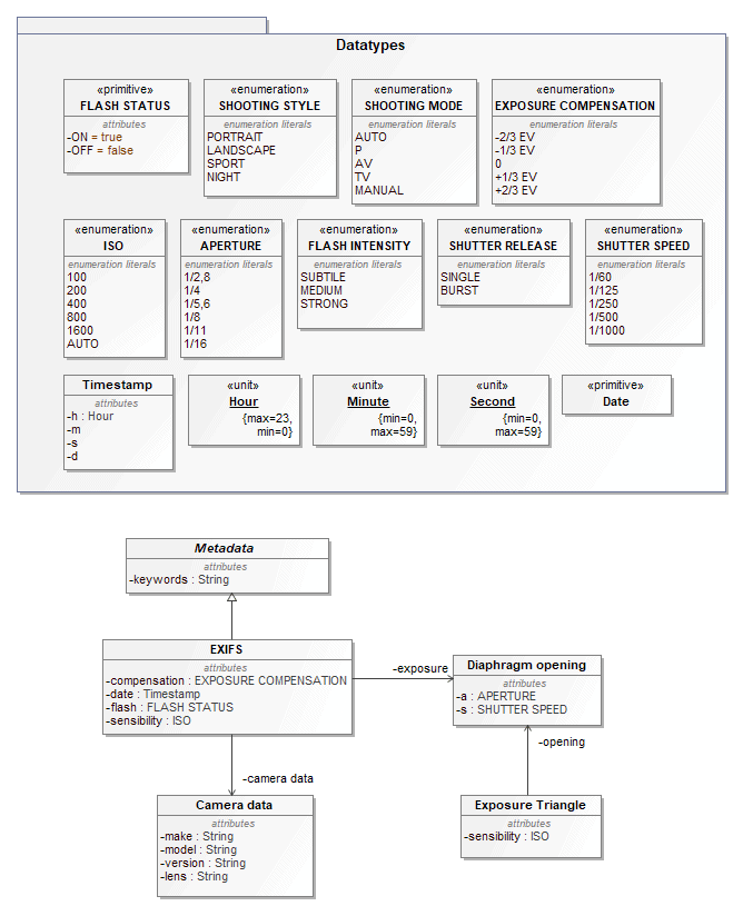
Figure 18 : UML Class Diagram
In Capella, Class Diagrams (see Figure 19) are fully aligned on UML Class Diagrams while adding a certain amount of construction rules: prohibiting dependency cycles for example or enforcing visualization choices according to the properties of elements.
Parametric Diagram
In SysML, Parametric Diagrams (see Figure 20) are a restricted form of Internal Block Diagram that shows only the use of constraint blocks along with the properties they constrain within a context. Parametric Diagrams are used to support engineering analysis, such as performance or mass properties analysis
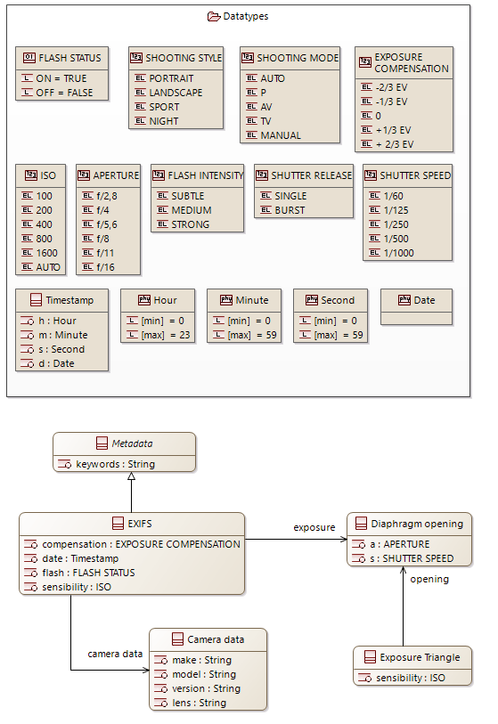
Figure 19: Capella Class Diagram
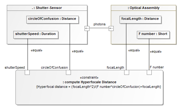
Figure 20: SysML Parametric Diagram
In Capella, while most of the underlying concepts are present (constraints, opaque expressions with assisted editing, parse-able expressions, properties on elements, physical dimensions, etc.), no diagram is dedicated to their graphical display (see Figure 21).
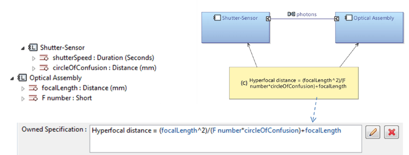
Figure 21: Constraints and Expressions with Capella
Capella users typically use dedicated viewpoints (language and analyses extensions with additional graphical layers on top of existing diagrams) to evaluate their architecture against non-functional constraints. They rarely use the architecture models for simulation purposes. Should the end-user request them, parametric diagrams could be a simple addition to Capella.
The three main differences
Functional Analysis
Functional analysis is a classical technique broadly used by systems engineers. Arcadia/Capella provide methodological guidance and engineering helpers to support this technique that has been mostly left out of SysML V1.
The mapping of Capella functions to SysML activity is the most natural one from a semantic viewpoint. Capella functions are verbs specifying the actions expected from the components they are allocated to. This section describes the structural differences between SysML activities/actions and Capella functions.
In SysML, the articulation between several Activity Diagrams (see Figure 22) relies on two major concepts: activities are described by different kinds of actions including some that can reference other activities, and the parameters of a given activity are connected (delegated) to the output or input pins of the actions describing it. This strong encapsulation/delegation mechanism favors the reuse of activity definitions in multiple contexts but imposes constraints on what a single diagram can represent and makes bottom-up workflows more challenging to implement as illustrated below.
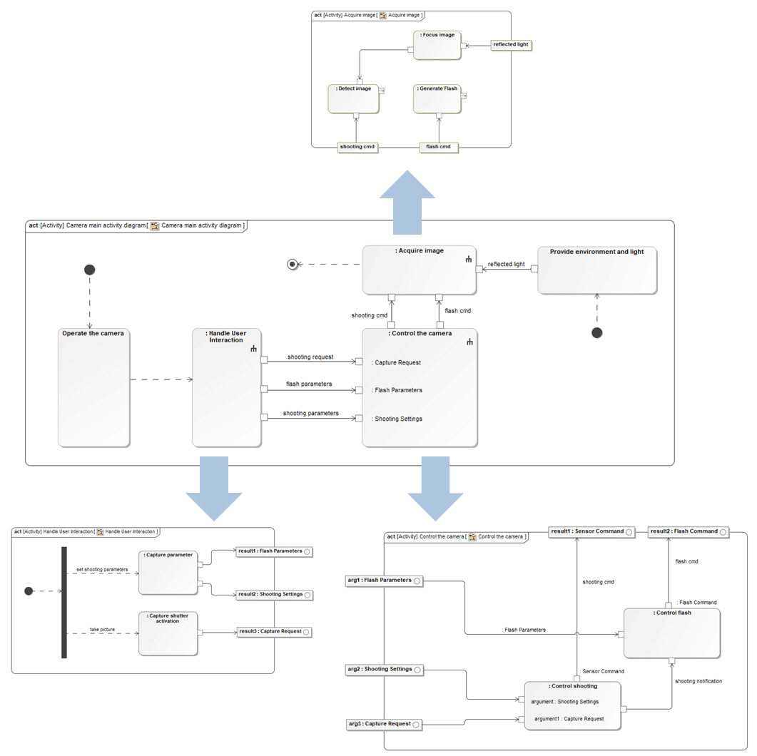
Figure 22: Articulation between Activity Diagrams in SysML
In Capella, the philosophy differs significantly: there are three major differences between SysML Activity Diagrams and Capella dataflows:
- There is no control flow in Capella Dataflow Diagrams, meaning that there is no semantics of execution and there are no control nodes such as Join, Fork, etc. The detailed rationale for the absence of control flows in Capella dataflow is explained in this dedicated paper.
- The relationship between a function and its sub functions is a direct containment
- There is no delegation mechanism between functions ports at each level of decomposition in Capella. The rationale is detailed hereunder.
In a hierarchy of Capella functions, non-leaf functions are only “grouping” elements. This means:
- Non-leaf functions are not supposed to have ports nor functional dependencies.
- Non-leaf functions are not supposed to be allocated to components.
- A leaf function can be connected freely to any other leaf function.
- When a non-leaf function has ports, the design is considered non-finalized. The remaining ports are supposed to be (dragged and) moved towards a leaf function.
- Low-levels dependencies between leaf functions are automatically displayed when intermediate/parent/non-leaf functions are displayed on a diagram.
This strong modeling choice aims at:
- Managing the complexity of functional trees by relieving engineers from the tedious task of maintaining the consistency of dependencies at all levels of decomposition, which can become a real burden when reaching several hundreds of functions.
- Allowing the immediate production of simplified views for the functional analysis, at no cost.
- Enabling a natural combination between top-down and bottom-up workflows, which is essential to support day to day work of systems engineers.
Capella leverages this language choice to provide several kinds of simplified views of the system architecture. The next diagrams (see Figure 23) hereunder illustrate these capabilities; first let’s take this Dataflow diagram:
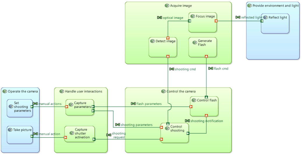
Figure 23: Capella Dataflow Diagram
The following diagram (see Figure 24), for example, is automatically computed. Ports are displayed on non-leaf functions but still belong to children functions.
Similarly, graphical simplifications of Architecture Diagrams can be computed by automatically performing grouping at component and function levels, as illustrated in the next set of two diagrams (see Figure 25 and 26).
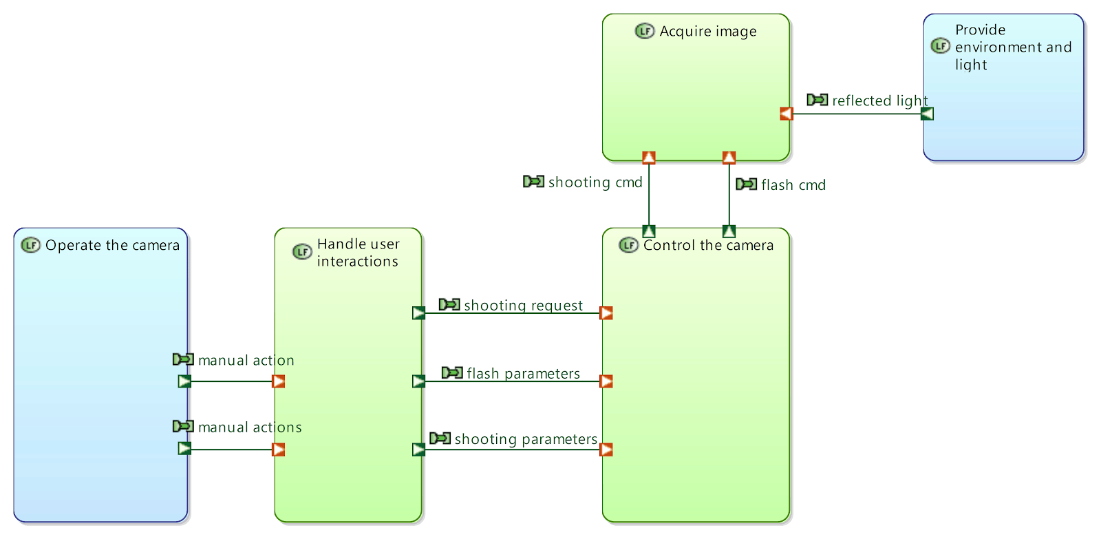
Figure 24: Automatically computed diagram with Capella
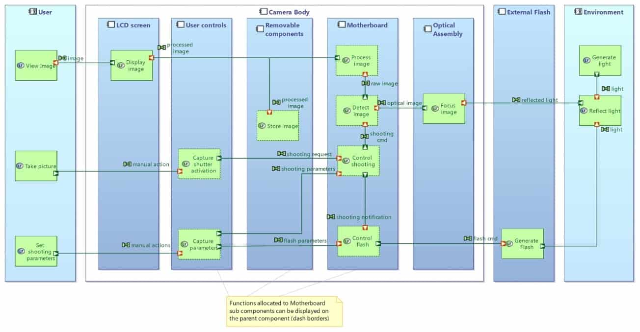
Figure 25: Capella Architecture Diagram
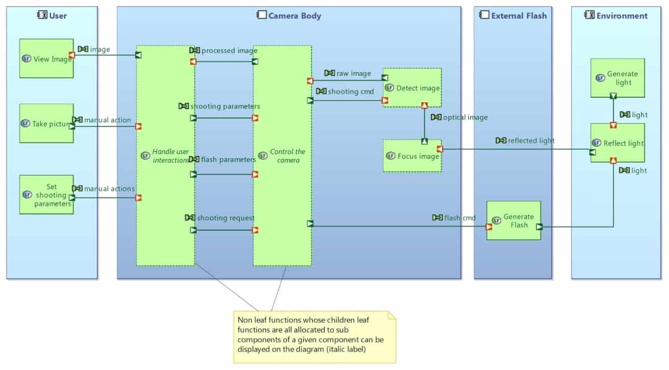
Figure 26: Automatically computed diagram with Capella
Functions/Components/Interfaces integration
The most important objective of the Arcadia method is to secure the architectural design activity through identification and justification of the interfaces. This goal is achieved by providing a global approach to conduct functional, structural, and interface modeling in parallel (see Figure 27):
- Identification of the functional expectations of the subsystems (allocation of functions to components).
- Identification of the functional dependencies between the subsystems (specification of the exchanges between functions ideally with a structural description of the exchanged items).
- Allocation of functional dependencies to assembly relationships between subsystems (allocation of functional ports to component ports, allocation of functional exchanges to component exchanges, etc.).
- Specification of the interfaces provided and required through component ports (with a possible automated deduction based on all the specification mentioned above).
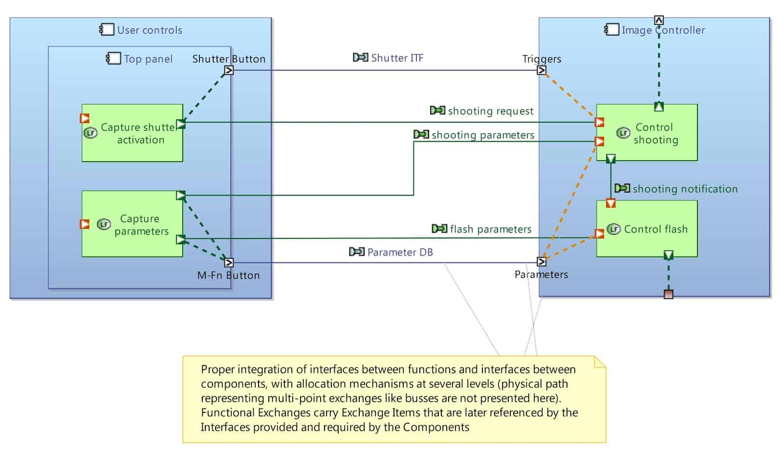
Figure 27: Integration of Interface/Component/Function with Capella
Instead of showing the actual element name, the label of functional dependencies can show references towards the exchanged items (see Figure 28).
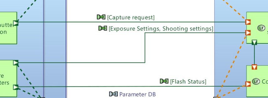
Figure 28: Exchanged items label
The following diagram details the content of the interfaces between the components deduced from the functional analysis and multiple allocations.
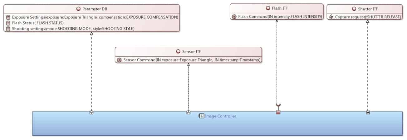
Figure 29: Interface definition with Capella
This integration of the functions/components/interfaces triptych is not straightforward to implement and enforce in SysML v1. This global approach promoted in Capella also comes with a set of assistance tooling enforcing the model correctness regarding this integration and providing automation means. This is key in architectural design. The topic of better integration between structure and behavior is currently being addressed within the SysML v2 Submission Team.
Management of “instances” or “Definitions and Usages”
The SysML Internal Block Diagram is dedicated to model the internal structure of a block. SysML relies on a generic block/part paradigm: in an Internal Block Diagram, a block can be decomposed into parts (usages) which are themselves typed by other blocks (definitions). A bicycle “block” has two parts “front wheel” and “rear wheel” which are both typed by the block “wheel”. The “wheel” definition is captured in one dedicated block, and the same definition can be reused many times in the system through the part concept.
It is possible in Capella to use the same block/part paradigm as in SysML. The following diagrams (See Figures 30) show how the memory card compartment of the camera can have two slots. There is only one “Memory Card” component but referenced twice. The component breakdown diagram shows the unicity of the “Memory Card” component.
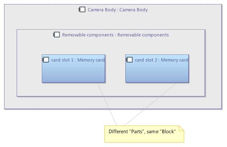

Figure 30: using the block/part paradigm with Capella
However, Capella is configured by default for instance-driven modeling. Feedback showed that systems engineers are not necessarily comfortable with the workflow of creating definition elements first (“blocks” or “components”) and then referencing them from specific usage elements (“parts”).
Besides, architectural design in Capella also consists in performing non-functional analyses where it is critical to be able to distinguish the different occurrences of each element and to be able to give them different properties or values. For example, safety analyses typically require distinguishing between the executions of an identical function in two distinct components.
This means components and functions in Capella are by default considered as instances or usages (see Figure 31).
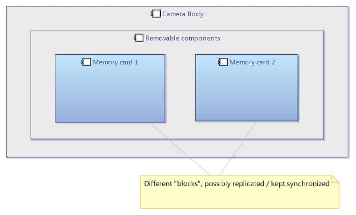
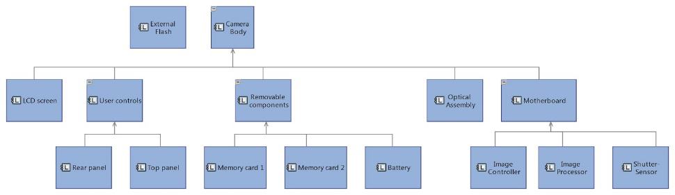
Figure 31: Instance modeling with Capella
To support this approach, Capella provides automated mechanisms allowing the replication and synchronization of model elements (REC/RPL, for Records and Replica). This topic is known as “usage-based modeling” in the SysML v2 Submission Team, the goal being to have a language able to support multiple creation workflows efficiently.
A quick tooling perspective
Given the previously described similarities but also differences between SysML and Arcadia/Capella, one might wonder why Capella is not just a SysML profile. There are several reasons:
- About thirteen years ago and for three or four years, the Capella team tried hard to implement a Capella profile, not with SysML but with UML at that time, including extensive tooling support for this profile. They struggled quite a bit because they were not able to sufficiently hide the underlying concepts which did not need to be exposed to the systems engineers. This led to several problems, including broken/invalid models when users exploited concepts outside the method bonds.
- When implementing sophisticated tooling like the Functional Analysis and all the simplifications mechanism presented in the second part of this article, the development team found limitations in the underlying diagrams that they could use in UML or SysML tools.
- Another strong reason is that even if the tooling itself could have hidden some of the complexity of the underlying language, it would not have been fully satisfying. The end-users need to exploit their models, they need to develop viewpoints and validation rules, they need to perform queries using the concepts they are familiar with. For instance, a Capella user can query a model by asking something like “Give me all Logical Components and their Functions”. If a UML/SysML has been used, the same query would be “Give me all the Blocks with LC stereotype and their Actions with LF stereotypes”. Working with profiles today means that the underlying complexity cannot be hidden when end-users want to exploit the model. This means end-users would have to learn both the language (SysML) and how the language is mapped to the method (Capella profile).
We support (and are slightly involved in) the SysML v2 Submission Team. We feel that this is an exciting initiative and our goal for Capella is to seek some kind of alignment with SysML v2 core concepts and to ease interoperability. More importantly, we think that the whole MBSE and systems engineering community would benefit a lot from the emergence of a standard API so that interoperability between tools go beyond import/export capabilities.
List of Acronyms Used in this Paper
Acronym Explanation
ARCADIA Architecture and design integrated approach
CAPELLA Open-source MBSE tool implementing the ARCADIA method
DSL Domain-specific language
MBSE Model-based systems engineering
SysML Systems modelling language
UML Unified modelling language
References
Joe Silmon, Jean-Luc Voirin, and Stéphane Bonnet. Coupling Methodology and Tooling for Systems Modelling: ARCADIA and Capella at Thales. PPI SyEN 54, June 2017.
Jean-Luc Voirin, Stéphane Bonnet, Daniel Exertier, Véronique Normand, Simplifying (and enriching) SysML to perform functional analysis and model instances, INCOSE International Symposium, 2016.
Jean-Luc Voirin, Stéphane Bonnet, Daniel Exertier, Véronique Normand, Not (strictly) relying on SysML for MBSE: language, tooling and development perspectives, Annual IEEE Systems Conference, 2016.
IEEE 1220-2005 – Standard for Application and Management of the Systems Engineering Process.
ISO/IEC/IEEE 15288:2015 – Systems and software engineering — System life cycle processes.
Stéphane Bonnet, Webinar “How Capella is different”, Thales S.A., September 2017.
Stéphane Bonnet, Webinar “Equivalences and differences between SysML and Arcadia/Capella”, Thales S.A., Obeo S.A.S, June 2018.
Capella web site: https://polarsys.org/capella
Arcadia datasheet: https://polarsys.org/capella/resources/Datasheet_Arcadia.pdf
Capella Requirements add-on: https://polarsys.org/capella/download.html
Arcadia public forum: https://polarsys.org/forums/index.php/f/12/
Capella public forum: https://polarsys.org/forums/index.php/f/13/
2.2 It’s a Long Way to the Top if You Wanna Rock and Roll,
or do Systems Engineering
An Introduction to the United States of America’s National Aeronautical Space Administration’s Systems Engineering Technical Discipline Team and Recent Accomplishments

National Aeronautics and Space Administration 60th Anniversary
Image Credit: NASA
by
Email: Jon.Holladay@nasa.gov
NASA Systems Engineering Technical Discipline Team Lead and Technical Fellow
Abstract
In the near future, NASA will put the Systems Engineering (SE) discipline to the test by fielding numerous complex missions, including the capability to transport humans beyond Low Earth Orbit and enabling two U.S. commercial providers to transport humans to the International Space Station. Establishment of a human outpost in the lunar vicinity will serve as a proving ground for Mars access and deployment of the James Webb Space Telescope. This paper provides an overview of how NASA implements the systems engineering capability required to accomplish these inspiring missions.
Introduction
One can find numerous articles on systems engineering; one of my favorites is titled, “The Art and Science of Systems Engineering”. Backed by 390 years of experience from NASA Systems Engineers, it states “We can think of a symphony as a system. The musicians apply the science of music: they follow the process of translating notes on a page to play their instruments. But an orchestra conductor, a maestro, must lead them to connect the process of playing to the art of creating great music. Maestros do a lot more than just keep time! The systems engineer is akin to a maestro, who knows what the music should sound like (the look and function of a design) and has the skills to lead a team in achieving the desired sound (meeting the system requirements).”
Since NASA’s inception in 1958, systems engineers have been on point, orchestrating a portfolio of missions almost as diverse as the genres of music. Highlights include the development and operation of systems that have visited every planet in the solar system and beyond, allowed men to walk on the surface of the moon, and now provide a continuous human presence in space. Furthermore, a multitude of spacecraft have been deployed looking outward on our solar system and universe as well as looking downward on Earth. Numerous improvements to our aeronautics community have also been supported from technology advancements for flight to the National Air Space infrastructure – see NASA: 60 Years and Counting. NASA’s current vision, as stated in the 2018 Strategic Plan, is “to discover and expand knowledge for the benefit of humanity.” On the surface that sounds easy, but in reality the breadth and depth of NASA missions are extremely challenging. Just as the maestro of an orchestra, or a Systems Engineer, may make it look easy, “it’s a lot harder than it looks.”
The organization of the NASA Systems Engineering (SE) Technical Discipline Team (TDT), led by the NASA SE Technical Fellow, is shown in Figure 1. It resides in the NASA Office of Chief Engineer’s (OCE) NASA Engineering Safety Center (NESC). It is focused on achieving NASA’s vision and ensuring success for its entire complement of missions. The team achieves this in two ways: by assessing different NASA program’s and projects’ tailored applications of SE on request, and by continuous maintenance and improvement of the Agency’s SE discipline at large.
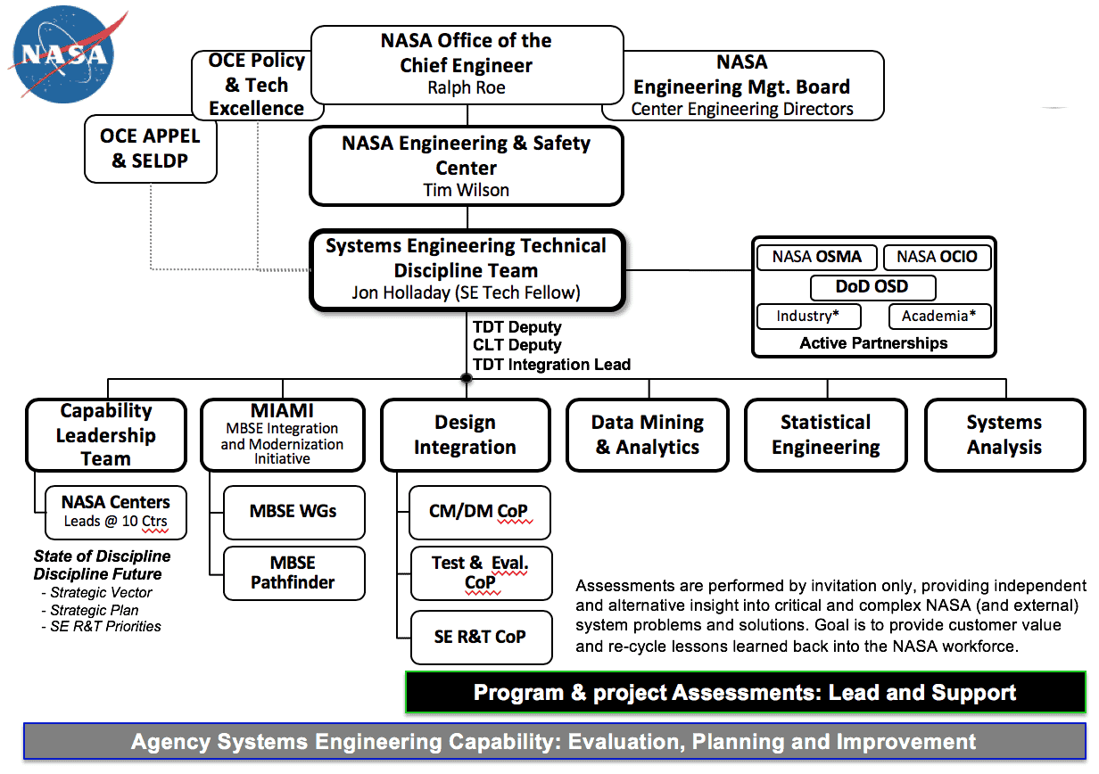
Figure 1: Organization of the NASA Systems Engineering Technical Discipline Team
Assessments
The mission of the NASA Engineering and Safety Center (NESC) is to perform value-added independent testing, analysis, and assessments of NASA’s high-risk projects to ensure safety and mission success. The NESC was established in 2003 to address a concern raised by Admiral Gehman, the Columbia Accident Investigation Board Chairman, that NASA lacked a strong program-independent resource to provide programs an alternate perspective on difficult technical issues. The NESC fills this need by bringing together technical experts from across NASA, industry, other government agencies, and academia and leveraging their expertise to solve problems. The NESC engages proactively to help NASA avoid future problems. Within that construct, numerous pathways exist to request this support, but most often it is via a program or project request to either validate a solution or implementation, provide an alternative view, or provide access to experts who may not readily be available within their organization. Anyone with an issue can also request with anonymity that the NESC become engaged in evaluating that technical challenge or concern.
Over the past year, three detailed assessments were performed by the SE TDT in support of NASA’s Human Space Flight (HSF) endeavors. Results were documented with findings, observations, and recommendations approved by the NESC Review Board (NRB) and then provided to the requesting stakeholder for their consideration. In all cases communication began with a submitted request, continued through the assessment process, and was provided on an as-needed basis after the results were released. A high-level summary of these three assessments includes improvement of interface definition and integration process across programs, simplification and improved verification closure responsibility allocation, and definitive approaches to deal with more agile approaches to SE. In addition to reporting, lessons learned during the assessment process are also captured in order to highlight and bring awareness to pitfalls which may not be commonplace or reflect the changing culture of NASA’s SE implementation.
This year, an additional three major assessment/support activities have been requested, and are now in work to support HSF Programs. One of them is providing support to, and evaluation of, the Exploration Gateway’s Early System Engineering & Integration (SE&I) approach. Gateway may well revolutionize the way NASA approaches the next phase of exploration by effectively mitigating risk of human rating an integrated assembly of commercial, NASA, and International human exploration systems. A fourth assessment is in work to address practitioner community best practices concerning technical risk and its relation to mass system growth. In addition to the assessments led by the SE TDT in the last year, over a dozen other assessments were supported via capabilities either owned or leveraged by the TDT in the areas of data mining, statistical engineering, and systems analysis.
All NASA SE assessments provide detail concerning the approach, evaluation, and analysis with clear, actionable recommendations leading to the safety and success of premier NASA Programs and Missions. Stakeholder feedback concerning implementation of TDT recommendations, although not required, helps validate the effectiveness of results both for the NESC and the stakeholder.
Capability Leadership Team
The second major responsibility of the NESC Technical Fellow (TF) and the TDT is stewardship of the Agency’s SE Capability via the SE Capability Leadership Team (CLT). The CLT is comprised of SE Leadership from all NASA Field Centers and the Jet Propulsion Laboratory (JPL). “State of the Discipline” evaluations are performed to understand current SE health, performance trends, and progress toward improvement goals and the future state. The latter is captured in the Agency’s SE Strategic Vector.
Every three years a detailed State of the Discipline analysis (also called a “deep dive”) is performed to fully understand the NASA’s SE deployment. This was most recently done in Fiscal Year (FY) 2016 and will be performed again in FY 2019. Discipline capabilities are generically defined at the Agency level as being comprised of three primary constituents; workforce, tools, and facilities. For the SE workforce, the characterization is further broken down into three components that characterize priorities needed to achieve mission success: leadership (people), technical savvy (product), and process (policy). An understanding of all three and how to most efficiently balance a response that mitigates risk and achieves mission success is a priority and key to achieving engineering elegance.
Two excellent discussions concerning SE were provided by NASA administrators Frosch (1969) and Griffin (2010). Mr. Frosch’s quotes from March 1969, just prior to NASA putting humans on the moon, is in my opinion one of the best focused calls to action papers on the priorities of Systems Engineering, and it still applies today. “As we are now behaving, we are using up our best people in filling out documentation for their superiors to read, and most of the time no one is running the store… We have lost sight of the fact that engineering is an art, not a technique; a technique is a tool… From time to time I am briefed on the results of a systems analysis or systems engineering job in a way that prompts me to ask the questions: “That’s fine, but is it a good system? Do you like it? Is it harmonious? Is it an elegant solution to a real problem?” In response, I often receive a blank stare and a facial expression that suggests I have just said something really obscene. We must bring the sense of art and excitement back into engineering. Talent, competence, and enthusiasm are qualities of people who can use tools; the lack of these characteristics usually results in people who cannot even be helped by techniques and tools. We can all do better.” Mr. Griffin some 30 years later, again addresses the issue: “The core purpose of the discipline of system engineering, and the primary responsibility of the system engineer, is the fielding of an elegant design. As discussed here, an elegant design is one which produces the intended result, is both robust and efficient, and generates a minimum of unintended consequences.”
In preparation for the FY2019 deep dive, and to further validate findings from previous efforts, including baseline of the SE Strategic Vector, an independent consultant interviewed the NASA SE workforce at large. Feedback from approximately 5% of the workforce was obtained. The interview population included an even split between early, middle, and senior level experienced SE practitioners, and also matched the distribution of support to the four mission directorates. A thorough and diverse set of metrics was obtained based on experience, mission, NASA Center size, programs and projects supported, etc., that continues to refine future efforts. Highlights of the interviews included high expectations for workforce in the three workforce priority characteristic areas as well as high scores on tech savvy, systems management, and workforce expertise/competence. Areas noted for improvement included the infusion of more advanced digital tools, such as Model Based Systems Engineering (MBSE), and improved awareness of the Agency level SE Community of Practice (COP).
Providing the appropriate SE skills, tools, and methods for the NASA workforce (within the guidelines of our policy and processes) is the leading priority for NASA Systems Engineering. NASA offers a world class recognized training program for Systems Engineers (and program/project managers), the Academy of Program/Project and Engineering Leadership (APPEL) as well as an Agency level Systems Engineering Leadership Development Program (SELDP). There are also more focused development programs provided at each NASA Center focused on building required SE skills based on their mission portfolios. All of these culminate with the opportunity to exercise those skills with varying degrees of hands-on experience, across all NASA systems and missions.
Model Based Systems Engineering (MBSE)
The NASA Systems Engineering community began evaluating the adoption of a digital approach or MBSE as early as 2011. The effort performed benchmarking of industry, evaluated standards, discussed infrastructure requirements, and interviewed NASA stakeholders. In FY 2016, at the unanimous direction of the SE CLT, the MBSE Pathfinder was developed to evaluate application of MBSE to some of the most challenging aspects of NASA spaceflight systems. The following year, the MBSE Pathfinder expanded to more rigorous implementation and coverage across multiple phases of the system engineering lifecycle. Two years of learning, alignment, and application resulted in over a dozen use cases that illustrate the benefits (and difficulties) of a digital framework for systems engineering. The MBSE Pathfinder informed the plans to move NASA towards an enterprise implementation of MBSE via the MBSE Infusion and Modernization Initiative (MIAMI).
MBSE Pathfinder
The first year, the MBSE Pathfinder was focused on “doing the impossible.” Rather than using a simple mission/system application to understand the ease, or difficulty, to do MBSE, four complex NASA missions were selected: Mars In-Situ Resource Utilization, an Exploration Class Lander, Advance Manufacturing of a Liquid Oxygen Methane Engine, and a Sounding Rocket mission flow. To maximize sociological aspects of implementation, teams were diverse and dispersed geographically across NASA Centers. The objective was to understand how difficult it was to utilize this new capability and capture lessons learned. In addition to achieving pathfinder objectives, results from each team went above and beyond the overarching goals, achieving many of the team’s program objectives for using MBSE to achieve effective Systems Engineering. The results of this MBSE Pathfinder are provided in an INCOSE paper, “NASA MBSE Pathfinder, Informing Next Steps in Engineering”.
The second year, the MBSE Pathfinder was focused on “winning the crowd.” The objective was to develop and expand MBSE proof of concept applications for better understanding and communicating value. The number of teams was doubled and complexity of the systems of interest increased. SE focus of some teams included re-use of models from year one, others focused on horizontal systems evaluation, and others vertical integration. At the end of year two, over a dozen use cases had been developed to demonstrate application, document lessons learned, and support movement toward implementation.
MBSE Infusion and Modernization Initiative
With a rich set of use cases and lesson learned, the MBSE Pathfinder was transitioned to the current MBSE Infusion and Modernization Initiative (MIAMI) project which encompasses the agency level effort to digitally transform NASA’s Systems Engineering discipline. Results based partnerships are in place within NASA to further accelerate and improve implementation. These include the Office of Safety and Mission Assurance to include Model Based Mission Assurance (MBMA) capabilities real-time across the life-cycle as well as the Office of the Chief Information Officer to consider both current and future plans for digital information architectures. External to NASA, working relationships exist with the Department of Defense’s Assistant Secretary of Defense for Research and Engineering as well as the Japan Aerospace Exploration Agency. Additional efforts are also in play to prioritize industry MBSE alignment and technological priorities to provide a seamless future, both tactically and strategically.
Conclusions
The NASA Art and Science of Systems Engineering paper provides the analogy of a systems engineer to that an orchestra maestro, or conductor. While NASA systems and missions definitely resemble the complexity of a symphony, I’d expand that context to include not only the conductor, but also the composer. After all, systems engineers are responsible for understanding the stakeholder needs and translating them to requirements and the resulting design to achieve those needs. Hence a technical understanding of the “instruments” or engineering disciplines, their capability/contribution, and how to engage them, is required as well as the process of documenting and delivering a pleasing and elegant “musical score” or design response. It’s about that which we do.
At a more fundamental level, being a NASA SE is also a lot like being the lead in a rock and roll band. It’s being part of a tightly connected team and understanding the members of your band, your team, and the audience. It’s the process of defining and delivering the music, the system to achieve the mission. It’s also revolutionary, integrating across cultural bounds (technically and sociologically) providing a shared knowledge of the world we live in and enabling growth beyond the immediate focus. Finally, when it’s done correctly, and the truly elegant solution, or objective, is obtained, it’s an emotional feeling that is motivating and addictively gratifying. It’s a lot like the feeling when AC/DC’s Thunderstruck intro fills the air at a University of Alabama football game (or any other large sporting event). It’s sometimes elusive, sometimes a lot harder than it looks, but always worth the effort in the end.
Epilogue
It’s an exciting time at NASA for Systems Engineering. In addition to the expanding complexity and breadth of missions, the new construct for SE Capability Leadership will help push the SE capability forward both within the Agency and on the national stage. With a framework in place to make SE “easier” for our workforce, we also look forward to the role NASA will have on making similar gains across all of industry. As Nick Saban, the coach of the University of Alabama (UA) football team states, “What we do is important, but how we do what we do becomes more and more important, and it’s for every guy (person) here in terms of how we do what we do. We’ve got to do it better.”
List of Acronyms Used in this Paper
Acronym Explanation
APPEL Academy of Program/Project and Engineering Leadership (APPEL)
CL Capability Leadership
CLT Capability Leadership Team
COP Community of Practice
FY Fiscal Year
HSF Human Space Flight
JAXA Japan Aerospace Exploration Agency
JPL Jet Propulsion Laboratory
OCE Office of Chief Engineer
OCIO Office of Chief Information Officer
OSMA Office of Safety and Mission Assurance
MIAMI Model Based Systems Engineering Infusion and Modernization Initiative
MBMA Model Based Mission Assurance
MBSE Model Based Systems Engineering
NASA National Aeronautics and Space Administration
NESC NASA Engineering and Safety Center
NRB NESC Review Board
R&T Research and Technology
SE Systems Engineering
SE&I Systems Engineering and Integration
SELDP Systems Engineering Leadership Development Program
TDT Technical Discipline Team
TF Technical Fellow
UA University of Alabama
U.S. United States of America
References
AC/DC, “T.N.T., It’s a Long Way to the Top”, Albert Productions, 1975.
[Author’s Note: the two AC/DC song references were used as an analogy of rock n roll bands in general; any similarly recognized band and/or song could be substituted. In many ways the elegance factor, IMHO, “fits” that of rock n roll. Perhaps another paper in the future will expound on this topic.]
Ryschkewitsch, M., et. al., “The Art and Science of Systems Engineering”, NASA Whitepaper, 2009. Available at https://www.nasa.gov/pdf/311199main_Art_and_Sci_of_SE_SHORT_1_20_09.pdf
NASA, Strategic Plan, 2018. Available at https://www.nasa.gov/sites/default/files/atoms/files/nasa_2018_strategic_plan.pdf
Roe, R., “10 Years and Counting, The NASA Engineering and Safety Center”, 2013. Available at https://www.nasa.gov/offices/oce/pmchallenge/sessions/2013_Session_2_abstract.html or
https://www.nasa.gov/sites/default/files/files/TechUp2013_PDFsp.pdf.
Frosch, R.A., “A Classic Look at Systems Engineering”, in Readings in Systems Engineering, NASA-SP-6102, 1993. [Author’s Note: From a speech given in in March 1969, keep in mind this was given four months prior to the USA winning the race to put a man on the moon.] http://www.eng.auburn.edu/~dbeale/ESMDCourse/Site%20Documents/Frosch%20on%20System%20Engineering.pdf
Griffin, M. D., “How Do We Fix System Engineering?”, 61st International Astronautical Congress, Prague, Czech Republic, 27 September – 1 October 2010. Available at https://www.aiaa.org/uploadedFiles/Events/How%20do%20we%20fix%20SE-Griffin.pdf
Weiland, K., and Jon Holladay, “NASA MBSE Pathfinder, Informing Next Steps in Systems Engineering”, INCOSE International Workshop, 2017.
https://onlinelibrary.wiley.com/doi/abs/10.1002/j.2334-5837.2017.00449.x. See also https://sma.nasa.gov/news/articles/newsitem/2018/06/27/osma-creates-mbma-program-to-improve-integration-of-assurance-considerations-in-mbse .
Altschuler, G.C., All shook up: how rock ‘n’ roll changed America (Oxford: Oxford University Press US, 2003). [Author’s Note: Numerous books and articles discuss rock “n” roll music’s impact on the culture of the globe, its ability to integrate and unify across cultural boundaries.]
AC/DC, “The Razor’s Edge, Thunderstruck”, Albert Productions/EMI, 1990.
“Training Days, Rolling with the Tide”, ESPN, Summer 2018. Available at https://www.youtube.com/watch?v=8nKDcIQoB10
[Author’s Note: A big part of Systems Engineering is integration, which includes leadership and motivation of the team toward a common goal. This series includes some interesting analogies on these areas as well as preparation.]
Blair, J.C., Robert S. Ryan, and Luke A. Schutzenhofer, “Engineering the System and Technical Integration” Lessons Learned in Engineering”, NASA/CR-2011-216472. June 2011. See https://ntrs.nasa.gov/search.jsp?R=20110012689. Available at https://ntrs.nasa.gov/archive/nasa/casi.ntrs.nasa.gov/20110012689.pdf
Blair, J.C., Robert S. Ryan, and Luke A. Schutzenhofer, “Elements of Engineering Excellence”, NASA/CR-2012-217471. November 2012. Available at https://ntrs.nasa.gov/archive/nasa/casi.ntrs.nasa.gov/20130000445.pdf
[Author’s Note: Bob Ryan and Jim Blair were two of my mentors as a young and enduring engineer. Mentorship is a significant contributor to the success of NASA engineers and these are two of the best. These are included simply for your reference on some facets and some more detailed thought on the NASA approach to engineering and the culture around it.]
About the Author

Mr. Holladay is currently assigned to the NASA Engineering and Safety Center as the Agency’s Technical Fellow for Systems Engineering. He has over a quarter century of experience in the human spaceflight arena, involving both spacecraft and launch vehicle development and operations, serving as both Chief Engineer and Engineering Project Manager. He holds a Bachelor’s and a Master’s degree in Mechanical Engineering from the University of Alabama and has completed the Legislative Studies Certificate Program at Georgetown University and the Senior Executive Fellows Program at the Harvard Kennedy School of Government. Previously, he served as the Project Lead/Chief Engineer in the SLS Advanced Development Office, where he focused on strategic analysis and planning for evolvability of NASA’s Space Launch System. Later, he was assigned to NASA Headquarters as a Senior Analyst for the Human Exploration and Operations Mission Directorate and the Agency’s Strategic Planning Office.
3. Additional Article
3.1 Three Ways to Ensure the Internet’s Future is Creative, Collaborative, and Fair
A multi-stakeholder approach and ‘day after tomorrow’ thinking are essential
by
Acting Head of Information and Entertainment System Initiative
Global Leadership Fellow World Economic Forum, Geneva
Last month the European Union’s governance body, the European Commission (EC), narrowly rejected controversial legislation intended to redefine copyright for the internet age, by only 40 votes. This new copyright directive was provisionally approved by the European Parliament’s Legal Affairs Committee in June, and the vote has forced the EC to debate and likely amend the directive before parliamentarians meet for a second plenary vote in September.
The directive of the European parliament and of the council on copyright has been a source of much global debate and controversy among various stakeholder groups, including civil society and both the tech and creative industries. Three specific clauses are of primary concern for these parties, with two particularly impacting digital content distributors: Articles 11, a proposed link tax on use of journalistic content, and 13, the imposition of a technical tool to identify copyright-protected content.
Have you read?
- The internet is at risk from rising sea levels
- The end of the 404? Why we need to repair the internet’s crumbling infrastructure
- What the global Internet’s stakeholders can learn from Europe’s new data law
The main arguments against Articles 11 and 13 surrounded the vagueness of certain key terms, the risks in providing flexibility in their interpretation, restriction of online freedoms, limits on fair use of copyrighted content, and creating an uncompetitive environment that favors large incumbent players or existing digital platform monopolies- an example is the Internet Society’s position on Article 13. On the other side of the debate, creative IP owners, artists, journalists and related associations had less to say about the language used in drafting the articles and more about how the internet has impacted their ability to be fairly compensated. Even after last month’s vote, little was offered in recommendations to redraft vague language.
However, both sides agree that (i) copyright policy for creative works is in need of a revamp due to digitization and changes in consumer behaviors, and (ii) artists and content owners should be fairly remunerated for certain uses of their works. The issue lies in how the EC’s directive was designed to support these two principles. The vagueness of the terms used, with too much flexibility in interpretation by nation states, and the potential of risk to online freedoms and in the enhancement of monopolistic power, are all details that risk doing the creative economy more harm than good. With the right approach to governance and policy formulation, however, they can be remedied.
Here are three things that the EC (and ultimately any policy-making body) should apply in conceiving a truly modern copyright directive for the creative economy:
1. “Day after tomorrow” thinking
The internet, as we commonly know it, is an aging platform. The Internet of Things is already here, which will take the sharing economy to the next level. We must collectively acknowledge that the sharing economy is the first new and established economic system since 19th-century capitalism and socialism – and this has fundamentally transformed our information ecosystem and our creative economy. Further, technologies such as hyper-realities (for example, augmented and virtual) and artificial intelligence will impact these at accelerated rates. A sign of outdated thinking within the EC’s new directive on copyright is its frequent use of the term “upload(ed)”, generally associated with owned content. At a time when research shows that “the preferences for streaming rather than downloading content continues to grow” across Europe, there is not one mention of “stream(ed)” or “streaming”, which is associated with a temporary use of content (not ownership).
Additionally, any directive and resulting policies must be innovative and robust enough to embody and address a “What if?” future, involving our emerging consumption patterns and behaviors. In its current form, by the time the EC’s copyright directive begins to be applied and enforced, content consumption and industry will have moved onto a different paradigm, creating a new set of challenges for copyright protection – this is the reality of the Fourth Industrial Revolution, and both the information and entertainment ecosystems are not being spared by its disruption. “Day after tomorrow” thinking focuses on longer-term impact considerations, and it helps organizations improve their chances of being ahead of the curve. Peter Hinssen’s future-thinking approach was designed for companies and organizations, but it is equally important for governance and policy making; in fact, this type of thinking can be applied to policy design in partnership with industry (see below), which would considerably change the current state of the EC’s copyright directive.
2. Systems thinking and agile governance
Systems thinking focuses on the dynamics between ecosystem stakeholders, trends, issues and other elements, which ultimately leads to a heightened understanding of the true impact variables have on the state of a system. Article 13 of the EU copyright directive is an example of something designed without using a systems approach. As noted by Frédéric Donck of the Internet Society, “civil society and academia, including the Electronic Frontier Foundation, European Digital Rights, Creative Commons and the Max Planck Institute for Innovation and Competition, have all raised concerns over the potential negative impact of Article 13 on freedom of expression, the rule of law, market competition and internet architecture as a whole”.
Anticipating the future, understanding trends and taking a systems approach to challenges such as copyright protection is not easy, nor is it a gameable science. As such, any decision-making body can get it wrong, so having the agility to react, shift course and adapt is becoming more and more an essential element to success – this is true of business and industry, and equally true for the public sector. Governments and policy-makers are doing society and the creative economy a disservice if they only focus on reactive policy implementation. An efficient reactive approach is important, in order to adjust existing policies, for example, but building adaptability into the DNA of any law or directive-making body is more important. How adaptable will the new EC Copyright Directive be to systemic change and developments in technology, consumption patterns and content format? Which stakeholders were involved in the design phase of the new directive? The World Economic Forum believes in the concept of agile governance, which not only considers emerging technologies, mitigates policy decay and makes policy-design faster and more responsive, but it also integrates a collaborative multi-stakeholder approach into the process.
3. A multi-stakeholder approach
Notice the reference to the creative “economy” and not simply “industries”. Industry is only one of many stakeholder groups impacted by any copyright directive and related policies. Besides the obvious member state governments, who are to apply an EU-wide directive, citizens who consume copyright-protected content will also be severely impacted by any new directive. This means that they, represented by civil society, should be at the table during the design of the directive. The EC should open the debate and reformulation of their copyright directive to a true multi-stakeholder approach.
Seizing the opportunity
The European Commission has a real occasion to adopt and pilot the use of these thinking and working models during the adjustment process for its new copyright directive. The World Economic Forum’s Shaping the Future of Information and Entertainment system initiative was created to act as a neutral multi-stakeholder platform to collaborate with central bodies such as the EC in addressing challenges facing the creative economy, including copyright and the economic existence of content creators. The EC should seize this opportunity and transform their copyright directive into a role-model success in governance for other governments and regulators around the world to follow.
About the Author
Claudio Cocorocchia has a Degree in Chemical Engineering, Queen’s University, Kingston, Canada; MBA, INSEAD. He began his career in management consulting. He moved to media with Sony Pictures Entertainment, working internationally across Sony’s Digital, Home Entertainment, and Television divisions for 6 years. Claudio was a member of the leadership team that founded Glu Mobile’s first international offices. In 2010, Claudio established and led Antaes Consulting’s Digital practice. At the end of 2014, he joined the World Economic Forum, where he currently is a Global Leadership Fellow and leads the System Initiative on Information and Entertainment.
Article
3.2 Integrating Program Management and Systems Engineering
by
Ralph R. Young
Editor, SyEN
Email: ryoung@ppi-int.com
This month we provide a summary of Chapter 15, Leading an Integration Change Program, in Integrating Program Management and Systems Engineering (IPMSE), a collaboration of the International Council on Systems Engineering (INCOSE), the Project Management Institute (PMI), and the Consortium for Engineering Program Excellence (CEPE) at the Massachusetts (USA) Institute of Technology (MIT). This is our sixteenth article in this series. Our objective in providing this series is to encourage subscribers to leverage the research base of this book that has provided new knowledge and valuable insights that will serve to strengthen the performance of complex programs. “The Book” is highly recommended as professional development for all systems engineers and is available to members of INCOSE at a discount.
This chapter looks closely into the change management aspects of the effort to integrate program management and systems engineering; considers the unique characteristics of the change initiative required to achieve an integrated environment; and provides key guidance for leading such an initiative within a variety of organizational settings. Chapter 13, Integration Means Change (reviewed in PPI SyEN 68, August 2018), provides an excellent starting point for the organizational change management thinking that must be present before, during, and after the execution of the integration program. Note that the use of the term “organization” includes the concept that programs are organizations as well, and can function as unique, identifiable entities within the enterprise. Accordingly, references to “organization” refer to the enterprise, as well as to the individual programs underway within the enterprise.
Whether the cause for concern has its roots in issues surfaced through interactions with employees, managers, senior managers, or executives, or perhaps from communication from external stakeholders, by the time business leaders begin seeking meaningful alternatives and solutions, the challenging issues that first inspired their investigative research have likely already taken a toll, leaving a significant and lasting impact on at least one part of the organization. It is this realization that causes the leader to act – responding with an increased sense of urgency. This realization that “something must be done” also places the leader in a difficult position. Suddenly becoming aware that “something within the organization must change,” implies the notion that subtle, or in some cases obvious, signals that indicated the need for organizational change had been missed or misinterpreted at some point along the way. When this occurs, it is important for the leader to pause and ponder the appropriate way forward. Leaders must carefully choose an approach for addressing change that will more likely foster success than failure and must stand firm in the face of considerable organizational resistance in their commitment to achieve it. Additionally, to be successful at bringing about meaningful and lasting change, leaders must look forward toward positive structural change for the organization, using facts and information about the existing conditions as a starting point while resisting the impulse to impose hastily conceived solutions, refraining from pushing for quick resolution, or looking backward into the current state seeking to identify the party or parties to who whom responsibility for the existing conditions can be assigned.
Finding and assigning blame for organizational difficulty will not contribute to the creation of an atmosphere for change within the organization. In fact, doing so has quite the opposite effect.
In response to the need for effective change, leaders will follow one of two similar but unique paths.
One path is based on a decision to contract with outside consultants and experts who will be brought into the organization to identify key improvement opportunities, then design and lead the necessary organizational change effort. The alternate route is the selection of change agents and champions from within the organization who will be empowered to create the environment for change and will endeavor to deliver on a commitment to make it happen. Selection of the latter path is based on the knowledge (or an assumption) that the necessary vision and talent is available within the organization.
It is important to note that the individuals chosen to lead organizational change are vitally important to the overall success of the effort. Leading an active organization through transformational change is a complex and challenging initiative. It’s likely that a cultural change program, such as an initiative to integrate program management and systems engineering, will be conducted within and across the organization over an extended period of time (years rather than months). The selection of change leaders for initiatives such as these, therefore, must be performed with studied and deliberate care. The leaders chosen for these initiatives must be perceived by stakeholders as inspirational, influential, persuasive, dynamic, and effective, or they face serious challenge leading the organization through difficult and extended transformational change. Many of the benefits of the change initiative may not be fully recognized or realized until after the conclusion of the program, compounding the challenge to sustain the initiative. Real evidence of the impact of the organizational change will be seen in the ongoing and sustained operation of the organization.
Chapter 15 proposes a five-part, success-enabling approach to implementing such a program. For the change management initiative to be successful, a leadership team needs to be formed, typically consisting of an executive sponsor (champion), program manager (charged with oversight and leadership of the change initiative), the Chief Systems Engineer (CSE) and systems engineering (SE) domain leaders (who bring deep technical experience and expertise and represent the organization’s broad SE environment), the Program Manager and program management domain leaders (who bring deep management experience and expertise and represent the organization’s broad program management environment), and leaders of the governance body (typically executives: partners and internal and external stakeholder leaders).
Critical parts of the change management program are the following:
- Planning.
The following components of the planning process are critical:
- Ensure senior leader support and commitment for the long term.
- Engage and gain commitment from across the organization.
- Develop a clear set of target outcomes, ways of performing and interacting, and establish performance targets and indicators at the start of the program.
- Meaningful measures and metrics for gauging progress against targeted objectives must be established at the start of the initiative and reviewed frequently during the life of the program.
- Design and implement processes for monitoring and governing the change initiative.
- Define and document clearly defined roles and responsibilities for both systems engineers and program managers.[2]
- Carefully select properly skilled individuals who will lead the change initiative.
- Systems and technology solutions that support the integration of program management and systems engineering within the organization must be put in place or modified to support the initiative.
To properly ground an important change initiative within an organization, those empowered to make it happen, including program management and systems engineering leaders, must do more than they believe they should to ensure that the organization fully understands the need for change.
- Observing and Interviewing.
- To be successful, those responsible for conducting the proposed integration program must be willing to invest the time necessary to fully assess the environment, and to establish, without bias or agenda, the true conditions and source of the trouble.[3]
- Documented observations will become particularly valuable when considering the metrics, measures, and indices that will be used to gauge the program’s progress and success.
- As the initial step of the program, observing the day-to-day operations and talking with (interviewing) program leaders, stakeholders, team members, and other staff will have an additional immediate benefit – engagement.
- The weakness of swiftly assessed problems and hastily implemented solutions is immediately sensed by the organization’s employees as well as the program team’s members and stakeholders.
Page 316 in The Book provides a list of questions that will help clarify the program management and systems engineering roles.
- Synthesizing, Sharing, and Mapping
Figure 15-2 in The Book presents the framework elements that must be present to achieve an integrated program management and systems engineering environment, where the recognized characteristics of the program are effective collaborative work, effective information sharing, and rapid and effective decision-making. The four input dimensions that influence effective integration are processes, practices, and tools; organizational environment; people competencies; and contextual factors, including program and team characteristics, organizational structure, and alignment with stakeholders.
When the observations, collected discussions, and interview information have been grouped summarized, and aligned to the framework, the next step is to share the information with the various leaders and staff who contributed to the discussion. This must be a delicately executed and carefully performed task, for it is the first step in generating trust for the change program and the people conducting it. The collected and summarized information ultimately will be shared broadly across the organization as significant component of the baselining activity. Those who volunteer information through discussion and interview must feel that the information accurately represents their views and perceptions.
The intent of the observations, discussions, and interviews is to develop a set of de-identified comments and perceptions that form a generalized “statement of condition” for the organization, and to build trust within the organization that honest and direct feedback can be shared without the threat of sanction or fear of retaliation. Sharing the collected information serves many purposes during program start-up:
- Honest feedback must be validated with those who originally contributed it before it is used for any other purpose.
- Creating trust is a cornerstone activity for the change program and its leaders.
- Sharing the information with the original contributors will engage them in the problem definition process and will set the tone for further dialog in the future. Clear, open, and honest communication among and across the program’s participants is essential for the ongoing success of the program.
After final review and acceptance by the original participants, the integration program’s leaders will map the grouped and summarized information to the various dimensions of the Integration Framework (recall that the Integration Framework emerged from the multiyear research activities that provided the basis for The Book, and that it is described in Chapter 6 and summarized in Figure 6-8 on page 114). Linking issues identified through observation, discussion, and interview to dimensions of the framework will ground future discussions in a formal structure that will facilitate communications and allow the organization to review, study, question, and “make sense of” the information as it is presented to them. This mapped information will make up the content for the initial communications and discussions held with organizational leaders, program sponsors, program participants, and stakeholders.
Having completed the above described aspects to enabling the success of the change program, organizational leaders are now ready to embark on a broad communications campaign within the organization. This step addresses the first two of five key change-enabling activities: Creating a sense of urgency; and Communicating the vision and alternatives.
As an organization prepares these first communications, the program’s sponsors and leaders must acknowledge that all of the work will not be accomplished in a single, sweeping action; and must design the communications as well as well as the program itself to address a set of prioritized program elements that will be addressed over time.
There are two essential components of this communication: a detailed explanation of what is anticipated if no action is taken, and a high-level vision of what the future can look like for the organization, with a call to action. Employees must perceive, or even better, believe, that there is a better future ahead, and must also feel that they can be a meaningful part of creating that future. Change champions, those who will be visible representatives of the organization’s commitment to support the program through to the end and who will lead the program through the entire duration of the effort, should be clearly identified and afforded as much authority to act as can reasonably be bestowed on the organization’s most senior leaders.
The change program’s leaders will begin the process of prioritizing the various sub-elements and program components that will be conducted (see the discussion on pages 324 – 327 for guidance concerning the prioritization process).
One of the most elusive aspects of change management programs, surprisingly, is not the achievement of target objectives and benefits, but rather sustaining changes and benefits once they have been achieved and delivered. Reviewing carefully some of these programs, even successful ones, reveals an interesting condition that is often overlooked: programs that initially succeed in bringing about intended changes are later found to be unsuccessful because the changes brought about by the program are not ingrained in the organization and the benefits that were achieved are not continuing to accrue.
To make changes “stick” within the organization and to ensure achieved benefits continue to deliver dividends beyond the end of the program, requires thoughtfully planned efforts to sustain them. For example, collaborative work, information sharing, and joint program management and systems engineering decision-making are examples of organizational culture that will be required to implement the necessary changes. Shortcutting the change management process leads to failed programs or the inability of the organization to sustain the benefits initially achieved. Each of the steps must be carefully understood, planned, performed, reviewed, reported, and repeated. A critical end-state is that the program manager and the chief systems engineer view themselves as partners who together share responsibility for the program’s success and outcome.
The above provides highlights of Chapter 15 in The Book, but you will want to read and digest the chapter to garner maximum insight! Organizations that successfully implement change over the long term repeat the processes outlined in this chapter on a cadence that focuses the entire organization on continuous improvement.
Following are some questions you might want to ponder:
- How can those feeling a need for change gain support from organizational leaders?
- What are the critical components of a change management program?
- What can be done in your organization to provide the base for a successful change management program?
- How can trust be generated, established, and sustained?
- How can we best ensure that employees feel they are a meaningful part of creating a better future?
References
Conforto, E. C., M. Rossi, Eric Rebentisch, J. Oehmen, and M. Pacenza. Survey Report: Improving Integration of Program Management and Systems Engineering. Presented at the 23rd INCOSE Annual International Symposium, Philadelphia, Pennsylvania USA, June 2013. Available at https://www.pmi.org/learning/library?q=Survey+Report%3A+Improving+Integration+of+Program+Management+and+Systems+Engineering
Erskine, P. ITIL and Organizational Change. Ely, England: IT Governance Publishing, 2013.
Knotter, John P. Leading Change. Cambridge, MA: Harvard Business Review Press, 2012.
Project Management Institute (PMI). Governance of Portfolios, Programs, and Projects: A Practice Guide. Newtown Square, PA, 2016.
Sirkin, H. L., P. Keenan, and A. Jackson. “The Hard Side of Change Management.” Harvard Business Review, October 2005. Available at https://hbr.org/archive-toc/BR0510.
4. Systems Engineering News
4.1 Asynchronous/Concurrent Agile Systems Engineering Life Cycle Model Framework Released by INCOSE
An INCOSE project team, led by Rick Dove, met with groups from different domains around the globe and found a diversity of meanings and applications concerning agile systems engineering. The effort led to the emergence of an agile systems engineering life cycle model (ASELCM) framework. Dove emphasizes that the value proposition for agile is risk and opportunity management; sustainability of innovation, processes and products that are at risk. This is in contrast to a more common belief that agile systems engineering is simply faster systems development at a lower cost.
The work and the ASELCM framework are described in an article written by Dove in the June 2018 issue of INSIGHT, the INCOSE magazine dedicated to advancing the state of practice in systems engineering and to closing the gap with the state of the art.
The article, “Enabling and Practicing Systems Engineering Agility – Prelude”, by Rick Dove, is provided on pages 8 to 12 of Volume 21/Issue 2, available to members of INCOSE here and provides a rich set of references available for exploration
Abstract
Agile systems engineering must function effectively in an engineering environment that is capricious, uncertain, risky, variable, and evolving (CURVE). This article leads off with methods for determining and justifying response capability requirements in such environments. These methods answer the questions: why is agility needed, and what must agility address? Subsequently, this article shows a framework for an agile system engineering lifecycle model (ASELCM) that has emerged from an INCOSE project concerned principally with determining such a model by analyzing real-world cases of what works. Together, the first enables effective process design, the second provides guidance for effective process practice. Finally, the article presents a synopsis of accompanying articles supporting the theme of this INSIGHT issue, enabling and practicing systems engineering agility.
About the author
Rick Dove is an INCOSE fellow, and chairs the working groups for Agile Systems and Systems Engineering and for Systems Security Engineering. He is CEO of Paradigm Shift International and an adjunct professor at Stevens Institute of Technology, teaching graduate courses in basic and advanced agile systems, systems engineering architecture and ConOps. He leads the current INCOSE project concerning discovering agile systems engineering lifecycle model fundamentals.
4.2 Space and Naval Warfare Systems Center (SSC) Atlantic USA Pilot Program Promotes Increased Systems Engineering Discipline
Space and Naval Warfare Systems Center (SSC) Atlantic recently implemented Model-Based Systems Engineering (MBSE) pilots to more efficiently build command and operations centers, and ultimately influence its long-term MBSE strategy.
As part of the pilots, the command and operations centers division regularly collaborates with mission engineers to develop mission-based analysis and engineering products through a holistic, MBSE approach to understand and improve end-to-end mission requirements and capabilities.
“Mission engineers provide quantitative analysis upfront on how the operations center is going to be used, which enables us to provide technical solutions and technical capability that will better facilitate operations at a more rapid pace,” said Donovan Lusk, command and operations centers division head. “Future projects will use those models so you’re not starting from scratch every time.”
The command and operations centers division partnered with mission engineers to pilot MBSE in a command center redesign for North American Aerospace Defense Command (NORAD) and U.S. Northern Command (NORTHCOM) at Peterson Air Force Base, Colorado, specifically focusing on adjacencies.
Mission engineers assessed the NORAD/NORTHCOM command center’s mission, processes, workflows and current operations to build essential models and model data to determine how best to align the user community to facilitate collaboration and operational dialog within the command center. Engineers used that data to create model diagrams representing structure and behavior that show how information is exchanged, which will inform the layout and design of the command center.
“Understanding the mission of the end-user is a crucial piece of building models and implementing MBSE,” said Leah Tuten, systems engineer and architect. “Stay engaged with your customer. Stay engaged with your stakeholders. They are the experts on what they do and we are the experts on systems engineering and designing command centers. Show them frequently what you have modeled, and make sure your model is your single source of truth.”
Historically, mission-level modeling and system and infrastructure-level modeling have been largely separated and unrelated. With MBSE, the mission model feeds into the overall system and infrastructure model that is used in command center environments.
“Model-Based Systems Engineering involves synchronizing those two different modeling worlds where the people who are making the technical decisions have a much keener knowledge of how those systems are going to be used by the operators and the missions they are supporting,” said Paul Walter, ashore systems engineering competency lead. “That’s the value of the command and operations centers pilot, seeing how we can better integrate those two different modeling domains.”
Other command and operations centers division MBSE pilots include modernizing a command center for U.S. European Command (EUCOM), gathering as-is technical architectures for U.S. 5th Fleet and U.S. 6th Fleet and modeling tasks from Naval Innovative Science and Engineering Maritime Operations Centers projects.
“MBSE is going to help us increase our systems engineering discipline by giving us a common language, a common capability and a common environment to engineer in,” said David Smoak, system of systems engineering lead. “That will improve how we deliver capabilities, how we share requirements, and how we actually do engineering.”
SSC Atlantic provides systems engineering and acquisition to deliver information warfare capabilities to the naval, joint and national warfighter through the acquisition, development, integration, production, test, deployment, and sustainment of interoperable command, control, communication, computers, intelligence, surveillance, reconnaissance, cyber and information technology capabilities.
4.3 INCOSE Introduces Purchasing Power Parity (PPP) Discounted Fees Effective January 2019
Effective 01 January 2019, Regular members may, but are not required to, avail themselves of the Purchasing Power Parity (PPP)[4] -based discounted fees outlined below.
PPP Band 1. 100% of the standard Individual member annual fee if the PPP of the country in which they reside is 50% or more of the PPP of the USA.
PPP Band 2[5]. 75% of the standard Individual member annual fee if the PPP of the country in which they reside is at least 25% and is less than 50% of the PPP of the USA.
PPP Band 3[6] (Transitional). 43% of the standard Individual member annual fee if the PPP of the country in which they reside is less than 25% of the PPP of the USA. This will be valid from 01 January 2019 until 31 December 2019.
PPP Band 3. 50% of the standard Individual member annual fee if the PPP of the country in which they reside is less than 25% of the PPP of the USA. This will be valid from 01 January 2020.
A full outline of INCOSE membership pricing dated 15 May 2018 is available here.
4.4 INCOSE 2018 Election Results
The Nominations & Election Committee announced the results of the 2018 election on the 2nd of October 2018. The following individuals will join the INCOSE Board of Directors on Saturday, 26 January 2018 when they are installed during the opening plenary of the 2018 International Workshop in Torrance, California.
Position (Term of Office)
- Secretary (2 years): Kayla Marshall
- Director for Marketing and Communication (3 years): Lisa Hoverman
- Director for Americas (3 years): Tony Williams
4.5 INCOSE Call for Fellows Nominations
The Fellows Selection Committee will be accepting nominations for new INCOSE Fellows submitted by INCOSE members until 1 December 2018.
INCOSE Fellows are individuals with significant verifiable contributions to the art and practice of Systems Engineering in industry, government or academia. This award recognizes practitioners from government and industry applying knowledge and contributing to the practice of systems engineering in designing and acquiring systems, researchers developing new knowledge and advancing theory, and teachers disseminating knowledge and developing the next generation of successful systems engineers.
Further details can be found here.
5. Featured Organizations
5.1 World Economic Forum
International Organization for Public-Private Cooperation

The World Economic Forum is a Swiss nonprofit foundation, based in Cologny, Geneva, Switzerland. Recognized in 2015 by the Swiss authorities as an “other international body” under Switzerland’s Host State Act 2007, its mission is cited as “committed to improving the state of the world by engaging business, political, academic, and other leaders of society to shape global, regional, and industry.
5.2 Infrastructure and Projects Authority, UK
The purpose of the Infrastructure and Projects Authority (IPA) in the UK is to continuously improve the way infrastructure and major projects are delivered, in order to support government priorities and improve people’s lives.
The IPA organization was formed on 1 January 2016 when it brought together Infrastructure UK (IUK) and the Major Projects Authority (MPA).
The IPA reports to both the Cabinet Office and HM Treasury. It is responsible for the overall project delivery system; the projects, people, and processes that together create the right environment for successful delivery.
Its responsibilities include:
- Supporting and de-risking the most complex and high-risk projects.
- Developing the skills and capability of the people who deliver projects.
- Overseeing the project life-cycle from policy, initiation, and financing to independent assurance.
6. News on Software Tools Supporting Systems Engineering
6.1 NPS-Developed Software Detects System Design Errors Early
A small group of Naval Postgraduate School (NPS) faculty has teamed up with NPS’ Center for Educational Design, Development, and Distribution (CED3) to develop a software-based tool which has the power to bridge the disparate worlds of computer science and systems engineering.
The Monterey Phoenix specification language and software, created by Computer Science department Associate Professor Mikhail Auguston, utilizes user input to generate process flowcharts which model a wide range of system behaviors, enabling users to visualize multiple outcomes before embarking on coding the system.
Visually seeing the work flow of an entire system this way significantly reduces potential human error in the design process before a single line of code is ever written, according to Auguston.
“The initial steps [of the design process] are mostly pencil and paper work,” he said. “Humans using pencil and paper have the ability to make mistakes, and those mistakes can become very expensive … This is where Monterey Phoenix comes in.”
The software tool does all of the heavy lifting of the ‘pencil and paper’ design process. The user simply describes relevant system actors – software, hardware, people, organization and/or environment – which are automatically rendered to create a graphic understanding of all possible scenarios.
“Most errors are not coding errors, but errors from the design and architecture of the code,” Auguston said. “There are steps that must be completed to move us from the problem to the final working code.”
The first step in designing a system is simply to understand what the problem is. Once this root problem – the ‘requirement’ – is discovered, it must then be broken up into sub-tasks and the workflow drawn out to see how each sub-task and component in the system will collaborate with one another.
Finally, in the design of the system, more detail is given to each sub-task in order to understand how they will act and interact with each other.
“Monterey Phoenix completes these steps for us,” Auguston said.
Kristin Giammarco, NPS Associate Professor for Systems Engineering, compared using the software tool to an orchardist pruning branches of an apple tree to yield the best quality and quantity of apples.
“The orchardist has to look into the future as they’re pruning branches and think which branches to keep and which branches to reject,” she said. “They’ll prune it so they’re encouraging desired behaviors and reducing or eliminating undesired behaviors of the tree.”
Monterey Phoenix basically visualizes that unpruned tree, enabling the human to step in and decide which branches to keep and which to reject.
“Monterey Phoenix unravels all the possible behaviors of the system before they become reality and manifest in the actual system,” Giammarco explained. “Once we have a visual of them in front of us, we can steer the design to avoid the unwanted behaviors.”
“This is a challenge in systems engineering today: it’s tough to predict because you can’t exclude what you don’t think of,” she added. “Monterey Phoenix solves this.”
Auguston and Giammarco believe Monterey Phoenix to be user-friendly enough to be accessible to people of varied skill levels, and hope that one day the program will be included in the regular toolkit of those – within the NPS community and beyond – looking to solve any behavior-related problem.
“It’s not a [replacement] to what people are currently doing,” Giammarco said. “This is an addition that verifies and validates the completeness of the work they’ve already done. They can take their data and run it through a Monterey Phoenix analysis to get results that help them improve their design and their tools.”
The team hopes that any user that is familiar and comfortable with programs like Microsoft Excel can easily and fearlessly use the tool to find failures in the behaviors of their own systems. One NPS student even wrote a simple ‘how-to’ manual for new users who want to learn how to use it for their own processes.
“It seems like a lot of people look at Monterey Phoenix and think it looks too complicated or too much like computer programming, and they get turned off by that,” said Megan Mosher, an NPS graduate. “I wanted to create the guide because I think Monterey Phoenix is an awesome tool with a lot of great capabilities, and hopefully the guide helps make it more accessible to people who otherwise might not use it.”
The tool has gained sponsorship within the Department of Defense from the Office of Naval Research, Naval Air Systems Command, the Systems Engineering Research Center, and several other organizations, and in 2017 was the subject of a research paper awarded the “Best Transition in Systems Engineering Research” at the 15th Annual Conference on Systems Engineering Research.
Monterey Phoenix continues to grow in recognition outside of NPS, and now the developers are hoping members of the NPS community, even beyond, will put the system to the test. For further information, visit http://firebird.nps.edu/ and the Monterey Phoenix wiki site (an official U. S. Navy website) for a trial of the latest version of the software.
Source: The Naval Postgraduate School Website
7. Systems Engineering Publications
7.1 Integrating SysML and Agent-Based Modeling for Rapid Architecture Evaluation
by
Apoorv Maheshwari; Ali K. Raz; Daniel A. DeLaurentis;
Andrew Murphy and Oluwatomi Kolawole
Published in the INCOSE Magazine, INSIGHT, June 2018
ABSTRACT
In the face of the changing operational requirements and demands for new capabilities, it often is necessary for systems architects to make substantial changes in a system’s architecture. However, traditional systems engineering processes, where architects finalized architecture during the initial concept development stages and engineers develop system simulations during later lifecycle phases, do not support a rapid architecture evolution. In this article, we propose a model-based systems engineering (MBSE) process to facilitate the rapid evaluation of changes in systems architecture and/or design artifacts for complex systems. This process specifies the minimum set of information that engineers need to include in systems architecture using SysML diagrams with traceability between the diagrams and the agent-based simulation (ABS) models of a complex system. By integrating SysML and ABS models early in the development lifecycle, teams can readily trace any future evolution of systems architecture represented by the SysML diagrams to changes in an ABS model and hence can rapidly evaluate the impact of architectural evolution. We demonstrate the application of the proposed process using a NASA-sponsored case study for developing ab initio architectures of the National Airspace System (NAS) where we achieved significant time savings in developing an ABS model of evolving NAS architecture based on SysML-ABS integration.
More Information
7.2 Information Technology Infrastructure Library
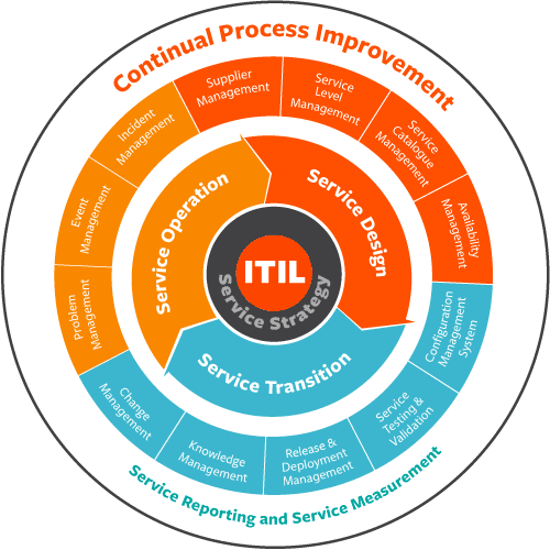
ITIL, formerly an acronym for Information Technology Infrastructure Library, is a set of practices for IT service management (ITSM) that focuses on aligning IT services with the needs of business. In its current form (known as ITIL 2011 edition), ITIL is published as a series of five core volumes, each of which covers a different ITSM lifecycle stage.
Source: Wikipedia
7.3 Continuous Testing for Continuous Delivery: What Does it Mean in Practice?
White Paper
by
Tom Pryce
When continuous testing is integrated in an end-to-end continuous delivery ecosystem, one has the ability to take ideas from design to operations faster, without compromising quality. One can iteratively and accurately capture desired user functionality, before delivery of your applications and software. Explore how you can align all of these components and adopt a continuous testing strategy from the user stories to test cases, test data, virtual services and deployment.
Available here.
7.4 Blue Ocean Shift: Beyond Competing
by
W. Chan Kim and Renee Mauborgne
W. Chan Kim and Renée Mauborgne are Professors of Strategy at INSEAD and Co-Directors of the INSEAD Blue Ocean Strategy Institute. They are the authors of the international bestseller Blue Ocean Strategy, which is recognized as one of the most iconic and impactful strategy books ever written. Blue Ocean Strategy is a bestseller across five continents, and is published in a record-breaking 44 languages. Kim and Mauborgne are ranked amongst the top 3 management gurus in the world in the Thinkers50 list and have received numerous awards from across the globe. They are Fellows of the World Economic Forum and the founders of the Blue Ocean Global Network. For more on these authors and their new book, BLUE OCEAN SHIFT, see www.blueoceanshift.com.
A review from Amazon:
The authors’ first book, Blue Ocean Strategy, was groundbreaking in its perspective on strategy, but the reader was left wondering whether it was in fact possible to implement it in real life, and the big question really is, how? The authors Kim and Mauborgne have thoroughly answered that question here, by explaining how an array of companies, non-profits, and even governments have successfully used blue ocean strategy in practice. What I like is that the examples in this book are entirely new and are covered in more detail than the first book.
I also like how they now provide a step-by-step guide, called the five-step process, to developing a blue ocean strategy that makes it so much easier to implement blue ocean strategy in reality. It takes away some of the uncertainty of the idea-creation process and makes it easy to try to develop your own blue ocean idea in your team or company.
If previously the concepts and tools of the first book were somewhat scattered and not entirely cohesive, in this book they lay out which tools are used in which step, and for what purpose.
7.5 Leading Change

by
John P. Kotter
From the Amazon website:
Millions worldwide have read and embraced John Kotter’s ideas on change management and leadership. From the ill-fated dot-com bubble to unprecedented M&A activity to scandal, greed, and ultimately, recession—we’ve learned that widespread and difficult change is no longer the exception. It’s the rule. Now with a new preface, this refreshed edition of the global bestseller Leading Change is more relevant than ever.
John Kotter’s now-legendary eight-step process for managing change with positive results has become the foundation for leaders and organizations across the globe. By outlining the process every organization must go through to achieve its goals, and by identifying where and how even top performers derail during the change process, Kotter provides a practical resource for leaders and managers charged with making change initiatives work. Leading Change is widely recognized as his seminal work and is an important precursor to his newer ideas on acceleration published in Harvard Business Review.
Needed more today than at any time in the past, this bestselling business book serves as both visionary guide and practical toolkit on how to approach the difficult yet crucial work of leading change in any type of organization. Reading this highly personal book is like spending a day with the world’s foremost expert on business leadership. You’re sure to walk away inspired—and armed with the tools you need to inspire others.
7.6 How Do We Fix Systems Engineering?
by
Michael D. Griffin
Paper presented at the 61st International Astronautical Congress, Prague
27 September – 1 October 2010
Editor’s Note: This is one of the references in the Featured Article provided above by Jon Holladay, NASA Systems Engineering Technical Discipline Team Lead and Technical Fellow. In this article, Michael Griffin suggests that a fundamental cause of the failure of complex systems is the lack of an elegant design – a design that produces the intended result, is both robust and efficient, and generates a minimum of unintended consequences. Griffin offers suggestions concerning that which we must do to meet the standard of elegance in a more systematic manner. Mr. Griffin is currently serving as Under Secretary of Defense for Research and Engineering, United States Department of Defense
The now half-century-old multidisciplinary, interdisciplinary discipline that we call “system engineering” is the classic half-empty, half-full glass; optimists and pessimists can look at the same thing and draw opposing conclusions. Optimistically, the maturing of system engineering into a recognized discipline from its roots in large aerospace and defense programs has been, and will remain, an enabling factor in the ability of societies to deal with the macroscale problems facing us in energy, environment, and other key areas. Pessimistically, system engineers have some explaining to do. How is it that we continue to encounter failure of important and complex systems where everything thought to be necessary in the way of process control was done, and yet despite these efforts the system failed? Each time this occurs, we as an engineering community vow to redouble our efforts to control the engineering process, and yet such events continue to occur. The answer cannot lie in continuing to do more of the same thing while expecting a different outcome. We need to rise above process, to examine the technical, cultural, and political mix that is “system engineering”, and to examine the education and training we are providing to those who would practice this discipline. This paper discusses that training from a new perspective, the perspective of design elegance, how we identify it, and how we can design with elegance as a value. Properly understood, the core purpose of the discipline of system engineering, and the primary responsibility of the system engineer, is the fielding of an elegant design. As discussed here, an elegant design is one which produces the intended result, is both robust and efficient, and generates a minimum of unintended consequences. Considerable work remains ahead to define and quantify these attributes in ways which are meaningful to the engineering community, and to develop methods and tools by which these goals may be attained.
Paper available here.
8. Education and Academia
8.1 Naval Postgraduate School
Monterey, California USA
The Naval Postgraduate School (NPS) is a graduate school operated by the United States Navy. Located in Monterey, California, it grants master’s degrees, engineer’s degrees and doctoral degrees. Established in 1909, the school also offers research fellowship opportunities at the postdoctoral level through the National Academies’ National Research Council research associateship program. The mission of the Department of Systems Engineering is to provide relevant, tailored, and unique advanced education and research programs in Systems Engineering in order to increase the combat effectiveness of US and Allied armed forces and to enhance the security of the United States. Systems engineering at the NPS focuses on the development of large and complex systems—how do all the parts work together in an integrated system, given the precise specification of the structure and behavior?
A master’s degree and a PhD in Systems Engineering are offered. The school is nationally ranked by US News[7] and recognized for the quality of our programs.
8.2 Cornell Engineering USA to offer Systems Ph.D. Program
Focusing on Logistics
A unique doctoral program in systems that will prepare students to tackle some of the world’s most complex logistical problems is now being offered by the graduate field of systems.
These social, business, and engineering problems often require individuals to produce solutions for different pieces of an operational challenge, but they also need a systems expert who can use a multidisciplinary approach to coordinate those efforts and ensure the different pieces fit together.
For instance, understanding the market for natural disaster insurance requires a systems thinker who can integrate models of natural hazards, building-specific structural vulnerability, consumer choice, insurance company competition and governmental action. Systems specialists also have the ability to face such challenges as organizing networks of Earth-observing satellites and predicting the transmission of disease-causing agents through the food supply chain.
Cornell’s systems doctoral program, approved by New York State in May 2016, accepted transfer students for the fall 2016 semester and is currently enrolling students. It will build on the success of the college’s 15-year-old master’s degree in systems.
The doctoral program is designed for students and professionals who have a strong technical background and are looking to take a leadership role within a research group or company, according to Patrick Reed, who teaches systems courses as a professor of civil and environmental engineering. The program will also provide distance-learning options for professionals wishing to maintain some level of employment while they pursue the degree.
“At a lot of other schools, this would be housed and strongly flavored by one department,” said Reed. “Whereas here at Cornell, the program is multi-departmental and you have everything from very classical engineering all the way through the social sciences that are already interacting with the systems program. Traditionally, that’s very difficult to do,” added Reed, who says Cornell Tech will eventually interact with the new doctoral program.
Daniel Selva, assistant professor of mechanical and aerospace engineering, also instructs systems courses and says Cornell’s strong academics in areas such as economics and the social sciences – aspects often overlooked in systems engineering – uniquely position the university to offer the degree. “We try to emphasize the human-centered aspect of designing complex systems. We do a lot of work with how you incorporate empathy into system design, for instance, and on improving the interaction between humans and computational design tools,” said Selva.
The curriculum for the program will be based on a number of required courses, complemented by two minors chosen according to the interests of each doctoral student. Students will also be required to participate in a case-based doctoral colloquium.
Graduates will be prepared to pursue careers as analysts, consultants and managers in the areas of aerospace, defense, energy, climate, water resources, information technology, healthcare, transportation, large-scale retailing, urban planning and many more.
“This is not learning existing techniques. These are people who are going to create the state of the art,” said Reed of the program’s students. “And so who do you turn to when appropriate techniques don’t exist for innovating complex systems? That’s a systems Ph.D.”
9. Some Systems Engineering-Relevant Websites
Best Graduate Industrial / Manufacturing / Systems Engineering Programs, U. S. News and World Report Education
A listing of the top graduate engineering schools for industrial / manufacturing / systems engineering. Each school’s score reflects its average rating on a scale from 1 (marginal) to 5 (outstanding), based on a survey of academics at peer institutions. The methodology used for ranking the schools is explained thoroughly on the site.
https://www.usnews.com/best-graduate-schools/top-engineering-schools/industrial-engineering-rankings
Review of Specialized Degree-Granting Graduate Programs of the U. S. Department of Defense in Science, Technology, Engineering, Mathematics, and Management (STEM-M)
This website gives access to an online-readable version of the report titled ‘Specialized Degree-Granting Graduate Programs of the Department of Defense in STEM and Management’ which focuses on the graduate science, technology, engineering, mathematics and management (STEM+M) education issues of the Air Force, Navy, and Marines. This report assesses the cost, benefits, and organizational placement of DoD institutions that grant degrees in STEM+M and evaluates alternative ways – for example, civilian institutions and distance learning – to ensure adequate numbers and high-quality education outcomes for DoD personnel.”- Publisher’s description
https://www.nap.edu/read/18752/chapter/4
Public Site of the ISO Working Group Mandated to Develop ISO/IEC 29110 Standards and Guides for Very Small Entities involved in the Development or Maintenance of Systems and/or Software
This website captures projects, case studies, surveys and other research carried out by the working group as well as other information on very small entities involved in the development of maintenance of systems and/or software. The general objectives of the working group are:
- To make the current software engineering standards more accessible to VSEs;
- To provide documentation requiring minimal tailoring and adaptation effort;
- To provide harmonized documentation integrating available standards:
- Process standards
- Work products and deliverables
- Assessment and quality
- Modeling and tools
- To align profiles, if desirable, with the notions of maturity levels presented in ISO/IEC 15504.
http://profs.etsmtl.ca/claporte/English/VSE/index.html
Capella Wiki Page
Capella is the Model-Driven Engineering (MDS) solution provided by Thales. This website is a Wiki Page intended for Capella end users and developers to collaborate, The page contains news, access to the Capella forum and free useful downloads for any current or prospective user.
https://wiki.polarsys.org/Capella\
Complex-Systems Design Methodology for Systems- Engineering Collaborative Environment
Online-readable and downloadable access to Chapter 2 of ‘Systems Engineering Practice and Theory’ written by Guido Ridolfi, Erwin Mooik and Sabrina Corpino. The chapter outlines methodologies designed for implementation in collaborative environments to support the engineering team and the decision-makers in the activity of exploring the design space of complex-system, typically long-running, models.
https://www.intechopen.com/books/systems-engineering-practice-and-theory/complex-systems-design-methodology-for-systems-engineering-collaborative-environment
10. Standards and Guides
10.1 Systems Engineering International Standards and Support Tools for Very Small Enterprises
by
Claude Y. Laporte, Ronald Houde, and Joseph Marvin
24th Annual International Council on Systems Engineering (INCOSE) International Symposium,
Las Vega, July 1st 2014.
Abstract
Very small entities (VSE) are very important to the world-wide economy. The products they develop are often integrated into products made by larger enterprises. To address their needs, a set of ISO/IEC 29110 systems engineering standards and guides, such as a management and engineering guide, has been developed using ISO/IEC/IEEE 15288. The INCOSE systems engineering handbook is used as the main reference for the development of a set of systems engineering deployment packages. A deployment package is a set of artefacts designed to facilitate the implementation of a standard or a set of practices in a very small entity. Two pilot projects using the new ISO/IEC 29110 are presented. A cost and benefits analysis from implementing ISO/IEC 29110 in an engineering firm is also presented as well as the future ISO/IEC 29110 management and engineering guide for start-ups and for projects requiring no more than six person-months of work. Finally, the certification scheme is discussed as well as future developments.
Conclusion and Future Work
Industry recognizes the contribution of VSEs in terms of the valuable products and services they offer. A large majority of organizations worldwide have fewer than 25 people. Most system and software engineering standards are not easily applied in VSEs, where they are generally found difficult to understand and implement.
Working Group 24 (WG24), mandated by ISO to develop standards and guides for VSEs, has developed a set of standards and guides to address the needs of VSEs developing a system or software. WG24 finalized in 2013 the development of the ISO/IEC 29110 systems engineering Basic profile. The INCOSE VSE WG produced a set of deployment packages to help implement the Basic profile. WG24 has started working on the Entry profile for systems engineering.
Once the ISO/IEC 29110 Intermediate and Advanced profiles for software are ready, work will start on the two corresponding systems engineering profiles for VSEs.
Since many VSEs around the world are developing components which are integrated in critical systems, WG24 and the INCOSE VSE WG will conduct an analysis to determine if a set of systems and software engineering standards for such VSEs should be developed.
Additional Information
The following Web site provides more information, as well as articles by WG24 members and
deployment packages for software and systems engineering: http://profs.logti.etsmtl.ca/claporte/English/VSE/index.html
ISO/IEC TR 29110-1:2011, Software Engineering – Lifecycle Profiles for Very
Small Entities (VSEs) – Part 1: Overview. Geneva, Switzerland: International Organization for
Standardization (ISO), 2011. Available at no cost from ISO at: http://standards.iso.org/ittf/PubliclyAvailableStandards/c051150_ISO_IEC_TR_29110-1_2011.zip
ISO/IEC 29110-2:2011, Software Engineering – Lifecycle Profiles for Very Small
Entities (VSEs) – Part 2: Framework and Taxonomy, Geneva, Switzerland: International
Organization for Standardization (ISO), 2011. Available from ISO at:
http://www.iso.org/iso/iso_catalogue/catalogue_tc/catalogue_detail.htm?csnumber=51151
ISO/IEC TR 29110-3:2011, Software Engineering – Lifecycle Profiles for Very
Small Entities (VSEs) – Part 3: Assessment Guide. Geneva, Switzerland: International
Organization for Standardization (ISO), 2011. Available at: https://www.iso.org/standard/51152.html
11. Some definitions to close on
11.1 Very Small Entity
A Very Small Entity (VSE) is an entity (enterprise, organization, department, or project) having up to 25 people. Worldwide, the percentage of micro and small enterprises is quite high. The table below shows that 92.2% of European enterprises have up to 9 employees, another 6.5% have between 10 to 49 employees. Micro enterprises account for 70% to 90% of enterprises in OECD (Organization for Economic Co-operation and Development) countries and about 57% in USA.
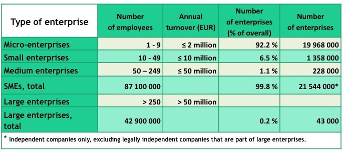
Figure 1: Size of Enterprises in Europe (Moll, R., Being prepared – A bird’s eye view of SMEs and risk management, ISO Focus +, February 2013)
Many Medium and Large enterprises, as illustrated below, need hardware and/or software components produced by VSEs. Finally, in large organizations, many projects have up to 25 people. Therefore, VSEs are found at all level of the pyramid below.
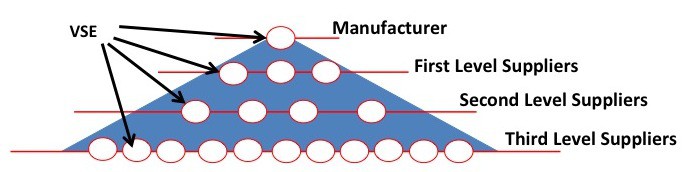
11.2 Systems Engineering Leading Indicators
What Are Systems Engineering Leading Indicators?
based on
SYSTEMS ENGINEERING LEADING INDICATORS GUIDE
Version 2.0
January 29, 2010
INCOSE
Note: This guide is available to INCOSE members at the INCOSE Store.
What are SE Leading Indicators?
A leading indicator is a measure for evaluating the effectiveness of a how a specific activity is applied on a project in a manner that provides information about impacts that are likely to affect the system performance objectives. A leading indicator may be an individual measure, or collection of measures and associated analysis that are predictive of future systems engineering performance before the system is fully realized. Systems engineering performance itself could be an indicator of future project execution and system performance. Leading indicators aid leadership in delivering value to customers and end users, while assisting in taking interventions and actions to avoid rework and wasted effort.
Who Developed the SE Leading Indicators?
An “SE Leading Indicators Action Team” was formed under the auspices of Lean Advancement Initiative (LAI) LAI, comprised of engineering measurement experts from industry, government and academia, involving a collaborative partnership with INCOSE. Mr. Garry Roedler of Lockheed Martin and Dr. Donna Rhodes of MIT co-led the effort. Leading SE and measurement experts from member companies, INCOSE, SSCI4, and PSM5 volunteered to serve on the team. The team held periodic meetings and used the ISO/IEC 15939 and PSM Information Model to define the indicators. The original version had thirteen SE leading indicators. Based on feedback from users, surveys, and workshops, a decision was made to revise the guide to add indicators and application information, as well as improve usability. For this revision, additional collaborative partners joined the team, including, NAVAIR, NDIA SED, and DoD SERC. Both versions have had significant support from a large number of industry partners identified in the contributors section of this guide. To date, eighteen SE leading indicators have been developed.
What Problem do SE Leading Indicators Address?
Leading indicators support the effective management of systems engineering by providing visibility into expected project performance and potential future states. Visibility into the future state of a project has not traditionally been part of a measurement process. Additionally, without the use of leading indicators, it is difficult for leadership to establish the likelihood of delivering a complex system within the project constraints such as scope, schedule, quality and budget.
Who are the Primary Users of the SE Leading Indicators?
The primary users are the project specific systems engineering leadership, project management, and IPT leadership who use the indicators to assess and make adjustments for assuring systems engineering effectiveness of the project. Selected indicators may also be used by the project customers, project partners, and project suppliers depending on phase of project and nature of the contractual relationship. Secondary users include executive and business area management, as well as process owners, for the purpose of predicting the overall effectiveness of systems engineering within and across a project, and for early detection of problems that require management attention.
How do SE Leading Indicators Differ from Conventional SE Measures?
A conventional measure provides insight into the issue areas of interest to management using historic and current status information. In contrast a leading indicator draws on trend information of conventional measures or significant correlation to provide predicative analysis. A leading indicator, for example, could use requirements growth to predict the future behavior of another process or sub-process. While the data on which both conventional measurement and leading indicators is similar, a key difference is that leading indicators address information needs that are predictive or forward looking. While the leading indicators appear similar to existing measures and often use the same base information, the difference lies in how the information is gathered, evaluated, interpreted, and used to forward-looking perspective.
How do SE Leading Indicators relate to Current Organizational SE Measurement Practices?
Most organizations have an organizational measurement plan and a set of measures. These leading indicators are meant to augment the existing set of measures. For optimal efficiency these should be implemented via the organization’s measurement infrastructure (typically based on CMMI® practices), thereby enabling mechanized data gathering, analysis, and evaluation. It should also be noted that leading indicators involve use of empirical data to set planned targets and thresholds. Where organizations lack this data, expert opinion may be used as a proxy to establish initial targets and thresholds until a good historical base of information can be collected, but should not be relied on as a long term solution for measurement projections. Rather, organizations must build the collection of the historical measurement data into its collection practices.
What is the Expected Impact?
These leading indicators have been specifically selected to provide insight into key systems engineering activities across the phases of a project.
What is an example of how SE Leading Indicators have contributed to effective systems engineering on a project?
A good example of the positive impact of using leading indicators was demonstrated within one of the pilots of the beta release guide. By monitoring the requirements validation and volatility trends, the pilot project team was able to more effectively predict readiness for the System Requirements Review (SRR) milestone. Initially the project had selected a calendar date to conduct the SRR, but in subsequent planning made the decision to have the SRR be event driven, resulting in a new date for the review wherein there could be a successful review outcome. That is, the review date was set based on an acceptable level of requirements validation and volatility in accordance with the leading indicators. Had the original calendar date been used, it is likely that the SRR would not have been successful and would have had to be repeated. See the example “Requirements Volatility” graphic.
Are the SE Leading Indicators Applicable to System of Systems Programs?
The leading indicators have primarily been derived from experience on traditional projects, however potential for use on System of Systems (SoS) projects has been given some consideration. First of all, some of the leading indicators are directly usable by a prime contractor as indicators for SoS level engineering activities. As SoS projects apply many of the same skills and perform many of the same activities as systems projects, the leading indicators do still apply. It is anticipated that in the SoS case, the interpretation of the leading indicators may involve some additional and/or unique considerations. For example how leading indicators, applied at the constituent systems level of a SoS, could be used effectively as a collected set of indicators and/or as aggregated indicators.
How will the SE Leading Indicators be Further Validated?
The further validation efforts will be monitored by the core team, in collaboration with the participating collaboration organizations. Based on results of project use, leading indicators will be adjusted as required. Additionally, recommendations will be developed regarding which leading indicators are most effective for particular types of projects.
What are the Plans for Improvement?
In support of the continuing validation and refinement activity, industry and academic research is ongoing and planned to analyze the effectiveness and adequacy of the measures in support of improved project performance. As lessons are learned in the continuing validation process, the core team will be providing briefings to and seeking input from selected government forums and systems engineering societies/associations. There are several activities planned for the future, including workshops on leading indicators involving cross discipline participation.
The ongoing maintenance of this guidance will be facilitated collaboratively by a leadership team from INCOSE, MIT, and PSM. This leadership team will meet on a regular basis, leveraging existing functions such as the INCOSE International Workshop, PSM Users Group Conference, and LAI Annual Conference in order to involve as many of the collaborative partners as possible. The ongoing work will include workshops with the contributors and interested parties to examine results of the indicators and opportunities for improvement. Consideration will be given to establishing a website to facilitate ongoing communication of contributors and users.
12. Conferences and Meetings
For more information on systems engineering related conferences and meetings, please proceed to our website.
13. PPI and CTI News
Preparation Underway for EnergyTech 2018
Over the last few weeks and months, PPI has been preparing for the various streams of participation to be fulfilled at the EnegryTech Conference in Cleveland, Ohio from 22-26 October 2018. The annual EnergyTech Conference & Expo is an organized event, supported by NASA and INCOSE, highlighting advancements in Energy, Smart-Grids and Microgrids, Aerospace, Critical Infrastructure, Security and Policy. In 2018, the EnergyTech collaboration efforts have been expanded to include professional societies such as InfraGard, IEEE, SAE, AIAA, PMI, and others, to join in advancing the technology and system integration of these complex domains, and managing the risk scenarios confronting civilizations. PPI will be exhibiting (please come and say hi to us at the booth!) and we are looking forward to networking with some of the leaders in the infrastructure and technology industry. In addition to exhibiting, PPI will be participating in the following ways:
- Tutorial: Fundamentals of Systems Engineering (Monday, 22 October 2018) hosted by Robert Halligan FIE Aust CPEng IntPE(Aus) with assistance from René King (BSc MechEng)
- Presentation: A Framework of Knowledge, Skills and Attitudes Conducive to High Performance Engineering (Tuesday, 23 October or Wednesday, 24 October- date to be determined) by Robert Halligan and René King
- Panel: Integrating Project Management and Systems Engineering (Thursday, 25 October) with Virginia Greiman, Randy Iliff, Mike Pafford and Robert Halligan
- Presentation: Practical Implementation of Project Management and Systems Engineering Integration, by Robert Halligan
PPI is looking forward to an exciting week of learning and sharing in Cleveland. We hope to see some of you there 😊
More Systems Engineering Training Options for you in 2019
A Range of Shorter Courses
PPI’s 5-day in-depth training courses on systems engineering and its sub-disciplines have, we are told by clients, improved client organizations and the lives of their staff through fundamental change in engineering practice. But not all organizations can make the investment of five days of the time of their teams and individuals.
PPI has introduced for 2019 a family of shorter, 3-day courses to match these circumstances. The following new courses for delivery in 2019 are now open for registration:
Systems Engineering Overview 3-Day
Requirements Analysis and Specification Writing Fundamentals 3-Day
Other new PPI in-depth courses for delivery in 2019 are:
Project Risk and Opportunity Management 3-Day
Medical Device Risk Management 3-Day .
You can view the full, worldwide schedule of PPI’s public courses for 2019 here. All public courses are also available for delivery at client premises worldwide. Other PPI training courses are only available for on-site delivery and are also listed. Monitor this page for additions.
PPI proud to be a sponsor of the annual lNCOSE South Africa
Conference
The 14th INCOSE SA Conference was held over Wednesday 3 through Friday 5 October 2018 at the CSIR International Convention Centre. The theme of this year’s conference is The Stone Age Did not End for a Lack of Stone—Human Innovation Did it. The conference was supported with around 150 delegates from across the country and was a terrific opportunity to meet with our INCOSE SA friends and colleague
Progress with INCOSE-PPI Collaboration on the
System Engineering Tools Database
Development of the Systems Engineering Tools Database (SETDB) is progressing smoothly thanks to participation from INCOSE members and PPI staff who meet weekly via web conferencing to discuss progress and allocate tasks. The core project team consists of project board members, John Nallon (INCOSE) and Robert Halligan (PPI), and project leaders Wesley Hewitt (INCOSE) and René King (PPI). Contributions from other INCOSE members during the meetings have been invaluable in gaining other perspectives. At the outset of the project, it was envisioned that a systems engineering approach to developing the SETDB would be adopted in order to ‘walk-the-talk’ for the systems engineering methodology that is championed by both organizations. So far this has gone according to plan and a set of use cases and the operational concept description (description of use) are in the mature stages of development. The capability-level system requirements specification is well underway and within the next few weeks, the requirements specification will be handed over to the INCOSE IT department so that the IT technical part of the solution solution may be developed. Process elements of the solution will be developed by the core team. All of the efforts of the team are directed towards presenting the prototype to INCOSE working groups for input and review in April 2019.
14. PPI and CTI Events
On-site systems engineering training is being delivered worldwide throughout the year. An overview of public courses is below. For a full public training course schedule, please visit https://www.ppi-int.com/course-schedule/
Systems Engineering 5-Day Courses
Upcoming locations include:
- Adelaide, Australia (P006-749)
19 Nov – 23 Nov 2018
- Eindhoven, the Netherlands (P006-750)
26 Nov – 30 Nov 2018
Requirements Analysis and Specification Writing 5-Day Courses
Upcoming locations include:
- Portland, OR, United States of American (P007-457)
29 Oct – 02 Nov 2018
- Stellenbosch, South Africa (P007-462)
03 Dec – 07 Dec 2018
Systems Engineering Management 5-Day Courses
Upcoming locations include:
- Ankara, Turkey (P1135-158)
- Nov – 09 Nov 2018
- London, United Kingdom (P1135-155)
10 Dec – 14 Dec 2018
Requirements, OCD and CONOPS in Military Capability Development 5-Day Courses
Upcoming locations include:
- Amsterdam, the Netherlands (P958-56)
03 Dec – 07 Dec 2018
Washington, D.C., United States of America (P958-59)
13 May – 17 May 2019
Architectural Design 5-Day Course
Upcoming locations include:
- LondonUnited KingdomP1768-17)
12 Nov – 16 Nov 2018
- Pretoria, South Africa (P1768-19)
06 May – 10 May 2019
CSEP Preparation 5-Day Courses (Presented by Certification Training International, a PPI company)
Upcoming locations include:
San Francisco, CA, United States of America (C002-81)
11 Feb – 15 Feb 2019
Bristol, United Kingdom (C002-91)
04 Mar – 08 Mar 2019
Other training courses available on-site only include:
- Project Risk and Opportunity Management 3-Day
- Managing Technical Projects 2-Day
- Integrated Product Teams 2-Day
- Software Engineering 5-Day.
15. Upcoming PPI Participation in Professional Conferences
PPI will be participating in the following upcoming events. We support the events that we are sponsoring and look forward to meeting old friends and making new friends at the events at which we will be exhibiting.
INCOSE Great Lakes Regional Conference
(Sponsoring)
Date: 17 – 20 October 2018
Location: Indianapolis, IN, USA
(Exhibiting)
Date: 22-26 October 2018
Location: Cleveland, OH, USA
New Zealand Defence, Industry & National Security Forum
(Exhibiting)
Date: 31 October – 1 November 2018
Location: Palmerston North, New Zealand
The INCOSE International Symposium 2019
(Exhibiting)
Date: July 2019
Location: Orlando, USA
The INCOSE International Symposium 2020
(Exhibiting)
Date:18-23 July 2020
Cape Town, South Africa
Kind regards from the PPI SyEN team:
Robert Halligan, Editor-in-Chief, email: rhalligan@ppi-int.com
Ralph Young, Editor, email: ryoung@ppi-int.com
René King, Managing Editor, email: rking@ppi-int.com
Project Performance International
2 Parkgate Drive, Ringwood, Vic 3134 Australia
Tel: +61 3 9876 7345
Fax: +61 3 9876 2664
Tel Brasil: +55 12 9 9780 3490
Tel UK: +44 20 3608 6754
Tel USA: +1 888 772 5174
Tel China: +86 188 5117 2867
Web: www.ppi-int.com
Email: contact@ppi-int.com
Copyright 2012-2018 Project Performance (Australia) Pty Ltd, trading as
Project Performance International.
Tell us what you think of PPI SyEN. Email us at syen@ppi-int.info.
- See: http://www.datacenterdynamics.com/content-tracks/design-build/reducing-risk-in-the-data-center/100396.fullarticle ↑
- See Conforto, Rossi, Rebentisch, Oehmen, and Pacenza, Survey Report: Improving Integration of Program Management and Systems Engineering (2013), for research that suggests that the definition of roles for the program manager and the chief systems engineer are often not formally defined. ↑
- See H. L. Sirkin, P. Keenan, and A. Jackson, “The Hard Side of Change Management” (Harvard Business Review, October 2005) for good suggestions. Available at https://hbr.org/archive-toc/BR0510 ↑
- PPP is a measure used by the World Bank to assess the relative sizes of the economies of countries ↑
- Countries of residence that qualify for this discount and which have current INCOSE membership are Argentina, Belarus, Brazil, Bulgaria, Chile, Costa Rica, Greece, Lithuania, Malaysia, Mauritius, Mexico, Poland, Romania, Russian Federation, Thailand and Turkey ↑
- Countries of residence that qualify for this discount and which have current INCOSE membership are China, Colombia, Ecuador, India, Indonesia, Morocco, Nigeria, Pakistan, Peru, Philippines, Rwanda, South Africa, Ukraine, Vietnam and Zimbabwe. ↑
- US News and World Report Ranking of Industrial, Manufacturing, and Systems Engineering Graduate Programs, 2014; and Review of Specialized Degree-Granting Graduate Programs of the Department of Defense in STEM and Management, National Research Council, 2014. ↑