Abstract
The Wedge Model™ is a derivative of the well-known Vee model. The Vee Model, possibly first defined by NASA in the 1960s, repeated by Barry Boehm in 1979 and Rook in 1986, has served well as a depiction of development of non- trivial systems through physical levels of solution description on the left-hand side of the Vee, and physical realization of system elements, together with implicitly their integration to create higher physical level system elements, on the right-hand side of the Vee. The Vee model has commonly shown verification of system elements that are on the right- hand side, against requirements for each element that are on the left. Whilst valuable, this depiction is a very limited representation of the reality of work products created in the development of non-trivial systems, and their verification and validation relationships. The Wedge Model extends the basic Vee model to incorporate verification and validation of requirements, design, system elements and system, within potentially a multiple-build development strategy. In doing so, the Wedge Model provides a framework for system-wide or project-wide planning and execution of verification and validation.
Description
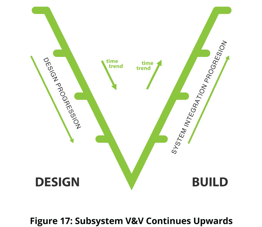
The Wedge Model is a derivative of the well-known Vee Model (Boehm, 1979) [1]. The Wedge Model shows the products of design on the left-hand side of the wedge, and the products of system integration on the right-hand side, with verification (is the work product correct with respect to the inputs used to create it – usually “meets requirements”?) and validation (does the work product correspond to the need for the work product?) superimposed. Colloquially, verification is – have we done the job right, and validation is – have we done the right job?
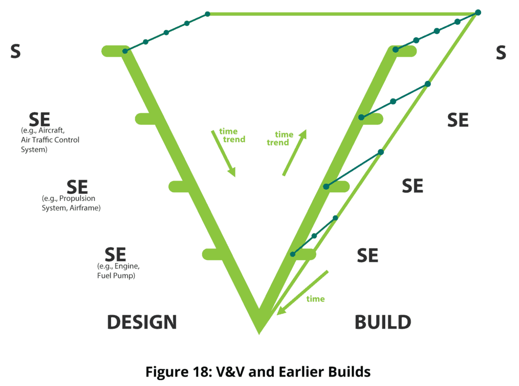
The Wedge Model shows multiple builds in a third dimension – a second time axis with time coming out of the screen or page towards the reader. Thus, the face of the Wedge represents the last build (version, release, etc.) in each case. All of the verification and validation concerns on the face are replicated back onto the earlier builds. Not all potential verifications and validations relating to earlier builds will be carried out; the aim is to perform the optimum amount of verification and validation such as to maximize the difference between the verification and validation risk reduction benefit versus the cost of achieving that benefit. It is an engineering management role to decide which of the work products will be subject to verification and validation, and to what degree.
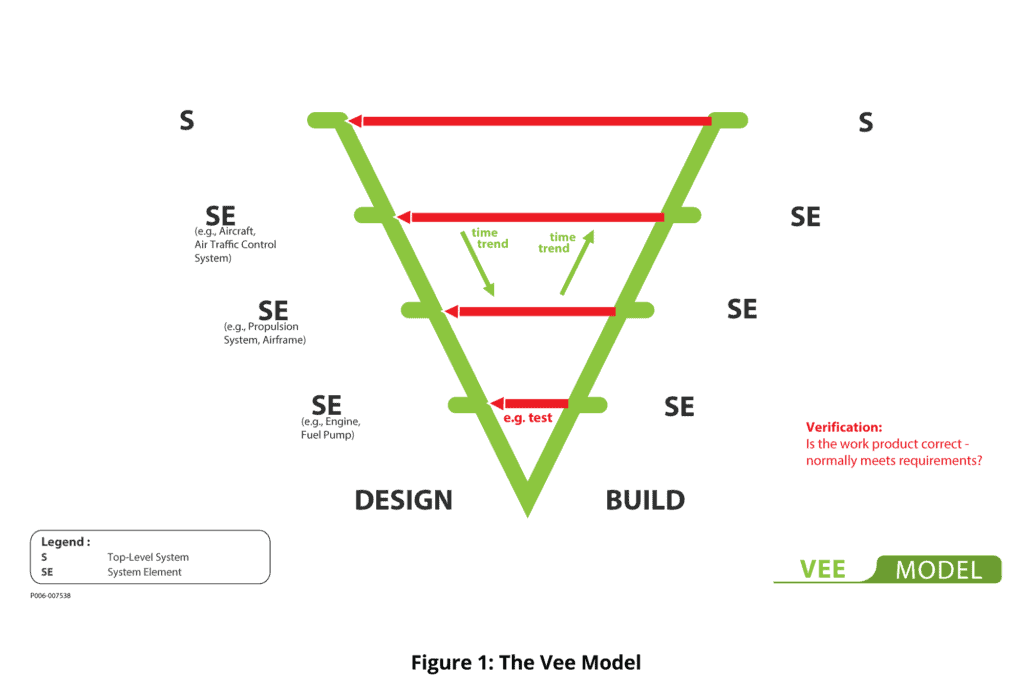
The original Vee model, shown at Figure 1, has been described from time to time as a development process model. It is not. The model shows the products of engineering work, and their problem-solution relationships, but is silent on how the work products were created. The original Vee model has also been described as a Waterfall model. It is not that either. In showing the end-product relationships between work products, the Vee model does not preclude, for any work product, a history of development of that work product ranging from agile per the Agile Manifesto at one extreme to waterfall (purely sequential) development at another.
The Wedge Model adds some of the story as to how the developer got there, but only insofar as intermediate design artifacts and corresponding intermediate builds are shown, along with verification and validation. Time trends are shown, but no strict time axes, even for incremental and evolutionary builds. These could be sequential or partly concurrent on each side of the Wedge. The timing dependencies are mostly finishing dependencies, not starting or doing dependencies (we have to have finished building the engine before we can finish building the propulsion system).
Attempts to add process to the Vee model have proliferated over the last thirty years, giving rise to an almost uncountable number of derivatives and mutations. Wings have been added at top left and top right in some derivatives to morph the model from a development model to a lifecycle model. Additionally, many different attempts have been made to show process between physical levels. In other versions of the Vee, physical levels have morphed to become levels of abstraction. These derivatives of the Vee model may well be useful. A downside is that each addition of a new type of information dilutes the focus on verification inherent in the original Vee.
The German V-Modell, a comprehensive instantiation of an alternative Vee model, incorporates processes, activities, disciplines, products, roles and decision gates [3].
Having established a context for the Wedge model, we now focus on the model itself. The Wedge Model retains the verification focus of the original Vee whilst expanding that verification focus. The Wedge Model also adds an equal focus on validation – of requirements, design, subsystems and system. This verification and validation focus of the Wedge Model has proven to be particularly useful in identifying candidate subjects of verification and validation, and representative methods of verification and validation in a large project context.
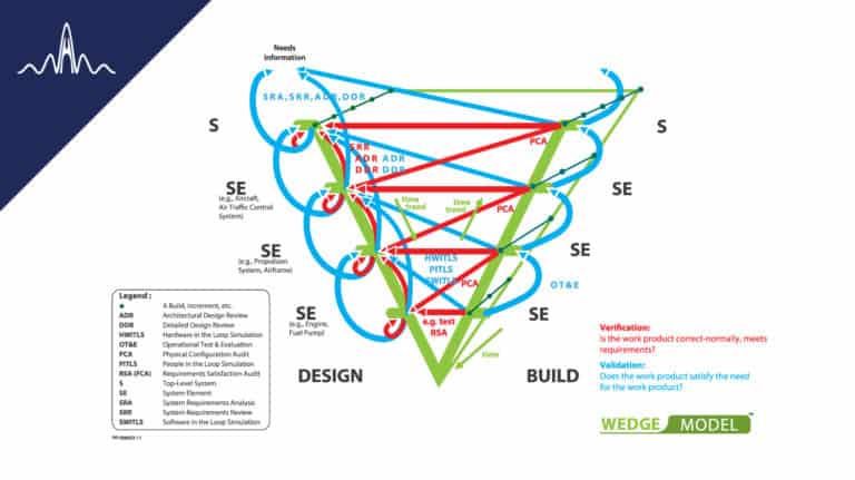
If the Wedge starts at the physical level of a capability system, a “Project System” invariably appears at Level 2 of the model, i.e. one level below the top system level. The Project System has system elements, and lower physical level system elements, and lower again, and again, down to, for example, individual test procedures and even individual emails. Each is subject to the same principles of verification and validation and the same relationships as for the technology elements of the capability solution. The full Wedge Model is shown in Figure 2.
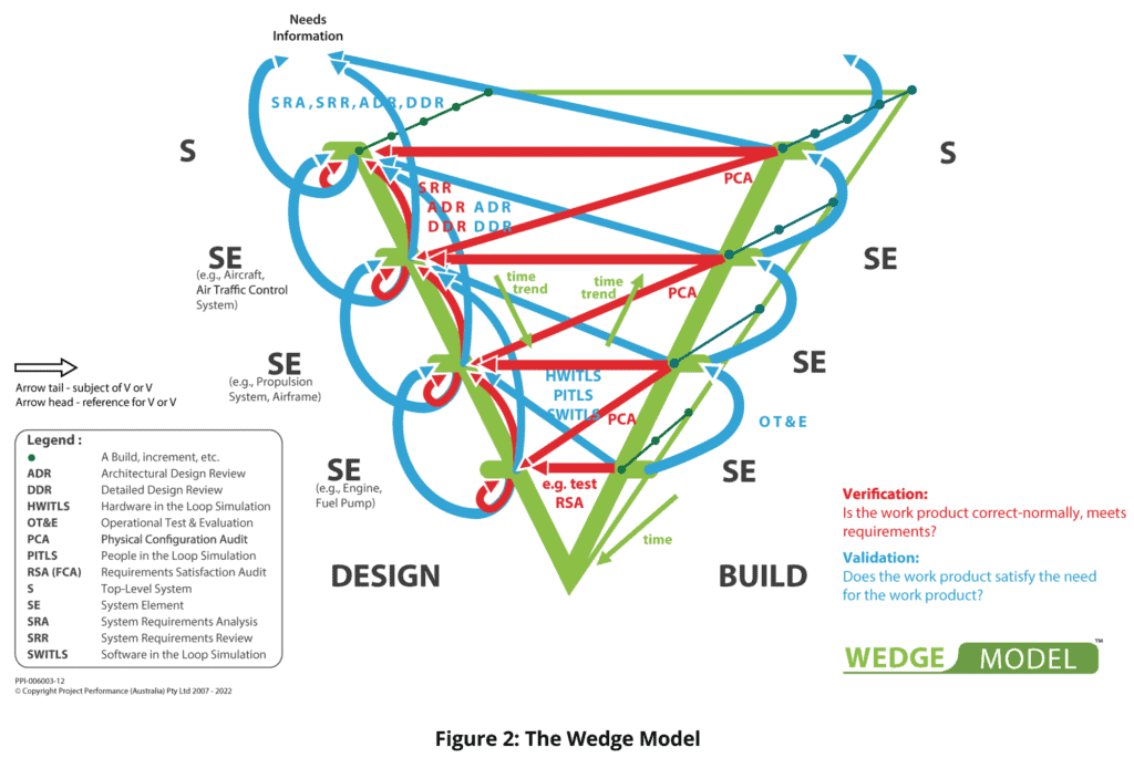
The model may appear to be a little complex, but is actually made up of a number of very simple parts, each reflecting a verification or validation engineering practice that is conducive to successful engineering. In the Wedge Model, the basic Vee model content is present, validation is added, verification beyond subsystem and system verification is added, and multiple builds are shown on an additional time axis. Notation-wise, the tail of an arrow originates from a subject of verification or validation, and the head of the arrow is pointing to the reference for that verification or validation. Verification and validation are represented in red and blue respectively, and are annotated with representative methods.
For validation, only the closest and typically most common physical level is shown as a reference. But validation can, in principle and practice, span multiple physical levels without limit.
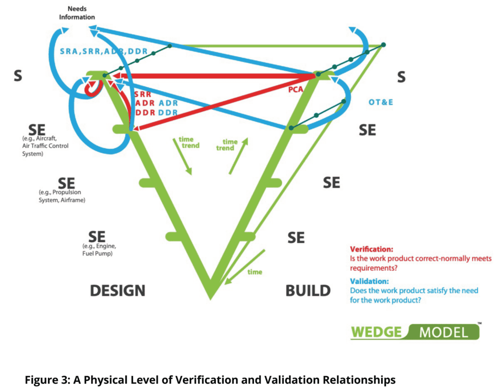
The basic set of relationships in the Wedge Model is shown at Figure 3 for a physical level of requirements specification at the top of the model, and the next physical level down of design/system elements below it. This pattern is repeated downwards through the physical levels, ending wherever a system element is non- developmental. Of course, the number of levels in each path from top to bottom is highly variable throughout the model, as will be the extent of verification and validation decided upon for each potential subject of verification and/or validation.
Often verification results at one physical level may be used as the evidence of compliance at the next physical level up, or as a part of that evidence. Such strategies are reflected in verification procedures or descriptions, and are not visible in the Wedge Model.
A description of the Wedge Model follows.
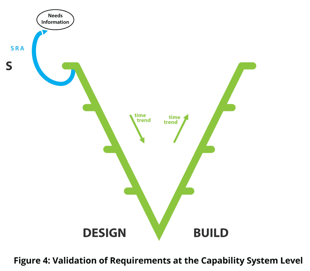
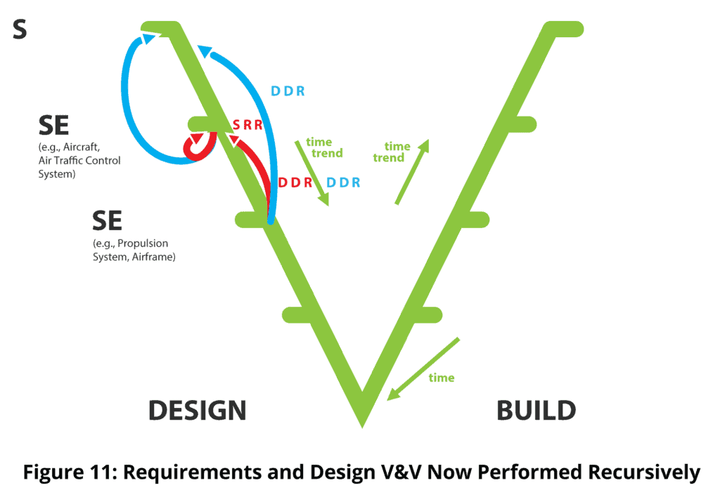
1. The model starts with the capture and validation of requirements at the top-level, in this case the enterprise or business or capability system level. That validation is carried out using mainly the methods of System Requirements Analysis (SRA), the validation activity show in blue at the top left.
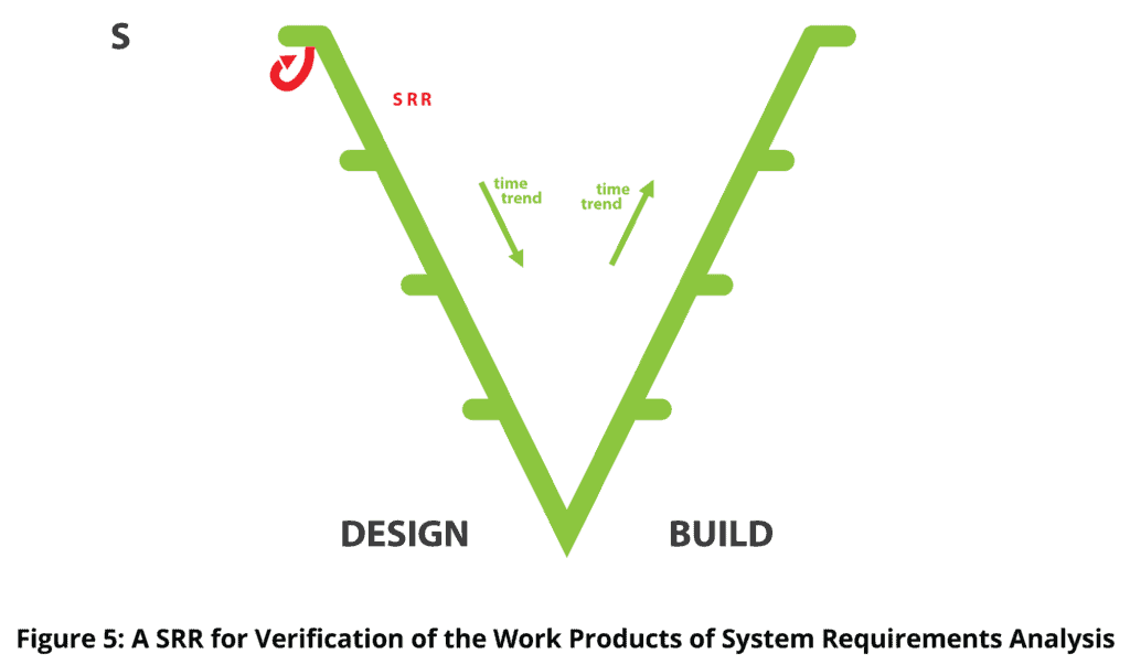
2. People make mistakes in performing system requirements analysis. Therefore, we want to verify the work products of the system requirements analysis. The most common and effective way of achieving this requirement work production verification is with a System Requirements Review (SRR), shown in red. Other methods of verification of requirements analysis work products may also be employed.
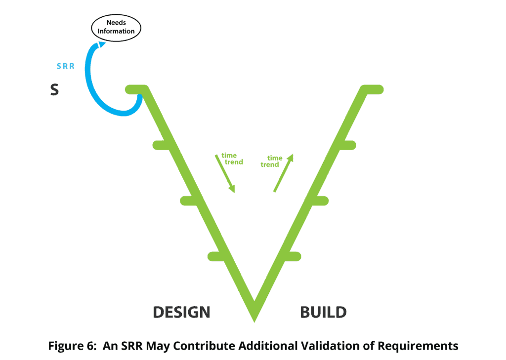
3. System Requirements Reviews (SRRs) also provide some additional requirements validation, although they are not very effective for this purpose. The SRR is also shown in blue at the top because of its requirements validation contribution.
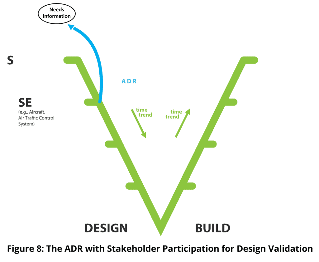
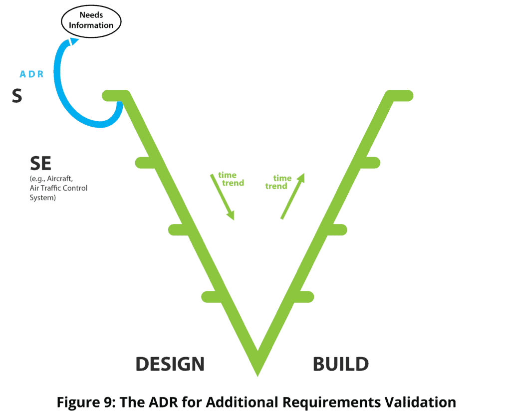
4. At some point in time, requirements are formally released and formally drive design. Architecture (i.e. conceptual design) is produced, and there is a desire to verify architecture before committing to the much greater effort of detailed detail. This purpose is most commonly served by an Architectural Design Review (ADR) shown in red. Architecture may also be verified by means additional to, or alternate to, design review. Here, the term architectural design is used with reference to a system of interest (Sol), and a physical level of design one physical level below the Sol.

5. It is all very well verifying architecture, but the reality that requirements validation and design verification can never be perfect is also well understood. So, the possibility always exists that a verified design to validated requirements is still inconsistent with meeting needs. We are therefore interested in design validation. A low cost, and the most common, way of achieving this design validation is to have stakeholders participate in the design review, thereby, through visibility to stakeholders of the design, identifying any failure to meet their needs. ADR is therefore also shown in blue for its validation contribution, but only if stakeholders participate.
6. If design is invalid for the usual reason that design is invalid, that is, because requirements are invalid or insufficiently complete, then we have achieved more requirements validation. Requirements validation is two steps removed from the primary purpose of a design review, but design reviews are purposefully used to achieve additional requirements validation by inviting stakeholder participation.
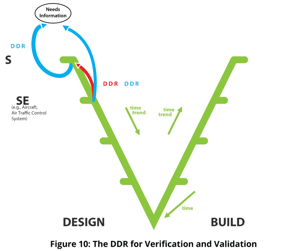
7. The corresponding comments apply to Detailed Design Review (DDR), for design verification, design validation and additional requirements validation, the last two only if stakeholders participate.
8. Eventually requirements on the sub-system, here for example the aircraft, are released, and it all starts again, and again, and again, until our development stops, here at, for example, the engine. Note that at level 2, where the aircraft appears in the example, another element will be the project system. If the Vee for that system is taken out and placed beside the aircraft Vee, we get the “Dual Vee” (Forsberg and Mooz, 1992), a view that is useful where the emphasis is the management of a project to create a product.
9. Eventually the engine comes into existence and there is a desire to verify that the engine meets the requirements for the engine, typically by test and other verification methods performed on the engine. Another verification method sometimes used is a Requirements Satisfaction Audit (RSA), also shown in red. The RSA is also sometimes referred to as a Functional Configuration Audit (FCA), a misleading and problematic name. The RSA activity goes through the whole body of evidence to answer the question “can we reasonably conclude that the engine meets the requirements for the engine?” The evidence examined includes test and other direct verification results, verification procedure used, test cases used (if applicable), calibration of test equipment, system configuration data, the disposition of failures, and any evidence of falsification of test results.
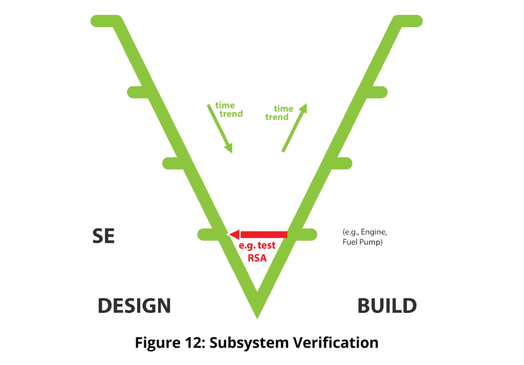
10. Having verified that the engine meets its requirements, we are now concerned with validating the engine – does the engine satisfy the need for the engine? This is most commonly achieved by operational test and evaluation, for example flight test. Equivalent methods in other sectors are clinical trials in the medical sector, and test marketing in consumer products.
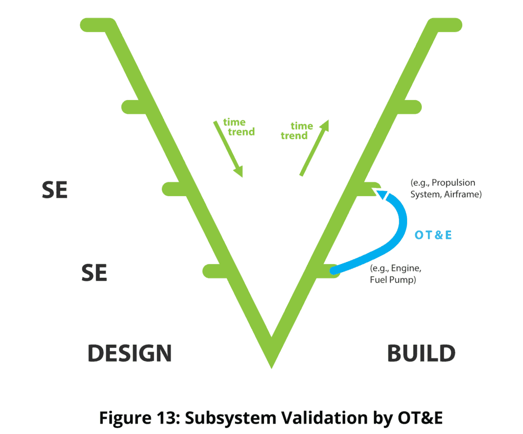
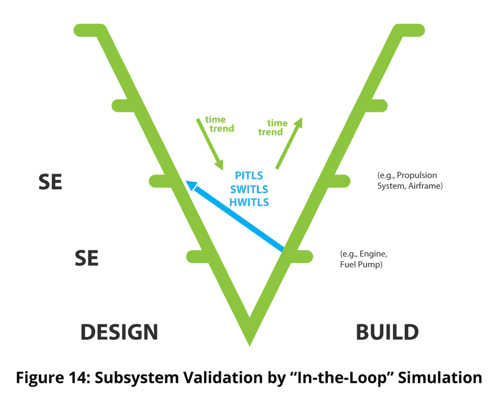
11. Flight testing an engine and finding that it crashes the aircraft is an undesirable approach. Another method of subsystem validation is Hardware-in-the-Loop Simulation, where the engine is exercised in a partly physical and partly simulated environment, and the results of the simulation analyzed to draw a conclusion on meeting need. For space subsystems and systems, “in-the-loop simulation” may be the only viable means of subsystem or system validation.
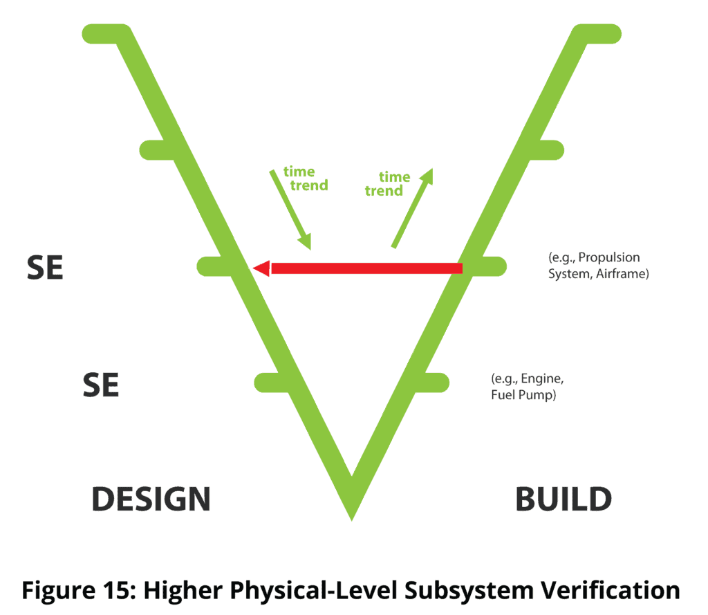
12. Eventually, through system integration, the propulsion subsystem comes into existence. It is verified by testing etc. as meeting its requirements. Aggregates of system elements are created in a typical system integration activity. Each aggregate is usually subject to integration testing. Integration testing can be regarded as a small “v” verification activity, performed by or for the system developers and lacking the independence normally sought for a formal verification activity. Some small “v” validation of system elements is also achieved within system integration.
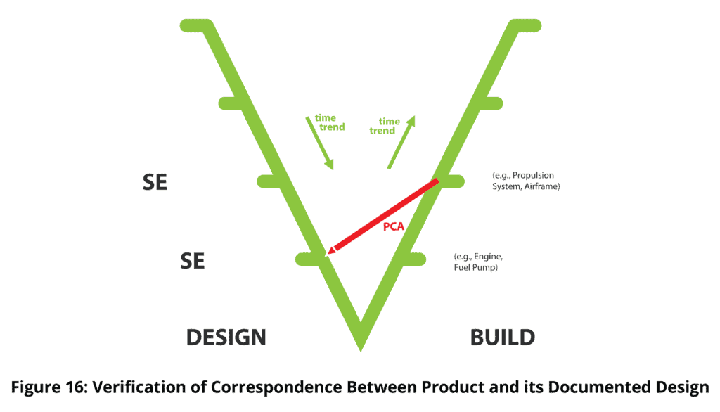
13. The red diagonal line pointing downwards indicates another verification activity. The activity addresses the concern “is the actual propulsion system built as described by its design description?” If the answer is no, we are compromised in maintaining the subsystem, replicating it, adapting it and fixing latent defects. A Physical Configuration Audit (PCA) may be used for this purpose. The PCA painstakingly compares the actual product against its design description, and identifies any inconsistencies.
14.Verification and validation generally continue up to the top-level system. At the level of the aircraft in the example, validation would typically be in the form of an operational trial, while at the top level for a military capability system, validation would typically be via a military exercise.
15. However, reality is that systems and subsystems will often be developed in multiple builds (releases, versions), sometimes for end use and sometimes for purely engineering reasons, or technical management reasons, for example, risk reduction. The Wedge Model shows multiple builds in the third dimension – a second time axis with the time coming out of the screen or page towards the reader. Thus, the face of the Wedge represents the last build (version, release, etc.). Each build has requirements, design and implementation. All of the verification and validation concerns on the face of the wedge are replicated back onto the earlier builds. Not all potential verifications and validations will be carried out on all of the products associated with all of the builds.
Conclusion
The Wedge Model provides a comprehensive representation of the end products and intermediate products within the development of larger, more complex systems, together with the superimposition of the subjects of verification and validation, the references for verification and validation, and representative methods of verification and validation. The representation accommodates both single build and multiple build development strategies for the end system itself and for each developmental system element.
References
[1] Boehm, B., “Guidelines for verifying and validating software requirements and design specifications”, in Proceedings of the European Conference on Applied Information Technology of the International Federation for Information Processing (Euro IFIP), Vol. 1, pp. 711-719, 1979.
[2] Rook,Paul,“ControllingSoftwareProjects”inSoftwareEngineeringJournal,Vol.1,No.1,pp.7-10,January1986,ISSN 0268-6961.
[3] The V-Modell XT, Version 2.3
Accessed 16 December, 2023
[4] Forsberg, K., and Mooz, H., “The relationship of systems engineering to the project cycle”. Engineering Management Journal, Vol. 4, No. 3, pp. 36-43, 1992.
")